Table of Contents
Advertisement
Advertisement
Table of Contents

Related Manuals for Observint CD600 Series


Summary of Contents for Observint CD600 Series
-
Page 1: User Manual
Infrared Turret Dome Camera User Manual Products: CD600 Series, CD601 Series, CD700 Series Cameras Please read this manual before installing and using this camera and always follow instructions for proper use. Save this manual for future reference. CD600-CD601-CD700_CM 11/14/13... - Page 2 CAUTION product and may cause a fire. © 2013 Observint Technologies. All rights reserved. 11000 N. Mopac Expressway, Building 300, Austin, TX 78759 1.800.335.9777 | Fax: 1.866.267.9777 For Sales/Support, please contact your supplier.
- Page 3 WARNINGS & CAUTIONS To prevent damage, do not drop the camera or subject it to strong shock or vibration. CAUTION If installed close to a TV, radio transmitter, magnet, electric motor transformer or audio speakers the magnetic field generated may interfere with or distort the image.
-
Page 4: Table Of Contents
SECTION 6 Troubleshooting . . . . . . . . . . . . . . . . . . . . . . . . . . . . . . . . . . . . . . . . . 19 www.observint.com... -
Page 5: Section 1 Features
SECTION 1: FEATURES Features SECTION 1 The CD600, CD601, and CD700 series cameras are weatherproof, vandal resistant turret dome cameras, ideal for outdoor or indoor locations where surveillance in low-light environments is required. These cameras include: Advanced image sensors for greater picture clarity •... -
Page 6: Camera Components
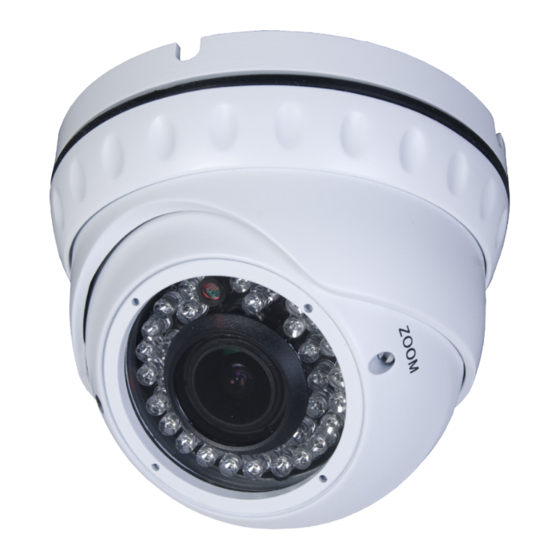
SECTION 1: FEATURES 1.1 Camera components Video 75 Ohm Drop Cable 12 V dc Base Bezel Camera Housing Camera Module Zoom Adjust (-VF Models) Camera Lens IR LEDs Camera assembly www.observint.com... -
Page 7: Camera Connections
SECTION 1: FEATURES 1.2 Camera connections Connect Connect Single camera with monitor Multiple camera system with DVR and monitor Infrared Turret Camera User Manual... -
Page 8: Section 2 Installation
To install the camera, you will need: Phillips #2 screwdriver • Small blade screwdriver (for adjusting VF model cameras) • Depending on how the camera is mounted, you may also need: Hammer • Drill with 3/32" and 3/16" drill bits • 3/4" hole saw • www.observint.com... -
Page 9: Installation Instructions
SECTION 2: INSTALLATION 2.3 Installation instructions Separate the base from the rest of the camera assembly by unscrewing the housing bezel. Bezel Remove the bezel 2. Determine where the camera will be mounted. Infrared Turret Camera User Manual... - Page 10 If the mounting surface is a soft material, such as a drywall, use a 3/16” bit to drill the mounting holes. Use a hammer to tap the wall inserts provided into each hole until they are flush with the surface. OR (continue on next page) www.observint.com...
- Page 11 SECTION 2: INSTALLATION 5. Drill mounting screw holes into the mounting surface. a. If the mounting surface is a soft material, such as a drywall, use a 3/16" bit to drill the mounting holes. Use a hammer to tap the wall inserts provided into each hole until they are flush with the surface.
- Page 12 SECTION 2: INSTALLATION Cable channel in base Drill a 3/4" hole through the mounting surface at the center of the base. 3/4" Drop cable routing hole Use a #2 Phillips screwdriver to mount the base with the provided screws. www.observint.com...
- Page 13 SECTION 2: INSTALLATION 8. With the camera in the camera housing, route the drop cable through the 3/4" hole until the camera housing is fitted onto the base. Place the housing bezel over the camera housing and screw it onto the base until the camera and camera housing are held in place.
- Page 14 SECTION 2: INSTALLATION Reassemble camera www.observint.com...
- Page 15 SECTION 2: INSTALLATION 12. Attach the BNC video/power cable to the camera cable as required. Notice that power connectors on the BNC video/power cable are different at each end! CAUTION Connect To DVR/monitor To DVR/Monitor and power and Power Cable attachment Infrared Turret Camera User Manual...
-
Page 16: Osd Setup (Cd700 Series Only)
Rock the joystick right (R) to highlight an option, UP or DOWN to identify the option, then press the joystick in to select it. Repeat this method to navigate the menu system and select options. www.observint.com... - Page 17 SECTION 2: INSTALLATION OSD MENU OPTIONS MANUAL LENS TYPE: DC / VIDEO AUTO MODE: CLOSE / AUTO/OPEN SPEED: 0-255 HIGH LUMINANCE MODE: SHUT+AUTO IRIS / AUTO IRIS BRIGHTNESS: 0-255 AUTO LOW LUMINANCE MODE: OFF / AGC SHUTTER/ BRIGHTNESS: ×0 .25, ×0 .5, ×0 .75, ×1 MODE: SHUT+AGC MAN- SHUTTER: 1/50, 1/120, 1/250, 1/500, 1/1000, 1/2000,...
- Page 18 DELAY CNT / DAY-NIGHT / NIGHT-DAY MODE: Y/C, OFF, Y, C CAMERA ID OFF/ON SYNC ENGLISH / CHINESE / JAPANESE / ESPANOL / PORTUGUESE / LANGUAGE PYCCKNN / FRANCAIS / DEUISCH CAMERA RESET / BACK / EXIT / SAVE ALL www.observint.com...
-
Page 19: Section 3 Aiming The Camera
SECTION 3: AIMING THE CAMERA Aiming the Camera SECTION 3 Connect the video cable from the camera to a test monitor or to the BNC input on the DVR. 2. Apply 12 Vdc power to the camera to power it on. 3. -
Page 20: Section 4 Cleaning
These may cause damage to the surface over time. Do not use benzene, thinner or other chemical products on the camera assembly; these may dissolve the paint and promote damage of the surfaces. Before using any chemical product, read the accompanying CAUTION instructions carefully. www.observint.com... -
Page 21: Section 5 Specifications
SECTION 5: SPECIFICATIONS Specifications SECTION 5 CD601WVF, Model CD600W, CD600B CD601W, CD601B CD601BVF Sensor 1/3" CMOS 1/3" SHARP CCD 1/3" SHARP CCD Effective Picture 728 (H) x 488 (V) 768 (H) x 494 (V) 768 (H) x 494 (V) Elements (H×V) Horizontal Resolution 600 TV Line 0.1 lux F1.2 /... - Page 22 (Ø131 x 93 (H) mm) Weight 15.9 oz (450 g) 28.2 oz (800 g) Storage Temperature -22 ~ 140 °F (-30 ~ 60 °C) RH 95 % max Operating Temperature 14 ~ 122 °F (-10 ~ 50 °C) RH 95 % max www.observint.com...
-
Page 23: Section 6 Troubleshooting
SECTION 6: TROUBLESHOOTING Troubleshooting SECTION 6 Before sending the camera for repair, please check below to make sure that the camera is installed correctly. If it still does not perform adequately, please consult your supplier. No picture on the monitor screen. a.
Need help?
Do you have a question about the CD600 Series and is the answer not in the manual?
Questions and answers