Table of Contents
Advertisement
Quick Links
Advertisement
Table of Contents

Subscribe to Our Youtube Channel
Related Manuals for Speco O2VLB2


Summary of Contents for Speco O2VLB2
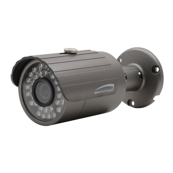
- Page 1 Owner’s Manual Full HD IP Bullet Camera O2VLB2 Version 1.0...
- Page 2 This owner’s manual is designed to be a reference tool for your system. Please read this manual carefully before operating the unit and retain it for future reference. Should you require any technical assistance, please contact Speco Technologies Technical Support.
- Page 3 Important Safeguards and Warnings . . . . E lectrical safety All installation and operation here should conform to local electrical safety codes. Use a certified/listed 12VDC Class 2 power supply only. Please note: Do not connect two power supplying sources to the device at the same time; it may result in device damage! The product must be grounded to reduce the risk of electric shock.
- Page 4 7. Accessories Before installation, please open the package and check that all the components are included. Contact your distributor immediately if something is broken/missing in your package. Accessory Name Amount Network Camera Unit Quick Start Guide Installation Accessories Bag...
-
Page 5: Table Of Contents
Table of Contents General Introduction ........................ 1 Overview ........................1 Specifications ......................1 1.2.1 Performance ......................1 Physical Specifications ......................2 Cable .......................... 2 Dimensions ......................... 3 Device Installation ........................5 IP Scanner ..........................7 Overview ........................7 Operation ........................7 Web Operation......................... -
Page 6: General Introduction
1 General Introduction 1.1 Overview This Speco device is a multi-codec (H.264, MJPEG) IP camera that integrates the traditional camera and network video technology. It enables real time transmission of synchronized video of full HD resolution. Built-in IR LEDs allows for a suitable image in low light environments. IP66 compliant housing allows for outdoor installations. -
Page 7: Physical Specifications
2 Physical Specifications 2.1 Cable Refer to the following figure for cable information. Figure 2-1 Cable Please refer to the following sheet for detailed information. No. Port Name Function Connection Note Network port Ethernet port Connect to standard Ethernet cable for power and data DC 12V Power input port DC jack Power port. -
Page 8: Dimensions
2.2 Dimensions Please refer to the following figure for dimension information. The unit is in mm. See Figure 2-3 to Figure 2-6. Figure 2-3 Figure 2-4... - Page 9 Figure 2-5 Figure 2-6...
-
Page 10: Device Installation
3 Device Installation Important Please make sure the installation surface can support a minimum of 3 times the weight of the camera. Figure 3-1 Device installation 1 Please see Figure 3-1 and Figure 3-2. Step 1 Put installation template on the designated surface where you will install the device (wall or ceiling). Step 2 Drill holes according to position of the holes on the installation template. -
Page 11: Step
Figure 3-2 Device installation 2 Step 6 Use Philip’s head screw (in accessories bag) to loosen adjusting screw. Step 7 Adjust the device to point to the desired angle. Step 8 Use Philip’s head screw to tighten the screws. -
Page 12: Ip Scanner
4 IP Scanner 4.1 Overview IP Scanner can search for the device on the local network. for the device on the local network. Please note that only devices that are on the same subnet can be discovered that only devices that are on the same subnet can be discovered. 4.2 Operation Open up IP Scanner. -
Page 13: Web Operation
5 Web Operation This device supports viewing and management via and management via a web browser on a PC. 5.1 Login and Main Interface Login and Main Interface Open the browser and input network camera address in the address bar and input network camera address in the address bar or double click the device in IP Scanner or double click the device in IP Scanner. -
Page 14: Faq
6 FAQ Water leakage has Removal of the front or rear cap may result in water leakage. occurred. The glass front cap has sustained heavy push or strike. The waterproof plug of the rear cap has loosened. IR video is poor. If there is not enough power, the IR LEDs may not function properly. -
Page 15: Appendix Toxic Or Hazardous Materials Or Elements
Appendix Toxic or Hazardous Materials or Elements Toxic or Hazardous Materials or Elements Component Name Cr VI PBDE Circuit Board ○ ○ ○ ○ ○ ○ Component Device Case ○ ○ ○ ○ ○ ○ Wire and Cable ○ ○ ○...
Need help?
Do you have a question about the O2VLB2 and is the answer not in the manual?
Questions and answers