Agilent Technologies E3633A User Manual
Dc power supplies
Hide thumbs
Also See for E3633A:
- Service manual (136 pages) ,
- Operating manual (175 pages) ,
- Service manual (112 pages)
Table of Contents
Advertisement
Quick Links
Advertisement
Table of Contents

Related Manuals for Agilent Technologies E3633A


Summary of Contents for Agilent Technologies E3633A
- Page 1 User’s Guide Part Number: E3634-90001 May 2013. For Safety information, Warranties, and Regulatory information, see the pages behind the Index. © Copyright Agilent Technologies, Inc. 1998–2013 All Rights Reserved. Agilent E3633A and E3634A DC Power Supplies Agilent Technologies...
- Page 2 The Agilent E3633A and Agilent E3634A are high performance 200 watt single- output dual range programmable DC power supplies with both GPIB and RS-232 interfaces. The combination of bench-top and system features in these power supplies provides versatile solutions for your design and test requirements.
-
Page 3: The Front Panel At A Glance
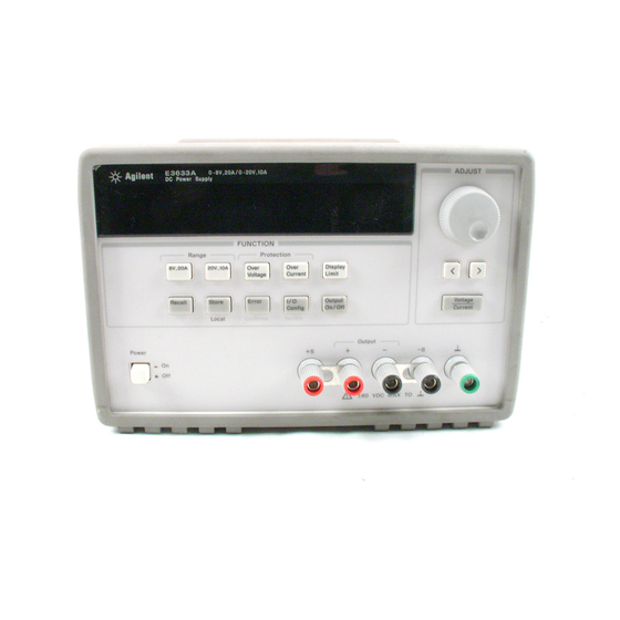
The Front Panel at a Glance 1 8V/20A range selection key (E3633A) 7 Store operating state/Local key 25V/7A range selection key (E3634A) 8 Error/Calibrate key 2 20V/10A range selection key (E3633A) 9 I/O Configuration/Secure key 50V/4A range selection key (E3634A) - Page 4 You can enable the ‘‘calibration mode’’ by holding down this key when you turn on the power supply. You can use it as the ‘‘Secure’’ or ‘‘Unsecure’’ key when the power supply is in the calibration mode. *For Agilent E3633A Model **For Agilent E3634A Model...
- Page 5 On/Off N o t e All front panel keys and controls can be disabled with remote interface commands. The Agilent E3633A and Agilent E3634A must be in "Local" mode for the front panel keys and controls to function.
-
Page 6: Display Annunciators
Power supply is addressed to listen or talk over a remote interface. Power supply is in remote interface mode. Shows the 8V/20A range is selected. (Agilent E3633A model) Shows the 20V/10A range is selected. (Agilent E3633A model) Shows the 25V/7A range is selected. (Agilent E3634A model) Shows the 50V/4A range is selected. - Page 7 The Rear Panel at a Glance 1 Power-line voltage setting 5 GPIB (IEEE-488) interface connector 2 Power-line fuse-holder assembly 6 RS-232 interface connector 3 AC inlet 7 Rear output terminals 4 Power-line module Use the front-panel key to: Config • Select the GPIB or RS-232 interface (see chapter 3). •...
- Page 8 Tutorial Chapter 7 describes basic operation of linear power supplies and gives specific details on the operation and use of the Agilent E3633A and Agilent E3634A power supplies. Specifications Chapter 8 lists the power supply’s specifications.
- Page 9 Declaration of Conformity (DoC) The Declaration of Conformity (DoC) for this instrument is available on the Agilent Web site. You can search the DoC by its product model or description at the Web address below. http://regulations.corporate.agilent.com/DoC/search.htm N o t e If you are unable to search for the respective DoC, please contact your local Agilent representative.
-
Page 10: Table Of Contents
Contents Chapter 1 General Information Safety Considerations- - - - - - - - - - - - - - - - - - - - - - - - - - - - - - - - 14 Safety and EMC Requirements - - - - - - - - - - - - - - - - - - - - - - - 14 Options and Accessories - - - - - - - - - - - - - - - - - - - - - - - - - - - - - - 15 Options - - - - - - - - - - - - - - - - - - - - - - - - - - - - - - - - - - - - - - - 15 Accessories - - - - - - - - - - - - - - - - - - - - - - - - - - - - - - - - - - - - 15... - Page 11 Contents Disabling the Output - - - - - - - - - - - - - - - - - - - - - - - - - - - - - - - - 52 Disabling the Output Using an External Relay - - - - - - - - - - - - - - - 53 Knob Locking- - - - - - - - - - - - - - - - - - - - - - - - - - - - - - - - - - - - - 53 System-Related Operations - - - - - - - - - - - - - - - - - - - - - - - - - - - - 54 Self-Test - - - - - - - - - - - - - - - - - - - - - - - - - - - - - - - - - - - - - - 54...
- Page 12 Chapter 7 Tutorial Overview of Agilent E3633A and Agilent E3634A Operation - - - 147 Output Characteristics - - - - - - - - - - - - - - - - - - - - - - - - - - - - - - 149...
- Page 13 Contents Output Isolation - - - - - - - - - - - - - - - - - - - - - - - - - - - - - - - - 153 Multiple Loads- - - - - - - - - - - - - - - - - - - - - - - - - - - - - - - - - 153 Remote Voltage Sensing - - - - - - - - - - - - - - - - - - - - - - - - - - 154 Load Consideration - - - - - - - - - - - - - - - - - - - - - - - - - - - - - 155 Extending the Voltage and Current Range - - - - - - - - - - - - - - - - - 157...
-
Page 14: Chapter 1 General Information
General Information... -
Page 15: General Information
General Information This is the User’s guide for your Agilent E3633A and E3634A DC power supplies. Unless otherwise stated, the information in this manual applies to both two models. This chapter provides a general description of your power supply. This chapter also... -
Page 16: Options And Accessories
Extra English manual set (local language manual files are included on the CD-ROM, Agilent part number 5964-8251) Accessories The accessories listed below may be ordered from your local Agilent Technologies Sales Office either with the power supply or separately. Agilent No. Description 10833A GPIB cable, 1 m (3.3 ft.) -
Page 17: Description
Chapter 1 General Information Description Description The Agilent E3633A and Agilent E3634A DC power supplies feature a combination of programming capabilities and linear power supply performance that makes them ideal for power systems applications. The power supply is programmable locally from the front panel or remotely over the GPIB and RS-232 interfaces. - Page 18 Chapter 1 General Information Description When operated over the remote interface, the power supply can be both a listener and a talker. Using an external controller, you can instruct the power supply to set the output and to send the status data back over the GPIB or RS-232.
- Page 19 Chapter 1 General Information Description W a r n i n g Outputs can be floated to maximum of ±240 Vdc provided that the metal shorting bars without insulation are either replaced with insulated conductors or they are removed from the terminals so there is no operator access to the output conductors without insulation.
-
Page 20: Installation
Keep the original packing materials in case the power supply has to be returned to Agilent Technologies in the future. If you return the power supply for service, attach a tag identifying the owner and model number. Also include a brief description of the problem. - Page 21 Option 1CM (P/N 5063-9243). Installation instructions and hardware are included with each rack-mounting kit. Any Agilent System II instrument of the same size can be rack-mounted beside the Agilent E3633A or E3634A DC power supply. Remove the front and rear bumpers before rack-mounting the power supply.
- Page 22 Chapter 1 General Information Installation To rack mount two instruments of the same depth side-by-side, order lock-link kit 5061-9694 and flange kit 5063-9214. To install two instruments in a sliding support shelf, order support shelf 5063-9256, and slide kit 1494-0015.
-
Page 23: Input Power Requirements
Chapter 1 General Information Input Power Requirements Input Power Requirements You can operate your power supply from a nominal 100 V, 115 V, or 230 V single phase ac power source at 47 to 63 Hz. An indication on the rear panel shows the nominal input voltage set for the power supply at the factory. - Page 24 Chapter 1 General Information Input Power Requirements 1 Remove the power cord. Remove the 2 Install the correct line fuse. Remove fuse-holder assembly with a flat-blade the power-line voltage selector from the screwdriver from the rear panel. power-line module. 100 or 115 Vac, 6.3 AT fuse 230 Vac, 3.15 AT fuse 4 Replace the power-line voltage selector 3 Rotate the power-line voltage selector...
- Page 25 Chapter 1 General Information Input Power Requirements...
-
Page 26: Chapter 2 Initial Operation
Initial Operation... -
Page 27: Initial Operation
Initial Operation There are three basic tests in this chapter. The automatic power-on test includes a self- test that checks the internal microprocessors and allows the user visually to check the display. The output check ensures that the power supply develops its rated outputs and properly responds to operation from the front panel. -
Page 28: Preliminary Checkout
The following steps help you verify that the power supply is ready for use. 1 Check the list of supplied items. Verify that you have received the following items with your power supply. If anything is missing, contact your nearest Agilent Technologies Sales Office. One power cord for your location. This User’s Guide. -
Page 29: Power-On Checkout
N o t e If the power supply detects an error during power-on self-test, the ERROR annunciator will turn on. See "Error Messages" for more information starting on page 123 in chapter 5 *For Agilent E3633A Model **For Agilent E3634A Model... -
Page 30: Output Checkout
Adjust the knob until the voltmeter indicates 0 volts and then adjust the knob until the voltmeter indicates ‘‘ volts’’* or ‘‘ volts’’** 25.0 You can use the resolution selection keys to move the blinking digit to the right or left when setting the voltage. *For Agilent E3633A Model **For Agilent E3634A Model... -
Page 31: Current Output Checkout
Turn the knob clockwise or counter clockwise when the display is in the meter mode (the annunciator is off). Check that the ammeter responds to knob control and Limit the voltmeter indicates nearly zero (the voltmeter will show the voltage drop caused by the test lead). *For Agilent E3633A Model **For Agilent E3634A Model... - Page 32 N o t e If an error has been detected during the output checkout procedures, the ERROR annunciator will turn on. See "Error Messages" for more information starting on page 123 in chapter 5 *For Agilent E3633A Model **For Agilent E3634A Model...
- Page 33 Chapter 2 Initial Operation Output Checkout...
- Page 34 Front-Panel Operation...
- Page 35 Front-Panel Operation So far you have learned how to install your power supply and perform initial operation. During the initial operation, you were briefly introduced to operating from the front panel as you learned how to check basic voltage and current functions. This chapter will describe in detail the use of these front-panel keys and show how they are used to accomplish power supply operation.
-
Page 36: Chapter 3 Front-Panel Operation Front-Panel Operation Overview
HP-IB interface, the annunciator will turn on. See “Display Annunciators’ on page v for more Adrs information. *For HP E3633A Model **For HP E3634A Model... -
Page 37: Constant Voltage Operation
Adjust the knob to the desired current limit. You can use the resolution selection keys to move the blinking digit to the right or left when setting current. Voltage Current 5 Adjust the knob for the desired output voltage. *For HP E3633A Model **For HP E3634A Model... - Page 38 CURRent {<current>|MIN|MAX} Set the voltage VOLTage {<voltage>|MIN|MAX} Enable the output OUTPut ON You can use the resolution selection keys to move the blinking digit to the right or left when setting voltage. *For HP E3633A Model **For HP E3634A Model...
-
Page 39: Constant Current Operation
Adjust the knob for the desired voltage limit. You can use the resolution selection keys to move the blinking digit to the right or left when setting the voltage. *For HP E3633A Model **For HP E3634A Model... - Page 40 VOLTage {<voltage>|MIN|MAX} Set the current CURRent {<current>|MIN|MAX} Enable the output OUTPut ON You can use the resolution selection keys to move the blinking digit to the right or left when setting the current. *For HP E3633A Model **For HP E3634A Model...
-
Page 41: Storing And Recalling Operating States
Chapter 3 Front-Panel Operation Storing and Recalling Operating States Storing and Recalling Operating States You can store up to three different operating states in non-volatile memory. This also enables you to recall the entire instrument configuration with just a few key presses from the front panel. - Page 42 Chapter 3 Front-Panel Operation Storing and Recalling Operating States Store 4 Save the operating state. The operating state is now stored. To recall the stored state, go to the following steps. DONE Recall 5 Turn on the recall mode. Memory location “1” will be displayed in the recall mode. RECALL 1 This message appears on the display for approximately 3 seconds.
-
Page 43: Programming Overvoltage Protection
Note that you cannot set the trip levels to lower than 1.0 volt. Over Voltage 4 Enable the OVP circuit. OVP ON Over You will see the above message after pressing key. Voltage *For HP E3633A Model **For HP E3634A Model... -
Page 44: Checking Ovp Operation
Chapter 3 Front-Panel Operation Programming Overvoltage Protection Over 5 Exit the OVP menu. Voltage CHANGED The “CHANGED” message is highlighted for a second to show that the new OVP trip level is now in effect. If the OVP settings are not changed, “NO CHANGE” will be displayed. - Page 45 Chapter 3 Front-Panel Operation Programming Overvoltage Protection Over 3 Clear the overvoltage condition and exit this menu. Voltage Over Now, when you press key again, the “DONE” message is displayed for a second Voltage and the annunciator will not blink any more. The output will return to meter mode.
- Page 46 Chapter 3 Front-Panel Operation Programming Overvoltage Protection Figure 3-1. Recommended Protection Circuit for Battery Charging...
-
Page 47: Programming Overcurrent Protection
You will see the above message on the display when you enter the OCP menu. Adjust the knob for the desired OCP trip level. Over 4 Enable the OCP circuit. Current OCP ON Over You will see the above message after pressing the key. Current *For HP E3633A Model **For HP E3634A Model... -
Page 48: Checking Ocp Operation
Chapter 3 Front-Panel Operation Programming Overcurrent Protection Over 5 Exit the OCP menu. Current CHANGED The “CHANGED” message is displayed for a second to show that the new OCP trip level is now in effect. If the OCP settings are not changed, “NO CHANGE” will be displayed. - Page 49 Chapter 3 Front-Panel Operation Programming Overcurrent Protection Over 3 Clear the overcurrent condition and exit this menu. Current Over Now, when you press key again, the “DONE’’ message is displayed for a Current second and the annunciator will not blink any more. The output will return to meter mode.
-
Page 50: Remote Voltage Sensing At The Front And Rear Terminals
Chapter 3 Front-Panel Operation Remote Voltage Sensing at the Front and Rear Terminals Remote Voltage Sensing at the Front and Rear Terminals Remote voltage sensing is used to maintain regulation at the load and reduce the degradation of regulation that would occur due to the voltage drop in the leads between the power supply and the load. -
Page 51: Remote Voltage Sensing Connections
Chapter 3 Front-Panel Operation Remote Voltage Sensing at the Front and Rear Terminals Using remote sensing under certain combinations of load lead lengths and large load capacitances may cause your application to form a filter, which becomes part of the voltage feedback loop. -
Page 52: Remote Voltage Sensing At The Rear Panel
Chapter 3 Front-Panel Operation Remote Voltage Sensing at the Front and Rear Terminals Remote Voltage Sensing at the Rear Panel External sense terminals are also available on the back of the power supply that allow the rear output voltages to be sensed at the load, which compensates for impedance losses in the load wiring. -
Page 53: Disabling The Output
Chapter 3 Front-Panel Operation Disabling the Output Disabling the Output The output of the power supply can be disabled or enabled from the front panel. When the power supply is in the “Off” state, the annunciator turns on and the output is disabled. -
Page 54: Disabling The Output Using An External Relay
Chapter 3 Front-Panel Operation Disabling the Output Using an External Relay Disabling the Output Using an External Relay When the output of the power supply is turned off, it is implemented by setting the output to 0 volts and 0.02 amps. This gives a zero output voltage without actually disconnecting the output. -
Page 55: System-Related Operations
Chapter 3 Front-Panel Operation System-Related Operations System-Related Operations This section gives information on topics such as self-test, error conditions, and front- panel display control. This information is not directly related to setting up the power supply but is an important part of operating the power supply. Self-Test A power-on self-test occurs automatically when you turn on the power supply. -
Page 56: Error Conditions
Chapter 3 Front-Panel Operation System-Related Operations Error Conditions When the front-panel annunciator turns on, one or more command syntax or ERROR hardware errors have been detected. A record of up to 20 errors can be stored in the power supply’s error queue. See chapter 5 “Error Messages”, starting on page 123 for a complete listing of the errors. -
Page 57: Display Control
Chapter 3 Front-Panel Operation System-Related Operations Display Control For security reasons, you may want to turn off the front-panel display. From the remote interface, you can display a 12-character message on the front panel. • The display can be enabled / disabled from the remote interface only. •... -
Page 58: Firmware Revision Query
• Remote interface operation: Returns *IDN? ‘‘HEWLETT-PACKARD,E3633A,0,X.X-X.X-X.X’’ (E3633A) ‘‘HEWLETT-PACKARD,E3634A,0,X.X-X.X-X.X’’ (E3634A) Be sure to dimension a string variable with at least 40 characters. SCPI Language Version The power supply complies with the rules and regulations of the present version of SCPI (Standard Commands for Programmable Instruments). -
Page 59: Remote Interface Configuration
Chapter 3 Front-Panel Operation Remote Interface Configuration Remote Interface Configuration Before you can operate the power supply over the remote interface, you must configure the power supply for the remote interface. This section gives information on configuring the remote interface. For additional information on programming the power supply over the remote interface, See "Remote Interface Reference", starting on page 73 in chapter 4. -
Page 60: Gpib Address
Chapter 3 Front-Panel Operation Remote Interface Configuration HP-IB Address Each device on the HP-IB (IEEE-488) interface must have a unique address. You can set the power supply’s address to any value between 0 and 30. The current address is displayed momentarily on the front panel when you turn on the power supply. The address is set to “05”... -
Page 61: To Set The Gpib Address
Chapter 3 Front-Panel Operation Remote Interface Configuration To Set the HP-IB Address To configure the power supply for the HP-IB interface, proceed as follows: Config 1 Turn on the remote configuration mode. HP-IB / 488 You will see the above message on the front-panel display if the power supply has not been changed from the factory setting. -
Page 62: To Set The Baud Rate And Parity (Rs-232)
Chapter 3 Front-Panel Operation Remote Interface Configuration To Set the Baud Rate and Parity (RS-232) To configure the power supply for the RS-232 interface, proceed as follows: Config 1 Turn on the remote configuration mode. HP-IB / 488 You will see the above message on the display if the power supply has not been changed from the factory setting. - Page 63 Chapter 3 Front-Panel Operation Remote Interface Configuration 5 Save the change and turn off the I/O configuration mode. Config CHANGE SAVED The RS-232 baud rate and parity selections are stored in non-volatile memory, and does not change when power has been off or after a remote interface reset. The power supply displays a message to show that the change is now in effect.
-
Page 64: Gpib Interface Configuration
Chapter 3 Front-Panel Operation HP-IB Interface Configuration HP-IB Interface Configuration The HP-IB connector on the rear panel connects your power supply to the computer and other HP-IB devices. Chapter 1 lists the cables that are available from Hewlett- Packard. An HP-IB system can be connected together in any configuration (star, linear, or both) as long as the following rules are observed: •... -
Page 65: Rs-232 Interface Configuration
Chapter 3 Front-Panel Operation RS-232 Interface Configuration RS-232 Interface Configuration You connect the power supply to the RS-232 interface using the 9-pin (DB-9) serial connector on the rear panel. The power supply is configured as a DTE (Data Terminal Equipment) device. For all communications over the RS-232 interface, the power supply uses two handshake lines: DTR (Data Terminal Ready, on pin 4) and DSR (Data Set Ready, on pin 6). -
Page 66: Connection To A Computer Or Terminal
Chapter 3 Front-Panel Operation RS-232 Interface Configuration Connection to a Computer or Terminal To connect the power supply to a computer or terminal, you must have the proper interface cable. Most computers and terminals are DTE (Data Terminal Equipment) devices. Since the power supply is also a DTE device, you must use a DTE-to-DTE interface cable. -
Page 67: Dtr / Dsr Handshake Protocol
Chapter 3 Front-Panel Operation RS-232 Interface Configuration DB-25 Serial Connection If your computer or terminal has a 25-pin serial port with a male connector, use the null-modem cable and 25-pin adapter included with the HP 34398A Cable Kit. The cable and adapter pin diagram are shown below. DTR / DSR Handshake Protocol The power supply is configured as a DTE (Data Terminal Equipment) device and uses the DTR (Data Terminal Ready) and DSR (Data Set Ready) lines of the RS-232... -
Page 68: Rs-232 Troubleshooting
Chapter 3 Front-Panel Operation RS-232 Interface Configuration The power supply holds the DTR line FALSE while output is suspended. A form of interface deadlock exists until the bus controller asserts the DSR line TRUE to allow the power supply to complete the transmission. You can break the interface deadlock by sending the <Ctrl-C>... -
Page 69: Calibration Overview
If you forget your security code, you can disable the security feature by adding a jumper inside the power supply, and then entering a new code. See the Service Guide for more information. *For HP E3633A Model **For HP E3634A Model... - Page 70 To Secure Against Calibration You can secure the power supply against calibration either from the front panel or over the remote interface. The power supply is secured when shipped from the factory, and the security code is set to “HP003633”* or “HP003634”**. *For HP E3633A Model **For HP E3634A Model...
- Page 71 Secure or unsecure the power supply CAL:SEC:STAT {OFF|ON},<code> To secure the power supply, send the above command with the same code as used to unsecure. For example, ‘‘CAL:SEC:STAT ON, HP003633’’ (E3633A) or ‘‘CAL:SEC:STAT ON, HP003634’’ (E3634A) *For HP E3633A Model **For HP E3634A Model...
- Page 72 To change the security code, first unsecure the power supply using the old security code. Then, enter the new code. For example, ‘‘CAL:SEC:STAT OFF, HP003633* or HP003634**’’ Unsecure with old code ‘‘CAL:SEC:CODE ZZ001443’’ Enter new code ‘‘CAL:SEC:STAT ON, ZZ001443’’ Secure with new code *For HP E3633A Model **For HP E3634A Model...
-
Page 73: Calibration Count
Chapter 3 Front-Panel Operation Calibration Overview Calibration Count You can determine the number of times that your power supply has been calibrated. Your power supply was calibrated before it left the factory. When you receive your power supply, read the count to determine its initial value. The calibration count feature can be performed from the remote interface only. - Page 74 Remote Interface Reference...
- Page 75 Remote Interface Reference • SCPI Command Summary, on page 63 • Simplified Programming Overview, on page 68 SCPI • Using the APPLy Command, on page 71 • Output Setting and Operation Commands, on page 72 • Triggering Commands, on page 79 •...
-
Page 76: Chapter 4 Remote Interface Reference Scpi Command Summary
Chapter 4 Remote Interface Reference SCPI Command Summary SCPI Command Summary This section summarizes the SCPI (Standard Commands for Programmable Instruments) commands available to program the power supply over the remote interface. Refer to the later sections in this chapter for more complete details on each command. - Page 77 CURRent:PROTection:STATe {0|1|OFF|ON} CURRent:PROTection:STATe? CURRent:PROTection:TRIPped? CURRent:PROTection:CLEar VOLTage[:LEVel][:IMMediate][:AMPLitude] {<voltage>|MIN|MAX|UP|DOWN} VOLTage[:LEVel][:IMMediate][:AMPLitude]? [MIN|MAX] VOLTage[:LEVel][:IMMediate]:STEP[:INCRement] {<numeric value>|DEFault} VOLTage[:LEVel][:IMMediate]:STEP[:INCRement]? {DEFault} VOLTage[:LEVel]:TRIGgered[:AMPLitude] {<voltage>|MIN|MAX} VOLTage[:LEVel]:TRIGgered[:AMPLitude]? [MIN|MAX] VOLTage:PROTection[:LEVel] {<voltage>|MIN|MAX} VOLTage:PROTection[:LEVel]? {MIN|MAX} VOLTage:PROTection:STATe {0|1|OFF|ON} VOLTage:PROTection:STATe? VOLTage:PROTection:TRIPped? VOLTage:PROTection:CLEar VOLTage:RANGe {P8V*|P20V*|P25V**|P50V**|LOW|HIGH} VOLTage:RANGe? MEASure :CURRent[:DC]? [:VOLTage][:DC]? *For Agilent E3633A Model **For Agilent E3634A Model...
- Page 78 Chapter 4 Remote Interface Reference SCPI Command Summary Triggering Commands INITiate[:IMMediate] TRIGger[:SEQuence] :DELay {<seconds>|MIN|MAX} :DELay? :SOURce {BUS|IMM} :SOURce? *TRG System-Related Commands DISPlay[:WINDow] [:STATe] {OFF|ON} [:STATe]? :TEXT[:DATA] <quoted string> :TEXT[:DATA]? :TEXT:CLEar SYSTem :BEEPer[:IMMediate] :ERRor? :VERSion? OUTPut :RELay[:STATe] {OFF|ON} :RELay[:STATe]? [:STATe] {OFF|ON} [:STATe]? *IDN? *RST...
- Page 79 Chapter 4 Remote Interface Reference SCPI Command Summary Calibration Commands CALibration :COUNt? :CURRent[:DATA] <numeric value> :CURRent:LEVel {MIN|MID|MAX} :CURRent:PROTection :DAC:ERRor :SECure:CODE <new code> :SECure:STATe {OFF|ON},<code> :SECure:STATe? :STRing <quoted string> :STRing? :VOLTage[:DATA] <numeric value> :VOLTage:LEVel {MIN|MID|MAX} :VOLTage:PROTection Status Reporting Commands STATus:QUEStionable :CONDition? [:EVENt]? :ENABle <enable value>...
- Page 80 Chapter 4 Remote Interface Reference SCPI Command Summary RS-232 Interface Commands SYSTem :LOCal :REMote :RWLock IEEE-488.2 Common Commands *CLS *ESR? *ESE <enable value> *ESE? *IDN? *OPC *OPC? *PSC {0|1} *PSC? *RST *SAV {1|2|3} *RCL {1|2|3} *STB? *SRE <enable value> *SRE? *TRG *TST? *WAI...
-
Page 81: Simplified Programming Overview
Chapter 4 Remote Interface Reference Simplified Programming Overview Simplified Programming Overview This section gives an overview of the basic techniques used to program the power supply over the remote interface. This section is only an overview and does not give all of the details you will need to write your own application programs. -
Page 82: Reading A Query Response
Chapter 4 Remote Interface Reference Simplified Programming Overview Reading a Query Response Only the query commands (commands that end with “ ? ” ) will instruct the power supply to send a response message. Queries return either output values or internal instrument settings. -
Page 83: Power Supply Programming Ranges
The following table lists the programming values available and MINimum, MAXimum, DEFault and reset values of the Agilent E3633A and E3634A power supplies. Refer to this table to identify programming values when programming the power supply. -
Page 84: Using The Apply Command
For more details of parameters, see Table 4-1 for the Agilent E3633A model and Table 4-2 for the Agilent E3634A model. If you specify only one parameter of the APPLy command, the power supply regards it as voltage setting value. -
Page 85: Output Setting And Operation Commands
Chapter 4 Remote Interface Reference Output Setting and Operation Commands Output Setting and Operation Commands This section describes low-level commands used to program the power supply. Although the APPLy command provides the most straightforward method to program the power supply, the low-level output setting commands give you more flexibility to change the individual parameters. - Page 86 CURRent DOWN commands. See the example in the previous page. To set the step size to the minimum resolution, set the step size to ‘‘DEFault’’. The minimum resolution of the step size is approximately 0.32 mA (E3633A) and 0.13 mA (E3634A) respectively. The CURR:STEP? DEF returns the minimum resolution of your instrument.
- Page 87 Chapter 4 Remote Interface Reference Output Setting and Operation Commands CURRent:PROTection {<current>|MINimum|MAXimum} This command sets the current level at which the overcurrent protection (OCP) circuit will trip. If the peak output current exceeds the OCP level, then the output current is programmed to zero.
- Page 88 Chapter 4 Remote Interface Reference Output Setting and Operation Commands VOLTage {<voltage>| MINimum | MAXimum|UP|DOWN} This command programs the immediate voltage level of the power supply. The immediate level is the voltage value of the output terminals. The VOLTage command changes the output of the power supply to the newly programmed value regardless of the output range presently selected.
- Page 89 VOLT DOWN commands. See the above example in the previous page. To set the step size to the minimum resolution, set the step size to ‘‘DEFault’’. The minimum resolution of the step size is approximately 0.36 mV (E3633A) and 0.95 mV (E3634A) respectively. The VOLT:STEP? DEF returns the minimum resolution of your instrument.
- Page 90 See page 70 for more details of the programming ranges of the Agilent E3634A model. ‘‘P20V’’* or ‘‘HIGH’’ is the identifier for the 20V/10A* range and ‘‘P8V’’* or ‘‘LOW’’ is for the 8V/20A* range. At *RST, the 8V/20A* or 25V/7A** range is selected. *For Agilent E3633A Model **For Agilent E3634A Model...
- Page 91 Output Setting and Operation Commands VOLTage:RANGe? This query returns the currently selected range. The returned parameter for the Agilent E3633A is ‘‘P20V’’ (HIGH) or ‘‘P8V’’ (LOW) and the parameter for the Agilent E3634A is ‘‘P50V’’ (HIGH) or ‘‘P25V’’ (LOW). MEASure:CURRent? This command queries the current measured across the current sense resistor inside the power supply.
-
Page 92: Triggering Commands
• You can also trigger the power supply from the GPIB interface by sending the IEEE-488 Group Execute Trigger (GET) message. The following statement shows how to send a GET from a Agilent Technologies controller. TRIGGER 705 (group execute trigger) - Page 93 Chapter 4 Remote Interface Reference Triggering Commands • To ensure synchronization when the bus source is selected, send the *WAI (wait) command. When the *WAI command is executed, the power supply waits for all pending operations to complete before executing any additional commands. For example, the following command string guarantees that the first trigger is accepted and is executed before the second trigger is recognized.
-
Page 94: Triggering Commands
Chapter 4 Remote Interface Reference Triggering Commands Triggering Commands INITiate This command causes the trigger system to initiate. This command completes one full trigger cycle when the trigger source is an immediate and initiates the trigger subsystem when the trigger source is bus. TRIGger:DELay {<seconds>| MINimum | MAXimum} This command sets the time delay between the detection of an event on the specified trigger source and the start of any corresponding trigger action on the power supply... -
Page 95: System-Related Commands
Chapter 4 Remote Interface Reference System-Related Commands System-Related Commands DISPlay {OFF | ON} This command turns the front-panel display off or on. When the display is turned off, outputs are not sent to the display and all annunciators are disabled except the ERROR annunciator. - Page 96 Chapter 4 Remote Interface Reference System-Related Commands OUTPut:RELay {OFF | ON} This command sets the state of two TTL signals on the RS-232 connector. These signals are intended for use with an external relay and relay driver. The TTL output is available on the RS-232 connector pin 1 and pin 9.
- Page 97 The command returns a string with the following format (be sure to dimension a string variable with at least 40 characters): HEWLETT-PACKARD,E3633A or E3634A,0,X.X-X.X-X.X *RST This command resets the power supply to its power-on state as follows:...
- Page 98 Chapter 4 Remote Interface Reference System-Related Commands *TST? This query performs a complete self-test of the power supply. Returns ‘‘0’’ if the self- test passes or ‘‘1’’ or any non-zero value if it fails. If the self-test fails, an error message is also generated with additional information on why the test failed.
-
Page 99: Calibration Commands
Chapter 4 Remote Interface Reference Calibration Commands Calibration Commands See chapter 3 ‘‘Calibration Overview’’, starting on page 56 for an overview of the calibration features of the power supply. For more detailed discussion of the calibration procedures, see the Service Guide. N o t e When you calibrate the power supply, you should not set the OVP and OCP to ON state in order to prevent OVP or OCP from tripping. - Page 100 Chapter 4 Remote Interface Reference Calibration Commands CALibration:DAC:ERRor This command corrects the differential nonlinearity error of the internal DAC without an external meter. You must send this command before calibrating the voltage. It takes about 30 seconds to execute the command. CALibration:SECure:CODE <new code>...
- Page 101 Chapter 4 Remote Interface Reference Calibration Commands CALibration:VOLTage:LEVel {MINimum | MIDdle|MAXimum} This command can only be used after calibration is unsecured and the output state is ON. It sets the power supply to a calibration point that is entered with CAL:VOLT command.
-
Page 102: Rs-232 Interface Commands
Chapter 4 Remote Interface Reference RS-232 Interface Commands RS-232 Interface Commands Use the front-panel ‘‘I/O Config’’ key to select the baud rate, parity, and the number of data bits (see chapter 3 ‘‘Remote Interface Configuration’’, starting on page 46). SYSTem:LOCal This command places the power supply in the local mode during RS-232 operation. -
Page 103: The Scpi Status Registers
Chapter 4 Remote Interface Reference The SCPI Status Registers The SCPI Status Registers All SCPI instruments implement status registers in the same way. The status system records various instrument conditions in three register groups: the Status Byte register, the Standard Event register, and the Questionable Status register groups. The status byte register records high-level summary information reported in the other register groups. -
Page 104: Scpi Status System
Chapter 4 Remote Interface Reference The SCPI Status Registers SCPI Status System Binary Weight = 16 = 32 = 64 = 128 = 256 = 512 = 1024 = 2048 = 4096 = 8192 = 16384 = 32768... -
Page 105: The Questionable Status Register
Chapter 4 Remote Interface Reference The SCPI Status Registers The Questionable Status Register The Questionable Status register provides information about voltage and current regulation. Bit 0 is set when the voltage becomes unregulated, and bit 1 is set if the current becomes unregulated. -
Page 106: The Standard Event Register
Chapter 4 Remote Interface Reference The SCPI Status Registers The Standard Event Register The Standard Event register reports the following types of instrument events: power- on detected, command syntax errors, command execution errors, self-test or calibration errors, query errors, or when an *OPC command is executed. Any or all of these conditions can be reported in the standard event summary bit (ESB, bit 5) of Status Byte register through the enable register. -
Page 107: The Status Byte Register
Chapter 4 Remote Interface Reference The SCPI Status Registers The Standard Event register is cleared when: • You execute the *CLS (clear status) command. • You query the event register using the *ESR? (Event Status register) command. For example, 28 (4 + 8 + 16) is returned when you have queried the status of the Standard Event register, QYE, DDE, and EXE conditions have occurred. -
Page 108: Using Service Request (Srq) And Serial Poll
Chapter 4 Remote Interface Reference The SCPI Status Registers The Status Byte Summary register is cleared when: • You execute the *CLS (clear status) command. • Querying the Standard Event register (*ESR? command) will clear only bit 5 in the Status Byte summary register. For example, 24 (8 + 16) is returned when you have queried the status of the Status Byte register, QUES and MAV conditions have occurred. -
Page 109: Using *Stb? To Read The Status Byte
Chapter 4 Remote Interface Reference The SCPI Status Registers Using *STB? to Read the Status Byte The *STB? (Status Byte query) command is similar to a serial poll but it is processed like any other instrument command. The *STB? command returns the same result as a serial poll but the “request service”... -
Page 110: To Determine When A Command Sequence Is Completed
Chapter 4 Remote Interface Reference The SCPI Status Registers To Determine When a Command Sequence is Completed Send a device clear message to clear the power supply’s output buffer (e.g., CLEAR 705 Clear the event registers with the (clear status) command. *CLS Enable the “operation complete”... -
Page 111: Status Reporting Commands
Chapter 4 Remote Interface Reference Status Reporting Commands Status Reporting Commands See diagram ‘‘SCPI Status System’’, on page 91 in this chapter for detailed information of the status register structure of the power supply. SYSTem:ERRor? This query command reads one error from the error queue. When the front-panel annunciator turns on, one or more command syntax or hardware errors have ERROR been detected. - Page 112 Chapter 4 Remote Interface Reference Status Reporting Commands STATus:QUEStionable:ENABle? This command queries the Questionable Status enable register. The power supply returns a binary-weighted decimal representing the bits set in the enable register. *CLS This command clears all event registers and Status Byte register. *ESE<enable value>...
- Page 113 Chapter 4 Remote Interface Reference Status Reporting Commands *PSC? This command queries the power-on status clear setting. The returned parameter is ‘‘0’’ (*PSC 0) or ‘‘1’’ (*PSC 1). *SRE <enable value> This command enables bits in the Status Byte enable register. *SRE? This command queries the Status Byte Enable register.
-
Page 114: An Introduction To The Scpi Language
Chapter 4 Remote Interface Reference An Introduction to the SCPI Language An Introduction to the SCPI Language SCPI (Standard Commands for Programmable Instruments) is an ASCII-based instrument command language designed for test and measurement instruments. Refer to ‘‘Simplified Programming Overview’’, starting on page 68 for an introduction to the basic techniques used to program the power supply over the remote interface. -
Page 115: Command Format Used In This Manual
Chapter 4 Remote Interface Reference An Introduction to the SCPI Language Command Format Used in This Manual The format used to show commands in this manual is shown below: CURRent {<current>|MINimum|MAXimum|UP|DOWN} The command syntax shows most commands (and some parameters) as a mixture of upper- and lower-case letters. -
Page 116: Command Separators
Chapter 4 Remote Interface Reference An Introduction to the SCPI Language Command Separators A colon ( : ) is used to separate a command keyword from a lower-level keyword as shown below: ‘‘SOURce:CURRent:TRIGgered’’ A semicolon ( ; ) is used to separate two commands within the same subsystem, and can also minimize typing. -
Page 117: Querying Parameter Settings
Chapter 4 Remote Interface Reference An Introduction to the SCPI Language Querying Parameter Settings You can query the value of most parameters by adding a question mark (?) to the command. For example, the following command sets the output current to 5 amps: ‘‘CURR 5’’... -
Page 118: Scpi Parameter Types
Chapter 4 Remote Interface Reference An Introduction to the SCPI Language SCPI Parameter Types The SCPI language defines several different data formats to be used in program messages and response messages. Numeric Parameters Commands that require numeric parameters will accept all commonly used decimal representations of numbers including optional signs, decimal points, and scientific notation. -
Page 119: Halting An Output In Progress
Chapter 4 Remote Interface Reference Halting an Output in Progress Halting an Output in Progress You can send a device clear at any time to stop an output in progress over the GPIB interface. The status registers, the error queue, and all configuration states are left unchanged when a device clear message is received. -
Page 120: Scpi Conformance Information
SCPI Conformance Information SCPI Conformance Information The Agilent E3633A and E3634A DC Power Supplies conform to the ‘1996.0’ version of the SCPI standard. Many of the commands required by the standard are accepted by the power supply but are not described in this manual for simplicity or clarity. Most of these non-documented commands duplicate the functionality of a command already described in this manual. - Page 121 :VOLTage[:LEVel][:IMMediate][:AMPLitude]?[MIN|MAX] :VOLTage[:LEVel][:IMMediate]:STEP[:INCRement] {<numeric value>|DEFault} :VOLTage[:LEVel][:IMMediate]:STEP[:INCRement]? {DEFault} :VOLTage[:LEVel]:TRIGgered[:AMPLitude] {<voltage>|MIN|MAX} :VOLTage[:LEVel]:TRIGgered[:AMPLitude]?[MIN|MAX] :VOLTage:PROTection[:LEVel] {<voltage>|MIN|MAX} :VOLTage:PROTection[:LEVel]? {MIN|MAX} :VOLTage:PROTection:STATe {0|1|OFF|ON} :VOLTage:PROTection:STATe? :VOLTage:PROTection:TRIPped? :VOLTage:PROTection:CLEar :VOLTage:RANGe {P8V|P20V|LOW|HIGH} (For E3633A model) :VOLTage:RANGe {P25V|P50V|LOW|HIGH} (For E3634A model) :VOLTage:RANGe? STATus :QUEStionable:CONDition? :QUEStionable[:EVENt]? :QUEStionable:ENABle <enable value> :QUEStionable:ENABle? SYSTem :BEEPer[:IMMediate] :ERRor? :VERSion TRIGger [:SEQuence]:DELay {<seconds>|MIN|MAX}...
- Page 122 SCPI Conformance Information Device Specific Commands The following commands are device-specific to the Agilent E3633A and Agilent E3634A power supplies. They are not included in the ‘1996.0’ version of the SCPI standard. However, these commands are designed with the SCPI standard in mind and they follow all of the command syntax rules defined by the standard.
-
Page 123: Ieee-488 Conformance Information
Chapter 4 Remote Interface Reference IEEE-488 Conformance Information IEEE-488 Conformance Information Dedicated Hardware Lines IEEE-488 Common Commands Attention *CLS Interface Clear enable value *ESE < > Remote Enable *ESE? Service Request Enable *ESR? *IDN? *OPC Addressed Commands *OPC? *PSC {0|1} Device Clear *PSC? End or Identify... - Page 124 Error Messages...
-
Page 125: Error Messages
Error Messages Errors are retrieved in first-in-first-out (FIFO) order. The first error returned is the first error that was stored. Errors are cleared as you read them over the remote interface. When you have read all errors from the queue, the annunciator ERROR turns off and the errors are cleared. -
Page 126: Chapter 5 Error Messages Execution Errors
Chapter 5 Error Messages Execution Errors Execution Errors -101 Invalid character An invalid character was found in the command string. You may have inserted a character such as #, $, or % in the command keyword or within a parameter. Example: OUTP:STAT #ON -102 Syntax error... - Page 127 Chapter 5 Error Messages Execution Errors -112 Program mnemonic too long A command header was received which contained more than the maximum 12 characters allowed. -113 Undefined header A command was received that is not valid for this power supply. You may have misspelled the command or it may not be a valid command.
- Page 128 Chapter 5 Error Messages Execution Errors -141 Invalid character data Either the character data element contained an invalid character or the particular element received was not valid for the header. -144 Character data too long The character data element contained too many characters. -148 Character data not allowed A discrete parameter was received but a character string or a numeric parameter was...
- Page 129 Chapter 5 Error Messages Execution Errors -221 Settings conflict Indicates that a legal program data element was parsed but could not be executed due to the current device state. -222 Data out of range A numeric parameter value is outside the valid range for the command. Example: TRIG:DEL -3 -223 Too much data...
- Page 130 Chapter 5 Error Messages Execution Errors A command was received which generates too much data to fit in the output buffer and the input buffer is also full. Command execution continues but all data is lost. -440 Query UNTERMINATED after indefinite response The *IDN? command must be the last query command within a command string.
-
Page 131: Self-Test Errors
Chapter 5 Error Messages Self-Test Errors Self-Test Errors The following errors indicate failures that may occur during a self-test. Refer to the Service Guide for more information. Front panel does not respond RAM read/write failed A/D sync stuck A/D slope convergence failed Cannot calibrate rundown gain Rundown gain out of range Rundown too noisy... -
Page 132: Calibration Errors
Chapter 5 Error Messages Calibration Errors Calibration Errors The following errors indicate failures that may occur during a calibration. Refer to the Service Guide for more information. Cal security disabled by jumper The calibration security feature has been disabled with a jumper inside the power supply. - Page 133 Chapter 5 Error Messages Calibration Errors Bad OVP cal data The overvoltage protection calibration constant is out of range. Note that the new calibration constants are not stored in the non-volatile memory. Bad OCP cal data The overcurrent protection calibration constant is out of range. Note that the new calibration constants are not stored in the non-volatile memory.
-
Page 134: Chapter 6 Application Programs
Application Programs... - Page 135 Application Programs This chapter contains two application programs over the remote interface to help you develop programs for your own application. Chapter 4, “Remote Interface Reference,” starting on page 61, lists the syntax for the SCPI (Standard Commands for Programmable Instruments) commands available to program the power supply. The examples in this chapter have been tested on a PC running Windows ®...
-
Page 136: Example Program For C And C
Chapter 6 Application Programs Example Program for C and C++ Example Program for C and C++ The following C programming example shows you how to send and receive formatted I/O. This example programming shows you how to use the SCPI commands for the instrument with the VISA functionality and does include error trapping. - Page 137 Chapter 6 Application Programs Example Program for C and C++ OpenPort(); /* Query the power supply id, read response and print it */ sprintf(Buffer,"*IDN?"); SendSCPI(Buffer); printf("Instrument identification string:\n %s\n\n",Buffer); SendSCPI("*RST"); /* Set power-on condition SendSCPI("Current 2"); /* Set current limit to 2A SendSCPI("Output on");...
- Page 138 Chapter 6 Application Programs Example Program for C and C++ if(bGPIB){ /* For use with GPIB 7 address, use "GPIB::7::INSTR" address format */ strcpy(VISA_address,"GPIB::"); strcat(VISA_address,GPIB_Address); strcat(VISA_address,"::INSTR"); else{ /* For use with COM2 port, use "ASRL2::INSTR" address format strcpy(VISA_address,"ASRL"); strcat(VISA_address,COM_Address); strcat(VISA_address,"::INSTR"); /* Open communication session with the power supply */ ErrorStatus = viOpenDefaultRM(&defaultRM);...
- Page 139 Chapter 6 Application Programs Example Program for C and C++ void CheckError(char* pMessage) if (ErrorStatus VI_SUCCESS){ printf("\n %s",pMessage); ClosePort(); exit(0); void delay(clock_t wait) clock_t goal; goal = wait + clock(); while( goal > clock() ) ; End of Program...
-
Page 140: Example Program For Excel 97
This section contains the example program written using Excel Macros (Visual Basic ® for Applications) to control your Agilent E3633A or Agilent E3634A. With Excel you can take the value of a cell in a spread sheet, send it to the power supply, and then record the response on the worksheet. - Page 141 Chapter 6 Application Programs Example Program for Excel 97 To write an Excel macro you must first open a module in Excel. Go to the View menu, choose Toolbars, and then select Control Toolbox. The Control Toolbox dialog box appears. Select the Command button in the dialog box. Click cell A1 and drag across the cell B3.
- Page 142 Chapter 6 Application Programs Example Program for Excel 97 Diode Macro '""""""""""""""""""""""""""""""""""""""""""""""""""""""""""""""""""""""" ' This is the subroutine first executed. Modify this routine to suit ' your needs. To change the GPIB address, go to the module OpenPort, and ' change the variable GPIB_Address = "5” to the required GPIB address. ' To change the RS-232 port, go to the moudle OpenPort, and change the ' variable COM_Address = "1”...
- Page 143 Chapter 6 Application Programs Example Program for Excel 97 '********************************************************************************* ' This routine send a SCPI command string to the GPIB port or RS-232 port. ' If the command contains a question mark, the response is read, and returned '********************************************************************************** Private Function SendSCPI(command As String) As string Dim commandString As String...
- Page 144 Chapter 6 Application Programs Example Program for Excel 97 Declaration for Windows 3.1 '************************************************************************************ ' This routine requires the file VISA.dll. It typically resides in the ' c:\windows\system directory. Additional declations for VISA.DLL are usally in file ' visa.bas under c:\vxipnp\win31\include directory on your PC. This routine uses the ' VTL Library to send commands to an instrument.
- Page 145 Chapter 6 Application Programs Example Program for Excel 97...
-
Page 146: Chapter 7 Tutorial
Tutorial... - Page 147 This chapter describes basic operation of linear power supplies and gives specific details on the operation and use of the Agilent E3633A and Agilent E3634A DC power supplies: •...
-
Page 148: Overview Of Agilent E3633A And Agilent E3634A Operation
Chapter 7 Tutorial Overview of Agilent E3633A and Agilent E3634A Operation Overview of Agilent E3633A and Agilent E3634A Operation The basic design technique, which has not changed over the years, consists of placing a control element in series with the rectifier and load device. Figure... - Page 149 The Agilent E3633A and Agilent E3634A contain a linear regulated power supply. It is controlled by a control circuit that provides voltages to program the outputs. The power supply sends back to the control circuits a voltage representing the output at the terminals.
-
Page 150: Output Characteristics
The output of the E3633A and E3634A power supplies can operate in either constant- voltage (CV) mode or constant-current (CC) mode. Under certain fault conditions,... - Page 151 Chapter 7 Tutorial Output Characteristics Figure 7-5 shows the operating modes of the output of the Agilent E3633A and Agilent E3634A power supplies. The operating point of one supply will be either above or below the line R . This line represents a load where the output voltage and the output current are equal to the voltage and current setting.
-
Page 152: Unregulated State
Normal mode voltage noise is in the form of ripple related to the line frequency plus some random noise. Both of these are of very low value in the Agilent E3633A and Agilent E3634A. Careful lead layout and keeping the power supply circuitry away from power devices and other noise sources will keep these values low. - Page 153 Chapter 7 Tutorial Output Characteristics (E3633A) (E3634A) Figure 7-6. Simplified Diagram of Common Mode and Normal Mode Sources of Noise When the load changes very rapidly, as when a relay contact is closed, the inductance in the hook up wire and in the power supply output will cause a spike to appear at the load.
-
Page 154: Connecting The Load
Chapter 7 Tutorial Connecting the Load Connecting the Load Output Isolation The output of the power supply is isolated from chassis ground. Any output terminal may be grounded, or an external voltage source may be connected between any terminal output and ground. However, output terminals must be kept within ±60 Vdc when metal shorting bars without insulation are used to connect the (+) output to the (+) sense and the (-) output and the (-) sense terminals or ±240 Vdc of ground when metal shorting bars without insulation are either replaced with insulated conductors... -
Page 155: Remote Voltage Sensing
With remote voltage sensing, a feature included in the Agilent E3633A and E3634A power supplies, it is possible to connect the input of the voltage feedback amplifier directly to the load terminals so that the regulator performs its function with respect to the load terminals rather than with respect to the power supply output terminals. -
Page 156: Load Consideration
Chapter 7 Tutorial Connecting the Load Load Consideration Capacitive Loading In most cases, the power supply will be stable for almost any size load capacitance. Large load capacitors may cause ringing in the power supply’s transient response. It is possible that certain combinations of load capacitance, equivalent series resistance, and load lead inductance will result in instability. - Page 157 Chapter 7 Tutorial Connecting the Load Reverse Current Loading An active load connected to the power supply may actually deliver a reverse current to the supply during a portion of its operating cycle. An external source can not be allowed to pump current into the supply without risking loss of regulation and possible damage.
-
Page 158: Extending The Voltage And Current Range
Chapter 7 Tutorial Extending the Voltage and Current Range Extending the Voltage and Current Range The power supply may be able to provide voltages and currents greater than its rated maximum outputs if the power-line voltage is at or above its nominal value. Operation can be extended up to 3% over the rated output without damage to the power supply, but performance can not be guaranteed to meet specifications in this region. -
Page 159: Remote Programming
Chapter 7 Tutorial Remote Programming Remote Programming During remote programming a constant-voltage regulated power supply is called upon to change its output voltage rapidly. The most important factor limiting the speed of output voltage change is the output capacitor and load resistor. Figure 7-8. - Page 160 Chapter 7 Tutorial Remote Programming If no load resistor is attached to the power supply output terminal, then the output voltage will rise linearly at a rate of C when programmed upward, and TR = C , the shortest possible up-programming time. Figure 7-9.
-
Page 161: Reliability
Reliability of electronic semiconductor equipment depends heavily on the temperature of the components. The lower the temperature of the components, the better the reliability. The Agilent E3633A and Agilent E3634A power supplies incorporate circuitry to reduce the internal power dissipation of the power supply and therefore reduce the internal heat of the power supply. -
Page 162: Chapter 8 Specifications
Specifications... -
Page 163: Specifications
Specifications The performance specifications are listed in the following pages. Specifications are warranted in the temperature range of 0 to 40°C with a resistive load. Supplemental characteristics, which are not warranted but are descriptions of performance determined either by design or testing. The Service Guide contains procedures for verifying the performance specifications. -
Page 164: Performance Specifications
Chapter 8 Specifications Performance Specifications Performance Specifications Table 1-1. Performance Specifications Parameter Agilent E3633A Agilent E3634A Output Ratings Low Range 0 to +8 V/0 to 20 A 0 to +25 V/0 to 7 A (@ 0 °C - 40 °C) - Page 165 Chapter 8 Specifications Performance Specifications Transient Response Time Less than 50 μsec for output to recover to within 15 mV following a change in output current from full load to half load or vice versa Command Processing Time Average time for output voltage to begin to change after receipt of digital data when the power supply is connected directly to the GPIB or RS-232 is less than 100 msec , ±(% of output + offset) OVP and OCP Accuracy...
-
Page 166: Supplemental Characteristics
Chapter 8 Specifications Supplemental Characteristics Supplemental Characteristics Table 1-2. Supplemental Characteristics Parameter Agilent E3633A Agilent E3634A Output Programming Range Low Range 0 to +8.24 V/ 0 to +25.75 V/ (maximum programmable values) 0 to 20.6 A 0 to 7.21 A High Range 0 to +20.6 V/... - Page 167 Chapter 8 Specifications Supplemental Characteristics Output Voltage Overshoot During turn-on or turn-off of ac power, output plus overshoot will not exceed 1 V if the output control is set to less than 1 V. If the output control is set to 1 V or higher, there is no overshoot.
- Page 168 Dimensions* 213 mmW x 133 mmH x 348 mmD (8.4 x 5.2 x 13.7 in) *See below for detailed information. Weight 9.5 kg (21 lb) Shipping 12 kg (26 lb) Figure 8-1. Dimensions of Agilent E3633A and E3634A Power Supplies...
- Page 169 Chapter 8 Specifications Supplemental Characteristics...
- Page 170 Index If you have questions relating to the operation of the power supply, call 1-800-829-4444 in the United States, or contact your nearest Agilent Technologies Sales Office. commands(calibration) commands(RS-232 Interface) CALibration:COUNt? 98 Ctrl-C 101 AC input ratings 166 SYSTem:LOCal 101...
- Page 171 Index common commands (IEEE-488.2) 116 null-modem adapters 65 common mode current noise 151 RS-232 cable 15 feedback control circuits 147 connection to a computer or terminal wiring adapter 65 firmware revision query 57 DB-25 Serial Connection 66 internal bleed resistor 155 first-in-first-out (FIFO) order 124 DB-9 Serial Connection 65 internal capacitance 155...
- Page 172 Index conformance information 119 device-specific 121 OCP(Overcurrent Protection) rack-mounting language introduction 113 checking OCP operation 47 for a single instrument 20 non-SCPI commands 121 clearing overcurrent condition 47 in a sliding support shelf 21 status registers 102 enable the OCP circuit 46 two instrument side-by-side 21 version 57 remote interface operation 48...
- Page 173 Index unregulated state (condition) 151 up-programming response 158 variable resistor 147 vertical bar 75 VFD 17 VISA 134 VISA functionality 135 visa.dll 134 visa32.dll 134 Visual Basic 139 voltage limit 36 voltage programming speed 165 voltage spikes 152 weight of power supply 167 wire rating 153 wires sizes 51...
- Page 174 Agilent ensure that safety features are Copyright 1998–2013 shall not be liable for any maintained. Agilent Technologies For warranty service or repair, direct, indirect, special, inci- All Rights Reserved. this product must be returned Safety Symbols dental, or consequential dam-...
-
Page 175: Agilent Technologies
Product specifications and descriptions in this document are subject to change without notice. Always refer to the Agilent Web site for the latest revision. © Agilent Technologies, Inc. 1998–2013 Printed in Malaysia Sixth Edition, May 23, 2013 E3634-90001 Agilent Technologies... - Page 176 © Agilent Technologies, Inc. 1998–2013 Printed in Malaysia Sixth Edition, May 23, 2013 E3634-90001 Agilent Technologies...