Table of Contents
Advertisement
Quick Links
Advertisement
Table of Contents

Related Manuals for IWILL DK8X


Summary of Contents for IWILL DK8X
- Page 1 IWILL DK8X Motherboard User’s Manual DK8X Version 1.0 FB25810200...
- Page 2 DK8X Motherboard ________________________________________________________________ User’s Manual...
- Page 3 FCC Compliance Statement This equipment has been tested and found to comply with limits for a Class B digital device, pursuant to Part 15 of the FCC rules. These limits are designed to provide reasonable protection against harmful interference in residential installations. This equipment generates, uses, and can radiate radio frequency energy, and if not installed and used in accordance with the instructions, may cause harmful interference to radio communications.
- Page 4 DK8X Motherboard Disclaimer The information in this document is subject to change without notice. The manufacturer makes no representations or warranties regarding the contents of this manual and specifically disclaims any implied warranties of merchantability or fitness for any particular purpose. Furthermore, the...
-
Page 5: Table Of Contents
Table of Contents 1: Overview ........………………………....1-1 Workstation Board Specification ........………………………..1-5 Mainboard Map ...........………………………..1-7 I/O Port Array …………………………………………………………………………… 1-8 2: Hardware Installation ........……………………... 2-1 Map of Jumpers ...............……..………………….. 2-2 CN32: Clear CMOS Header ........……..……..……………..2-3 CN21: PCI 64 Bit Slot Speed Select Jumper ………...…...……..……2-4 CN25: PCI-X Slot Speed Select Jumper …..……………………….. - Page 6 DK8X Motherboard 3: BIOS Setup ..........………………………... 3-1 Starting the BIOS Setup ........……………………..……..3-1 Using the BIOS Setup Utility......…..........3-2 Main Menu ........………………………..…..3-4 Advanced Menu .......…………………………....3-6 IDE Configuration Submenu .....…………………………......3-7 Super IO Configuration Submenu..…………………………......3-8 PCIPnP Menu ...………………..…………………………..... 3-9 Boot Menu .......………………………….....
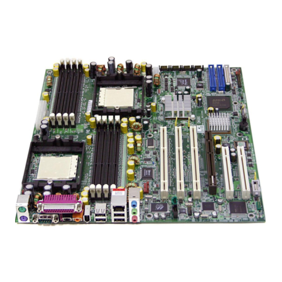
- Page 7 Chapter 1 Overview Overview Thank you for choosing this high performance motherboard. This is a dual AMD Opteron micro-Socket 940 motherboard (M/B) based on the EATX form factor and features the AMD® HyperTransport™ I/O Hub (8111) AMD HyperTransport PCI-X Tunnel chipset (8131) and the AMD®...
-
Page 8: 1: Overview
Overview DK8X Motherboard ENERAL AFETY RECAUTIONS Keep the area around the Server clean and free of clutter. Servers weigh a lot. They can average about 50 lbs. (~22.68 kg) When lifting the system, two people should lift slowly from opposite ends with their feet spread out to distribute the weight. - Page 9 Chapter 1 Overview Touch a grounded metal object before removing the board from the antistatic bag. Do not let components or PCBs come into contact with your clothing, which may retain a charge even if you are wearing a wrist strap. Handle a board by its edges only;...
- Page 10 If those options don't work for you, IWILL also provides some helpful resources to help you.
-
Page 11: Workstation Board Specification
Chapter 1 Overview TATION OARD PECIFICATIONS Processor 1. AMD® Dual Opteron Socket 940 CPUs 2. Supports 1.8 GHz or higher 3. HyperTransport™ of 6.4 GB/s bandwidth 4. Built-In Memory Controller Hub (MCH) Chipset 1. AMD® 8111 (HyperTransport I/O Hub) 2. AMD® 8151 (AGP Tunnel) 3. - Page 12 Audio Phone Jacks - Speaker Out, Mic In, Line-In. 1x IEEE-1394 port Center Out, Rear Out Hardware Monitor (CPU Thermal, Fan, Voltage, Intrusion) System Management WINBOND W83627THF 4Mb Flash EEPROM with AMI BIOS I2C support. SMBIOS 2.3 and DMI 2.0 compliant System BIOS Soft Power-Down Secure Boot, Multiple Boot support...
-
Page 13: Mainboard Map
Chapter 1 Overview AINBOARD ____________________________________________________________________________________________________________ Overview... - Page 14 DK8X Motherboard I/O A RRAY ________________________________________________________________________ Overview...
-
Page 15: 2: Hardware Installation
Chapter 2 Hardware Installation Hardware Installation In this section, we detail the procedures for how to install processors and other hardware components in your Mainboard. Please go to the specific sections to read more about section you are interested WARNING This motherboard contains sensitive electronic components that can be easily damaged by static electricity. -
Page 16: Map Of Jumpers
DK8X Motherboard AP OF UMPERS Refer to the following illustration to find the location of the Mainboard's jumpers ________________________________________________________________________ Hardware Installation... -
Page 17: Cn32: Clear Cmos Header
Chapter 2 Hardware Installation CN32: Clear CMOS Header The onboard button cell battery powers the CMOS RAM. It contains all the BIOS setup information. Keep the jumper connected to pins 1-2 (Default) to retain the RTC data as shown below. Normal (Default) Clear CMOS Under certain circumstances, you will need to reset system settings. - Page 18 DK8X Motherboard CN21: PCI 64-Bit Speed Select Jumper This header lets you determine the bus speed of the PCI-X 64-bit slots. The speed can be set to either 64 MHz (default) or 33 MHz 66MHz 33MHz CN25: PCI-X Speed Select Jumper This header lets you determine the bus speed of the PCI-X slots.
-
Page 19: J11: Audio For Front Panel
Chapter 2 Hardware Installation J11: Audio for Front Panel This jumper, J11, allows users to switch audio function to the front panel if front panel is installed. Pin Assignment: 1: MIC Out 2: GND 8: NC 5-6: Line Out Right 9-10: Line Out Left JP1: IEEE-1394 Enable/Disable This jumper allows users to enable/disable IEEE-1394 function of onboard header. - Page 20 DK8X Motherboard CN49, CN21: Chassis Intrusion Switch Connector This feature uses a mechanical switch on the chassis that connects to the chassis intrusion connector on the motherboard. The motherboard circuitry will detect the intrusion when the chassis cover is removed.
- Page 21 Chapter 2 Hardware Installation NSTALLING EMORY This Mainboard uses Dual Inline Memory Modules (DIMM). Eight DIMM socket memory banks are available, four memory bank for each CPU socket. The DIMM sockets accommodate 184-pin PC2100/PC2700 (DDR266/DDR333) and Double Data Rate (DDR) memory modules in 128MB, 256MB, 512MB, 1GB and 2GB size combinations. Total installed memory size is between a minimum of 128MB to a maximum of 16GB.
-
Page 22: Memory Installation Procedure
DK8X Motherboard Memory Installation Procedures This section outlines how to install Registered PC2100/PC2700 DDR DIMMs into the Mainboard. 1. Locate the Memory Bank on the Mainboard, where you will be installing the DIMMs. 2. Make sure the DIMM’s pins are facing down, and check that the pin arrangement on the memory module resembles the one pictured below. -
Page 23: Chapter 2 Hardware Installation
Chapter 2 Hardware Installation 3. Insert the module into the DIMM socket and press down evenly on both ends firmly until the DIMM module is securely in place. (The tabs of the DIMM socket will close-up to hold the DIMM in place when the DIMM is properly installed on the socket’s bottom.) 4. - Page 24 DK8X Motherboard ECOMMENDED EMORY ONFIGURATIONS The AMD Opteron processors have very specific memory module requirements, and due to the design of the Mainboard, there are certain configurations of memory that work best to make the most effective use of the memory bandwidth.
-
Page 25: Heatsink Installation
Chapter 2 Hardware Installation Heatsink Installation CAUTION: As with all computer equipment, the processor and motherboard components may be damaged by electrostatic discharge (ESD). Please take proper ESD precautions when handling any board. Warning: Do not apply voltage until the heatsink is fully installed. If voltage is applied before the heatsink is fully installed, the processor will overheat and failure will result. - Page 26 DK8X Motherboard Step 4 Step 5. Carefully place the retention frame Press firmly on the socket to ensure on the motherboard. proper contact of the backplate and The screw holes must align with the motherboard. backplate standoffs. Step 7 Step 6 Warning: Do not apply voltage until the heatsink is fully installed.
- Page 27 Chapter 2 Hardware Installation Step 8 Step 9 1. Gently push down on the processor while lowering the locking lever and latching it into the fully locked position. 2. Do not apply any power (voltage) to the system 1. The heatsink has a thermal interface material until the heatsink is fully installed.
- Page 28 DK8X Motherboard Step 12 Step 13 The spring clip must be installed as shown. 1. Make sure the retention clip is aligned with the plastic lug on the retention frame. 2. Carefully push straight down on the clip. This may take more force than the first side.
-
Page 29: Agp Pro Slot
Chapter 2 Hardware Installation AGP P The Mainboard does not feature an integrated video solution. Therefore, you will need to install a video card to use the Mainboard. The Accelerated Graphics Port Pro (AGP Pro) slot is specifically designed to support a new generation of AGP graphics cards with ultra-high memory bandwidths (up to 8x). -
Page 30: Eps12V Power Connectors
DK8X Motherboard EPS12V P OWER ONNECTORS Find the proper orientation of the connectors and push down firmly to make sure that the pins are aligned (the connector will only insert properly when properly aligned). The 8-pin connector is a dedicated power connector to supply power for the CPUs. For Wake on LAN support, the 5-volt Stand-by lead (+5VSB) from the ATX power supply must supply at least 2A. - Page 31 Chapter 2 Hardware Installation LOPPY RIVE ONNECTOR This 34-pin connector supports the standard floppy disk drive ribbon cable. Connect the single connector end to the Mainboard. Then, plug the other end of the ribbon into the floppy drive. Make sure you align the Pin 1 on the connector with the Pin 1 alignments on the Mainboard and the floppy drive.
-
Page 32: Front Panel Switches
DK8X Motherboard IMPORTANT Ribbon cables should always be connected with the red stripe on the Pin 1 side of the connector. IDE ribbon cables must be less than 46 cm (18 inches) long, with the second drive connector no more than 15 cm (6 inches) away from the first connector. - Page 33 Chapter 2 Hardware Installation Reset Switch (2-pin RST) This 2-pin connector connects to the chassis-mounted reset switch for rebooting your computer without turning your power switch off and on. This is a preferred method of rebooting your system to prolong the life of your system’s power supply. Hard Disk Activity LED (2-pin HDD_LED) This connector supplies power to the chassis's HDD/IDE activity LED.
-
Page 34: System Fan Connectors
DK8X Motherboard CPU/ S YSTEM ONNECTORS There are seven 3-pin fan connectors in the Mainboard motherboard. Two fans are used for CPU0 and CPU1; five are for system and front. These connectors support cooling fans of 500mA (6W) or less. Depending on the fan manufacturer, the wiring and plug may be different. -
Page 35: Rear Panel I/O Ports
Chapter 2 Hardware Installation I/O P ANEL ORTS This is an illustration of the Mainboard rear I/O port array PS/2 Mouse Connector (6-pin Female) The system will direct IRQ12 to the PS/2 mouse if one is detected. If no mouse is detected, IRQ12 will be free for expansion cards to use. - Page 36 DK8X Motherboard IEEE 1394/ FireWire Connector (6-pin Male) Depending on your Mainboard model, you may have one (1) onboard IEEE 1394 connector port for connecting FireWire devices. Refer to IEEE 1394 Ports & Header for more information. Serial Port (COM1) Connector (9-pin Male) The COM1 serial port can be used for pointing devices or other serial devices.
-
Page 37: Additional I/O Connectors
Chapter 2 Hardware Installation I/O C DDITIONAL ONNECTORS The Mainboard also contains connectors for adding additional ports and devices to the Mainboard. CD_In & Aux_In Audio Inputs (4-pin) There are both CD-In and Aux-In 4-pin connectors to connect your internal sound devices to the Sound Card. - Page 38 DK8X Motherboard IEEE 1394 (F ORTS AND EADER This Mainboard features an integrated Texas Instrument TSB43AB22 chip which supports two (2) IEEE 1394 (Firewire) ports. IEEE 1394 (FireWire) supports transfer rates of up to 400MB/s. One port is installed on the on-board I/O array, and a header completes the last port for external installation.
-
Page 39: Installing Expansion Cards
Chapter 2 Hardware Installation NSTALLING XPANSION ARDS This outlines the procedure for adding expansion cards to your Mainboard. Remember to read the documentation for your expansion cards and make the necessary hardware and software setting changes (i.e. jumper settings). The Mainboard features two (2) PCI-32 (32-bit, 33MHz) slots, one (1) PCI-64 (64-bit, 66/33MHz) slot and two (2) PCI-X (100/133MHz) slots to accommodate PCI expansion cards. -
Page 40: Silicon Image Chipset And Serial Ata
DK8X Motherboard ILICON MAGE HIPSET AND ERIAL The Serial version of this Mainboard is equipped with an integrated Silicon Image Sil3114 Serial ATA chipset. This chipset supports up to 4 SATA devices at transfer rates of up to 150MB/s. The Silicon Image Chipset also supports RAID configurations. RAID stands for "Redundant Array of Independent Devices"... - Page 41 Chapter 2 Hardware Installation OWERING ON YOUR YSTEM Follow these instructions to power on the computer after you have installed the Mainboard and all system devices. 1. Be sure that all switches are off (in some systems, Off is marked by “O”). 2.
-
Page 42: 3: Bios Setup
DK8X Motherboard BIOS Setup This chapter discusses the AMIBIOS Setup program built into the ROM BIOS. The Setup program allows users to modify the basic system configuration. The BIOS is the Basic Input / Output System used in all IBM PC, XT, AT, and PS/2 compatible computers. -
Page 43: Using The Bios Setup Utility
Chapter 3 BIOS Setup As the memory is being tested, you can access the BIOS Setup Utility by pressing the <F2> key when “Press < F2> to enter SETUP” appears briefly at the bottom of the screen. From the main menu of the BIOS Setup Utility, you can access the other setup screens, such as the Security and Power menus. - Page 44 DK8X Motherboard <F8> Key Load Failsafe Defaults <F9> Key Load Optimal Defaults <F10> Key Save and Exit Home Go to Top of Screen Go to Bottom of Screen Exit IMPORTANT The BIOS does NOT automatically save values that you have modified. If you do not save your values before you exit the BIOS Setup Utility, all your changes will be lost.
-
Page 45: Main Menu
Chapter 3 BIOS Setup Main Menu This is the first screen that is displayed when you enter the BIOS Setup Utility. Each tab lined on the top of the screen represents each different menu. The following picture shows the main menu. Main menu shows the information of BIOS version, date and ID; processor type, speed and count;... -
Page 46: Advanced Menu
DK8X Motherboard Advanced Menu This is the Advanced Menu screen. You can make these modifications on the Advanced menu. You can make these modifications on the Advanced Menu. Select the Submenus to modify those settings. Feature Option Description Disabled Select Floppy A or Floppy B 360 KB, 5 1/2”... - Page 47 Chapter 3 BIOS Setup Feature Option Description defined percentage when the temperature reaches a user defined value 3. H/W health event Enable: supports ACPI Aware O/S ACPI ACPI Configuration Yes/No Disable: doesn’t support ACPI Hyper Transport CPU0 : CPU1 HT Link Hyper Transport link...
-
Page 48: Ide Configuration Submenu
DK8X Motherboard IDE Configuration Submenu Feature Option Description Onboard PCI IDE Controller Disabled: disables integrated IDE controller Disabled Primary: enables only the Primary Primary IDE controller Secondary Secondary: enables only the Both secondary IDE controller Both: enables both controllers Disable/Enable device write Disabled protection. -
Page 49: Super Io Configuration Submenu
Chapter 3 BIOS Setup Select the time out value for IDE Detect Time Out (Sec) 0, 5, 10, 15, 20, 25, 30, 35 detecting ATA/ATAPI device Host & Device Select the mechanism for ATA(PI) 80Pin Cable Detection Host detecting 80 pin cable Device Super IO Configuration Submenu Feature... -
Page 50: Pcipnp Menu
DK8X Motherboard PCIPnP Menu ________________________________________________________________________ BIOS Setup... - Page 51 Chapter 3 BIOS Setup Feature Option Description Yes: lets the O/S configure PnP devices not required for Plug & Play O/S boot if your system has a Plug and Play O/S Value in units of PCI clocks 32, 64, 96, 128, 160, PCI Latency Timer for PCI device latency timer 192, 224, 248...
- Page 52 DK8X Motherboard Feature Option Description Available: specified IRQ is available to be used by Available PCI/PnP devices IRQ3~IRQ15 Reserved Reserve: specified IRQ is reserved for use by legacy ISA devices Available: specified DMA is available to be used by Available...
-
Page 53: Boot Menu
Chapter 3 BIOS Setup Boot Menu Feature Description Boot Device Priority Specify the boot device priority sequence Specify the boot device priority sequence Hard Disk Drives from available hard drives Specify the boot device priority sequence Removable Drives from available removable drives Specify the boot device priority sequence ATAPI CDROM Drives from available ATAPI CDROM drives... -
Page 54: Boot Setting Configuration Submenu
DK8X Motherboard Boot Setting Configuration Submenu Feature Option Description Disabled Allows BIOS to skip tests Quick Boot Enabled while booting Disabled: display normal Disabled Quiet Boot POST messages Enabled Enabled: display OEM logo Force BIOS Set display mode for option... - Page 55 Chapter 3 BIOS Setup Absent Enable/Disable all keyboards System Keyboard Present attached to the system Disabled Enable/Disable memory or Parity Check Enabled parity error check OS/2 compatibility mode Boot to OS/2 Disabled Wait for F1 key to be pressed Wait for “F1” if error Enabled if error occurs Disabled...
-
Page 56: Security Menu
DK8X Motherboard Security Menu Feature Option Description Install change Change User Password password Immediately clears the User Clear User Password password Setup: check password while invoking setup Password Check Always: check password while invoking setup as well as on each boot... -
Page 57: C H I P S E T M E N
Chapter 3 BIOS Setup Chipset Menu There are three submenus inside Chipset menu: NorthBridge Configuration, SouthBridge Configuration and AGP Configuration. NothBridge Configuration Submenu Memory Configuration Submenu ________________________________________________________________________ BIOS Setup 3-16... - Page 58 DK8X Motherboard Feature Option Description Interleaving allows memory accesses to be spread out Auto Bank Interleaving over BANKS on the same Disabled node, or across NODES, decreasing access contention Interleaving allows memory accesses to be spread out Auto Node Interleaving...
- Page 59 Chapter 3 BIOS Setup ECC Configuration Submenu Feature Option Description Master ECC Enables support Disabled Master ECC Enable on all nodes for ECC error Enabled detect and correction ________________________________________________________________________ BIOS Setup 3-18...
-
Page 60: Southbridge Configuration Submenu
DK8X Motherboard SouthBridge Configuration Feature Option Description Disabled 2.0 SM Bus Controller Enabled Auto causes hardware compensation vales. Other choices allow the user to Auto HT Link 0 P-Comp Mode override default Data HT Link 0 N-Comp Mode compensation with an... -
Page 61: Agp Configuration Submenu
Chapter 3 BIOS Setup AGP Configuration Submenu Feature Option Description 1x / 2x / 4x / 8x AGP Data Transfer Rate 1x / 2x / 4x Aperture size defines a Window into system memory 32, 64, 128, 256, 512, 1024, Aperture Size for the AGP video controller. -
Page 62: Apm Configuration Menu
DK8X Motherboard APM Configuration Menu ________________________________________________________________________ 3-21 BIOS Setup... -
Page 63: Exit Menu
Chapter 3 BIOS Setup Exit Menu Feature Description Exit system setup after saving the changes. Save Changes and Exit F10 key can be used for this operation Exit system setup without saving the Discard Changes and Exit changes. ESC key can be used for this operation Discard changes done so far to any of the Discard Changes... - Page 64 DK8X Motherboard Important: Driver Installation Procedure Please follow the installation procedure belows. 1. Install WindowsXP SP1a 2. Install 8151 driver: a. Install 8151 river from the following driver path: CD-ROM\Drivers\AMD\8151\setup.exe b. Update 8151 driver from the following driver path: CD-ROM\Drivers\AMD\8151\8151 v8.10\XP\English 3.
Need help?
Do you have a question about the DK8X and is the answer not in the manual?
Questions and answers