Table of Contents
Advertisement
Quick Links
Advertisement
Table of Contents

Related Manuals for IWILL DK8N


Summary of Contents for IWILL DK8N
- Page 1 I W I L L D K 8 N M o t h e r b o a r d U s e r ’ s M a n u a l FB25900000...
- Page 2 U s e r ’ s M a n u a l D K 8 N M o t h e r b o a r d...
- Page 3 P r e f a c e FCC Compliance Statement This equipment has been tested and found to comply with limits for a Class B digital device, pursuant to Part 15 of the FCC rules. These limits are designed to provide reasonable protection against harmful interference in residential installations.
- Page 4 This publication, including all photographs, illustrations and software, is protected under international copyright laws, with all rights reserved. Neither this manual, nor any of the material contained herein, may be re- produced without the express written consent of the manufacturer. IWILL ©Copyright 2004...
-
Page 5: Table Of Contents
Overview ................1-1 Package ..................1-1 Safety Notice ................1-2 DK8N Specification ..............1-5 Hardware Installation ..........2-1 Mainboard Map ................2-1 Jumper Setting ................2-2 Memory Installation Procedure ..........2-4 Heatsink and CPU Installation .......... - Page 6 U s e r ’ s M a n u a l D K 8 N M o t h e r b o a r d BIOS Setup ................. 3-1 Starting the BIOS Setup ............3-1 Using the BIOS Setup Utility ............ 3-2 Main Menu .................
-
Page 7: Package
Chapter 1 Package DK8N Motherboard 2 x SATA cable+1 x SATA power cable Rear panel I/O shield 3 jumper caps (Extra caps in case original caps get lost) CD (contains drivers and utilities) User’s manual ATA-66/100 IDE cable x 1... - Page 8 O v e r v i e w D K 8 N M o t h e r b o a r d YOU MUST HAVE ENOUGH SYSTEM INTEGRATION KNOWLEDGE BEFORE THE INSTALLATION General Safety Precautions Keep the area around the Server clean and free of clutter. Servers weigh a lot.
- Page 9 Chapter 1 Use a grounded wrist strap designed to prevent static discharge. Keep all components and printed circuit boards (PCBs) in their antistatic bags until ready for use. Touch a grounded metal object before removing the board from the antistatic bag. Do not let components or PCBs come into contact with your clothing, which may retain a charge even if you are wearing a wrist strap.
- Page 10 2. The FAQ (Frequently Asked Questions) sections in the IWILL website are often helpful since other users often have the same questions. 3. Email us at: support@iwill.net and we will try to answer your ques- tions within 5 business days.
-
Page 11: Dk8N Specification
Chapter 1 DK8N Specifications ® a. AMD Dual Opteron Socket 940 CPUs Processor b. Supports 1.8 GHz or higher a. nVidia nForce3 Pro 250 Chipset ® b. AMD 8131 (PCI-X Tunnel) a. 4 + 4 socket for 184-pin DDR DIMM sockets Memory b. - Page 12 O v e r v i e w D K 8 N M o t h e r b o a r d PS/2 mouse and keyboard connectors with Wake-Up function 1 x UART 16550 serial port (COM1) 1 x 25-pin parallel port with ECP/EPP support Rear Panel I/O 4 x USB 2.0 ports 1 x Gigabit Ethernet (RJ-45 port)
-
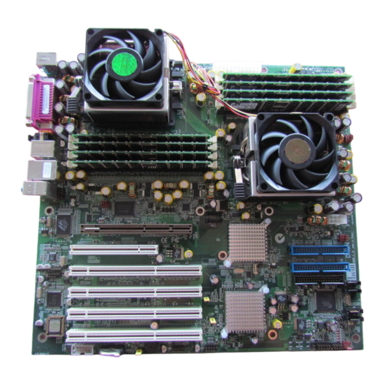
Page 13: Mainboard Map
Chapter 2 Mainboard Map CN44 CN32 CN21 CN25 CN48 CN806 J1 J2 CPU FAN... -
Page 14: Jumper Setting
H a r d w a r e I n s t a l l a t i o n D K 8 N M o t h e r b o a r d Jumper Setting CN32: Clear CMOS Header The onboard button cell battery powers the CMOS RAM. - Page 15 Chapter 2 CN21: PCI-X Speed Select Jumper This header lets you determine the bus speed of the PCI-X 64-bit slots. The speed can be set to either 64 MHz (default) or 33 MHz. 66MHZ 33MHZ CN25: PCI-X Speed Select Jumper This header lets you determine the bus speed of the PCI-X slots.
-
Page 16: Memory Installation Procedure
H a r d w a r e I n s t a l l a t i o n D K 8 N M o t h e r b o a r d Memory Installation Procedure Installing Memory This Mainboard uses Dual Inline Memory Modules (DIMM). - Page 17 Chapter 2 Memory Installation Procedure This section outlines how to install Registered PC3200/PC2700 DDR DIMMs into the Mainboard. 1. Locate the Memory Bank on the Mainboard, where you will be in- stalling the DIMMs. 2. Make sure the DIMM’s pins are facing down, and check that the pin arrangement on the memory module resembles the one pictured below.
- Page 18 H a r d w a r e I n s t a l l a t i o n D K 8 N M o t h e r b o a r d 3. Insert the module into the DIMM socket and press down evenly on both ends firmly until the DIMM module is securely in place.
- Page 19 Chapter 2 Recommended Memory Configurations The AMD Opteron processors have very specific memory module requirements, and due to the design of the Mainboard, there are certain configurations of memory that work best to make the most effective use of the memory bandwidth. The AMD Opteron features 128-bit DDR memory channels.
-
Page 20: Heatsink And Cpu Installation
2.The heatsink/fan assembly shown in this poster 2.Peel the release liner off the backplate may not exactly match the one provided in the DK8N Package. ® 3.The AMD Opteron processor heatsink re- quires the retention frame and the backplate to be attached to the motherboard. - Page 21 Chapter 2 Step 4 Step 5 Carefully place the retention frame on the Press firmly on the socket to ensure proper contact of the backplate and motherboard. motherboard. The screw holes must align with the backplate standoffs. Step 6 Step 7 Warning: Do not apply voltage until the heatsink is fully installed.
- Page 22 H a r d w a r e I n s t a l l a t i o n D K 8 N M o t h e r b o a r d Step 9 Step 8 1.Gently push down on the processor while low- ering the locking lever and latching it into the fully locked position.
- Page 23 Chapter 2 Step 12 Step 13 The spring clip must be installed as shown. 1.Make sure the retention clip is aligned with the plastic lug on the retention frame. 2.Carefully push straight down on the clip. This may take more force than the first side. Step 14 Step 15 The second type cooler installation Carefully...
-
Page 24: Agp Pro Slot
H a r d w a r e I n s t a l l a t i o n D K 8 N M o t h e r b o a r d The AGP Pro Slot The Mainboard does not feature an integrated video solution. Therefore, you will need to install a video card to use the Mainboard. -
Page 25: Connector Installation
Chapter 2 Connector Installation J11: Audio for Front Panel This jumper, J11, allows users to switch audio function to the front panel if front panel is installed. Pin Assignment: Pin 1 Audio VERF Pin 7 Mic-In L Pin 2 GND Pin 8 NC KEY Pin 3 Mic-In R Pin 9-10Line-Out L... -
Page 26: Eps12V Power Connectors
H a r d w a r e I n s t a l l a t i o n D K 8 N M o t h e r b o a r d EPS12V Power Connectors Find the proper orientation of the connectors and push down firmly to make sure that the pins are aligned (the connector will only insert properly when properly aligned). -
Page 27: Primary Ide Connectors
Chapter 2 Floppy Disk Drive Connector This 34-pin connector supports the standard floppy disk drive rib- bon cable. Connect the single connector end to the Mainboard. Then, plug the other end of the ribbon into the floppy drive. Make sure you align the Pin 1 on the connector with the Pin 1 alignments on the Mainboard and the floppy drive. - Page 28 H a r d w a r e I n s t a l l a t i o n D K 8 N M o t h e r b o a r d IMPORTANT Ribbon cables should always be connected with the red stripe on the Pin 1 side of the connector.
-
Page 29: Cn48 Front Panel Switches
Chapter 2 CN48 Front Panel Switches The front panel switches header connects the front control panel but- tons and LEDs to the Mainboard. Front Panel Switch Headers Speaker- Speaker+ Power on Power Led + Power Led - Power on + HDD Led - Reset Button Reset Button (2-pin RST) This 2-pin connector connects to the chassis-mounted reset switch... -
Page 30: Cpu/ System Fan Connectors
H a r d w a r e I n s t a l l a t i o n D K 8 N M o t h e r b o a r d CPU/ System Fan Connectors There are seven 3-pin fan connectors in the Mainboard motherboard. Two fans are used for CPU0 and CPU1;... -
Page 31: Rear Panel I/O Ports
Chapter 2 Rear Panel I/O Ports This is an illustration of the Mainboard rear I/O port array Mouse Parellet Pot IEEE1394 SPEAKER Mic in Keyboad Rear Out Ceter Out S/PDIF USB2.0 COM1 PS/2 Mouse Connector (6-pin Female) The system will direct IRQ12 to the PS/2 mouse if one is detected. If no mouse is detected, IRQ12 will be free for expansion cards to use. - Page 32 H a r d w a r e I n s t a l l a t i o n D K 8 N M o t h e r b o a r d IEEE 1394/ FireWire Connector (6-pin Male) Depending on your Mainboard model, you may have one (1) onboard IEEE 1394 connector port for connecting FireWire devices.
-
Page 33: Additional I/O Connectors
Chapter 2 Additional I/O Connectors The Mainboard also contains connectors for adding additional ports and devices to the Mainboard. CD_In Audio Inputs (4-pin) There is CD-In 4-pin connectors to connect your internal sound de- vices to the Sound Card. See Audio for setup information. 4-pin Onboard Audio Header Audio Pin Assignments Description... - Page 34 H a r d w a r e I n s t a l l a t i o n D K 8 N M o t h e r b o a r d USB 2.0 Ports and Header nVIDIA nForce3 250 Pro chip supports eight (8) USB 2.0 ports.
-
Page 35: Installing Expansion Cards
Chapter 2 Installing Expansion Cards This outlines the procedure for adding expansion cards to your Mainboard. Remember to read the documentation for your expansion cards and make the necessary hardware and software setting changes (i.e. jumper settings). The Mainboard features one (1) PCI-32 (32-bit, 33MHz) slots, two (2) PCI-X (64-bit, 66/MHz) slots and two (2) PCI-X (64/100MHz) slots or one (1) PCI-X (64/133MHz) to accommodate PCI expansion cards. -
Page 36: Silicon Image Chipset And Serial Ata
H a r d w a r e I n s t a l l a t i o n D K 8 N M o t h e r b o a r d J16, J17 SATA Connector From nVIDIA nForce3 Pro250 J1, J2, J3, J4 SATA Connector From SILICON-IMAGE Silicon Image Chipset and Serial ATA... - Page 37 Chapter 2 Powering on your System Follow these instructions to power on the computer after you have installed the Mainboard and all system devices. 1. Be sure that all switches are off (in some systems, Off is marked by “O”). 2.
-
Page 38: Bios Setup
B I O S S e t u p D K 8 N M o t h e r b o a r d BIOS Setup This chapter discusses the AMIBIOS Setup program built into the ROM BIOS. The Setup program allows users to modify the basic sys- tem configuration. -
Page 39: Using The Bios Setup Utility
Chapter 3 2. As the memory is being tested, you can access the BIOS Setup Util- ity by pressing the <F2> key when “Press < F2> to enter SETUP” appears briefly at the bottom of the screen. From the main menu of the BIOS Setup Utility, you can access the other setup screens, such as the Security and Power menus. - Page 40 B I O S S e t u p D K 8 N M o t h e r b o a r d <F8> Key Load Failsafe Defaults <F9> Key Load Optimal Defaults <F10> Key Save and Exit Home Go to Top of Screen Go to Bottom of Screen Exit...
-
Page 41: Main Menu
Chapter 3 Main Menu This is the first screen that is displayed when you enter the BIOS Setup Utility. Each tab lined on the top of the screen represents each different menu. The following picture shows the main menu. Main menu shows the information of BIOS version, date and ID;... -
Page 42: Advanced Menu
B I O S S e t u p D K 8 N M o t h e r b o a r d Advanced Menu This is the Advanced Menu screen. You can make these modifications on the Advanced Menu. Select the Submenus to modify those settings. - Page 43 Chapter 3 Feature Option Description defined percentage when the tempera- ture reaches a user defined value 3. H/W health event Enable: If O/S sup- ACPI Aware ACPI Configuration ports ACPI O/S Yes/No Disable: If O/S doesn’t support ACPI Hyper Transport link Hyper Transport CPU0: CPU1 HT Configuration...
-
Page 44: Ide Configuration Submenu
B I O S S e t u p D K 8 N M o t h e r b o a r d IDE Configuration Submenu You can also setup your PCI IDE controller on Advance menu. -
Page 45: Super Io Configuration Submenu
Chapter 3 Super IO Configuration Submenu Feature Option Description Allows BIOS to en- Onboard Floppy Disabled ab l e o r d i s ab l e Controller Enabled floppy controller Disabled Allows BIOS to en- 200/300, 200/330 Onboard Game/Midi ab l e o r d i s ab l e 208/300, 208/330 Port... -
Page 46: Pcipnp Menu
B I O S S e t u p D K 8 N M o t h e r b o a r d PCIPnP Menu... - Page 47 Chapter 3 Feature Option Description Yes: lets the O/S con- figure PnP devices not Plug & Play O/S required for boot if your system has a Plug and Play O/S Value in units of PCI 32, 64, 96, 128, 160, clocks for PCI PCI Latency Timer 192, 224, 248...
- Page 48 B I O S S e t u p D K 8 N M o t h e r b o a r d Feature Option Description Available: specified IRQ is available to be IRQ3,4,5,7,9, Available used by PCI/PnP de- 10,11,14,15 Reserved vices...
-
Page 49: Boot Menu
Chapter 3 Boot Menu Feature Description Boot Device Priority Specify the boot device priority sequence Specify the boot device priority sequence Hard Disk Drives from available hard drives Specify the boot device priority sequence Removable Drives from available removable drives Specify the boot device priority sequence CD/DVD Drives from available CD/DVD drives... -
Page 50: Boot Setting Configuration Submenu
B I O S S e t u p D K 8 N M o t h e r b o a r d Boot Setting Configuration Submenu Feature Option Description Disabled Allows BIOS to skip Quick Boot Enabled tests while booting Disabled: display nor- Disabled mal POST messages... - Page 51 Chapter 3 Disabled Wait for F1 key to be Wait for “F1” if error Enabled pressed if error occurs Display “Press DEL Hit ‘DEL’ Message Disabled t o r u n S e t u p ” i n Display Enabled POST Enabled: allows op-...
-
Page 52: Security Menu
B I O S S e t u p D K 8 N M o t h e r b o a r d Security Menu Feature Option Description Change User Install or change the Password password Immediately clears the User password Clear User Password Setup: check password... -
Page 53: Chipset Menu
Chapter 3 Chipset Menu There are three submenus inside Chipset menu: NorthBridge Configuration, SouthBridge Configuration and AGP Configuration. NorthBridge Configuration Submenu Memory Configuration Submenu 3-16... - Page 54 B I O S S e t u p D K 8 N M o t h e r b o a r d Feature Option Description Interleaving allows memory accesses to be Bank Interleaving Auto s p r e a d o u t o v e r Disabled BANKS on the same n o d e , o r a c r o s s...
- Page 55 Chapter 3 ECC Configuration Sub-submenu Feature Option Description Master ECC Enables Disabled support on all nodes Master ECC Enable Enabled for ECC error detect and correction 3-18...
-
Page 56: Southbridge Configuration Submenu
B I O S S e t u p D K 8 N M o t h e r b o a r d SouthBridge Configuration Submenu Feature Option Description E n ab l e o r D i s ab l e Disabled SMBus Controller SMBus Controller... - Page 57 Chapter 3 Enable or Disable IO Disabled Onboard IOAPIC APIC Enabled CPU0-LDT to CK8S 200~1000MHz Frequency Selection Frequency CPU0-LDT to CPU1 200~1000MHz Frequency Selection Frequency CPU0-LDT to PCI-X 200~1000MHz Frequency Selection Frequency Configuration nVidia RAID Rom Sub-submenu 3-20...
-
Page 58: Agp Configuration Submenu
B I O S S e t u p D K 8 N M o t h e r b o a r d AGP Configuration Submenu Feature Option Description Aperture size defines a Window into system 32, 64, 128, memory for the AGP Aperture Size 256, 512MB... -
Page 59: Pci-X Configuration Submenu
Chapter 3 PCI-X Configuration Submenu Feature Option Description Auto Mode Data HT Link Mode Calcomp+Data Calcomp-Data 3-22... -
Page 60: Exit Menu
B I O S S e t u p D K 8 N M o t h e r b o a r d Exit Menu Feature Description Exit system setup after saving the changes. Save Changes and Exit F10 key can be used for this opera tion Exit system setup without saving the changes. -
Page 61: Os And Driver Installation
Chapter 4 OS and driver Installation For the latest information, please check on our website http://www. iwill.net,or contact with our technicians.
Need help?
Do you have a question about the DK8N and is the answer not in the manual?
Questions and answers