
Related Manuals for Campbell COM220


Summary of Contents for Campbell COM220
- Page 1 COM220 Telephone Modem Revision: 3/15 C o p y r i g h t © 1 9 9 7 - 2 0 1 5 C a m p b e l l S c i e n t i f i c ,...
-
Page 3: Limited Warranty
Limited Warranty “Products manufactured by CSI are warranted by CSI to be free from defects in materials and workmanship under normal use and service for twelve months from the date of shipment unless otherwise specified in the corresponding product manual. (Product manuals are available for review online at www.campbellsci.com.) Products not manufactured by CSI, but that are resold by CSI, are warranted only to the limits extended by the original manufacturer. - Page 4 SCIENTIFIC, INC., phone (435) 227-9000. After an application engineer determines the nature of the problem, an RMA number will be issued. Please write this number clearly on the outside of the shipping container. Campbell Scientific’s shipping address is: CAMPBELL SCIENTIFIC, INC.
- Page 5 • Periodically (at least yearly) check electrical ground connections. WHILE EVERY ATTEMPT IS MADE TO EMBODY THE HIGHEST DEGREE OF SAFETY IN ALL CAMPBELL SCIENTIFIC PRODUCTS, THE CUSTOMER ASSUMES ALL RISK FROM ANY INJURY RESULTING FROM IMPROPER INSTALLATION, USE, OR MAINTENANCE OF TRIPODS, TOWERS, OR ATTACHMENTS TO TRIPODS AND TOWERS SUCH AS SENSORS, CROSSARMS, ENCLOSURES, ANTENNAS, ETC.
-
Page 7: Table Of Contents
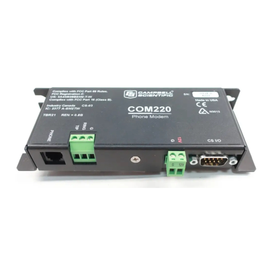
A. Changing COM220 Settings ........A-1 DIP Switch Settings ................ A-1 Hayes AT Commands ..............A-2 Downloading a New Operating System to the COM220 ....A-6 Program Examples ................A-7 A.4.1 ModemCallback Example (for CR1000) ......... A-7 A.4.2 DialModem Example (for CR1000) ........A-8 A.4.3 P97 Instruction (for CR10X) ........... - Page 8 Table of Contents Figures 1-1. COM220 DIP switches. Five screws and outer cover must be removed for access to DIP switches..........1 1-2. COM220 ....................2 3-1. CR1000 and COM220 using remote telephone line ......4 3-2. CR10X with CR10 wiring panel and COM220 using RJ11C telephone jack ..................
-
Page 9: Introduction
AT command set. Its primary use is as a remote-site phone modem connected to a CSI datalogger. The modem is powered and enabled by the battery- powered datalogger. When not active, the COM220 draws 100 to 120 µA from the datalogger’s 12-Vdc output. During a call, it draws about 30 mA. -
Page 10: Default Dip Switch Settings
, describes the CS I/O (p. B-1) interface. The COM220 can be used as an originate modem at the datalogger site. For newer PakBus dataloggers (for example, CR800, CR1000, CR3000), use the ModemCallback instruction or the DialSequence and DialModem instructions to program the datalogger to originate a call to the computer. -
Page 11: Computer Requirements
Weight: 0.16 kg (0.35 lb) Installation The COM220 is designed to be used with standard, analog telephone lines. It will not work with a digital telephone line. Connection to telephone company- provided coin service (central office implemented systems) is prohibited. -
Page 12: Cr1000 And Com220 Using Remote Telephone Line
21X(L) — serial number 13,442 or lower CR500 serial number 1764 or lower CR7, CR700X — serial number 2778 or lower 14-AWG Ground Wire (green with yellow stripe, if provided by CSI) FIGURE 3-1. CR1000 and COM220 using remote telephone line... -
Page 13: Connecting To Earth Ground
Connecting to Earth Ground Connect the 14-AWG grounding wire (green with yellow stripe, provided with the COM220) to the ground terminal (GND) on the COM220 and to the enclosure’s earth ground connection. If the site does not have a grounded enclosure, connect the ground wire directly to an earth ground connection. -
Page 14: Loggernet Setup
Edit Modem Database dialog box. Set the Maximum Baud Rate appropriate for your modem and datalogger. Click on the PhoneModem in your network map. Enter the COM220’s • analog phone number. -
Page 15: Telephone To Md485 Or Telephone To Rf Systems
MD485 should be set to the same baud rate. When using a PakBus network with a datalogger configured as a router, the COM220 can be set for SDC7 and the radio for SDC8, or vice versa. Contact a Campbell Scientific application engineer for more information. -
Page 16: Connecting To A Surge Protector
COM220 Telephone Modem Connecting to a Surge Protector Campbell Scientific offers two surge protectors (pn 4330 and 6362). The 4330 and 6362 are essentially the same, except that the 6362 has hardware for mounting to an enclosure backplate. NOTE The 4330 is also known as the 2374-01. -
Page 17: Modem Settings
FIGURE 3-4. Side view of surge-suppressor wiring Modem Settings The COM220 is shipped from the factory with default settings that support PakBus dataloggers (such as the CR800, CR1000, CR3000, and CR10XPB). The modem comes configured for synchronous device communication (SDC7), and, if using a PakBus datalogger, can answer a call as soon as a call is detected. -
Page 18: Troubleshooting
Switch Settings (p. A-1) 4) If the COM220 is set for modem enable (DIP switch 1 open) and you are unable to connect to the datalogger, try setting the datalogger ME baud rate, BaudrateME, to a negative number (for example, –9600) in order to... - Page 19 MD485, the RF401, the SC932A, and the PDA-to-CS I/O connector. 7) If the COM220 is in SDC mode (the default is SDC7, with DIP switch 1 closed and DIP switch 2 open), verify that any other SDC devices attached...
- Page 20 COM220 Telephone Modem To comply with FCC rules and regulations, all repairs on the COM220 modem must be performed by Campbell Scientific, Inc. or an authorized agent of Campbell Scientific, Inc. For assistance in installation or troubleshooting or for repairs, contact Campbell Scientific: Campbell Scientific, Inc.
-
Page 21: Changing Com220 Settings
1 must be open (that is, modem enable selected). DIP Switches 3 and 4: ME Baud Rates DIP switches 3 and 4 only have effect when the COM220 is in modem enable mode. If the COM220 is in ME mode, switches 3 and 4 select the baud-rate... -
Page 22: A.2 Hayes At Commands
SC532 or SC532A device. An SC12 cable must be connected to the peripheral port on the SC532 or SC532A and the CS I/O port on the COM220. Another cable should connect the RS232 port (if using an SC532 device) or the PC port (if using an SC532A device) to one of your computer’s serial ports. - Page 23 FIGURE A-1. COM220 to computer connection To configure the COM220 with Hayes AT commands, follow these steps: 1) Close DIP switch 8 on the COM220 (power to the COM220 must be cycled for about 5 sec before changes to DIP-switch settings are effective).
-
Page 24: Device Configuration Screen
7) Follow the instructions that appear in the terminal emulator screen (FIGURE A-3). 8) Be sure to save all new commands before exiting (by entering 5 and pressing Enter). 9) When finished, return DIP switch 8 on the COM220 to its open position. FIGURE A-2. Device Configuration screen... - Page 25 Appendix A. Changing COM220 Settings FIGURE A-3. Terminal Emulator screen in Device Configuration HAYES AT COMMAND SUMMARY: This manual does not attempt to be a primer on the Hayes AT command set. The commands are, therefore, only summarized below. For most applications, these commands will not need to be used.
-
Page 26: Downloading A New Operating System To The Com220
SC12 cable. If using an SC532, you will also have to apply 12 V to the COM220 via a green connector attached to a power supply. If using an SC532A device, power will be provided to the modem by the 12-V adapter connected to the SC532A. -
Page 27: A.4 Program Examples
Appendix A. Changing COM220 Settings FIGURE A-4. Send OS screen in Device Configuration A.4 Program Examples A.4.1 ModemCallback Example (for CR1000) The ModemCallBack instruction is available in the CR1000 with operating system std.12 or greater, in the CR3000 with operating system std.05 or greater, and in the CR800 or CR850 with operating system std.03 or greater. -
Page 28: Dialmodem Example (For Cr1000
Appendix A. Changing COM220 Settings A.4.2 DialModem Example (for CR1000) The program below does 2-min callbacks via the COM220 configured for SDC7. DialModem is set equal to a variable, so that the success/failure result can be used by the EndDialSequence instruction. If the call fails, the link will be terminated at the EndDialSequence instruction. -
Page 29: P97 Instruction (For Cr10X
“20” CONNECT7200 “21” CONNECT12000 “25” CONNECT14400 Hence, to work with the COM220, the user must put in a NULL string, or else the DialModem will fail unless, by chance, it returns the specific string the user entered. Therefore, it is highly recommended to use the “” string for... - Page 30 In the example below, the program does two minute data callbacks via the COM220 phone modem. Edit instruction 13 with your PC’s (LoggerNet’s) phone number. Remember to set switch 1 open for modem enable mode, and switches 3 and 4 open for 9600 baud.
-
Page 31: Example Programs For Data Callbacks Via A Cr1000 Datalogger Router
A.4.4 Example Programs for Data Callbacks via a CR1000 Datalogger Router To do data callbacks via a datalogger router with COM220 and RF401s or MD485s, they must all be configured to communicate with one another. In addition, two programs are necessary: one for the datalogger router and one for the remote datalogger. -
Page 32: Com220
Appendix A. Changing COM220 Settings Remote datalogger program for CR1000: 'Remote program for 2-min data callbacks via DL router with RF401 or MD485 link and COM220 link 'Datalogger router PakBusAdddress = 2 'LoggerNet server PakBusAddress = 4094 'Replace DialModem phone number with your PC's phone number... -
Page 33: Cs I/O Connection
2. (input) Ground 3. (output) Ring — A logic high signifies a ring signal has been detected. 4. (output) RX Data — Serial data from COM220 5. (input) Modem Enable — A logic high internally switches power to the modem. A logic low internally shuts off power to the modem. - Page 34 Appendix B. CS I/O Connection...
-
Page 35: Theory Of Operation
The COM220 is supplied with 12 V from the datalogger’s CS I/O connector or from the COM220’s external power connector. The 12 V is then regulated to +5 V to give power to the ring detect circuitry. -
Page 36: Theory Of Operation
Appendix C. Theory of Operation... -
Page 37: Fcc Warning To Users Of Class B Computing Devices
Appendix D. FCC Warning to Users of Class B Computing Devices WARNING This equipment generates, uses, and can radiate radio frequency energy and, if not installed and used in accordance with the instruction manual, may cause interference to radio communications. It has been tested and found to comply with the limits for a Class B computing device pursuant to Subpart J of Part 15 of... - Page 38 Appendix D. FCC Warning to Users of Class B Computing Devices...
-
Page 39: Ic Information
Appendix E. IC Information NOTE Industry Canada (IC) was formerly known as DOC. CP-01, Issue 8, Part I Section 14.1 “NOTICE: The Industry Canada label identifies certified equipment. This certification means that the equipment meets certain telecommunications network protective, operational and safety requirements as prescribed in the appropriate Terminal Equipment Technical Requirements document(s). - Page 40 Appendix E. IC Information...
- Page 42 • info@campbellsci.com.cn • info@campbellsci.de www.campbellsci.com www.campbellsci.de Campbell Scientific do Brasil Ltda. (CSB) Campbell Scientific Spain, S. L. (CSL Spain) Rua Apinagés, nbr. 2018 ─ Perdizes Avda. Pompeu Fabra 7-9, local 1 CEP: 01258-00 ─ São Paulo ─ SP 08024 Barcelona...
Need help?
Do you have a question about the COM220 and is the answer not in the manual?
Questions and answers