Table of Contents
Advertisement
Quick Links
Download this manual
See also:
Instruction Manual
Advertisement
Table of Contents

Related Manuals for Campbell 9522B


Summary of Contents for Campbell 9522B
- Page 1 9522B Iridium Satellite Modem & COM9522B Interface Modem November 2013 Copyright © 2009 - 2013 Campbell Scientific (Canada) Corp.
-
Page 2: Table Of Contents
Appendix B: Hardware Installation ..................28 9.1. SIM Card Installation ..................... 28 9.2. Antenna Installation ....................... 29 9.3. 9522B Modem Installation ..................... 31 Appendix C: Unlocking a SIM Card ................... 32 10.1. Handset Method ......................32 10.2. Terminal Emulator Method ..................32 Appendix D: Interfacing Loggernet to RUDICS .............. - Page 3 _____________________________________________________________________________ Disclaimer This manual addresses the concerns of interfacing another manufacturer’s product with Campbell Scientific Dataloggers. At the time of writing the information in this manual is currently accurate and up-to-date. However, changes to the manufacturer’s product are beyond our control. Such changes may affect equipment setup, configuration, and even safe use of the product.
-
Page 4: Overview
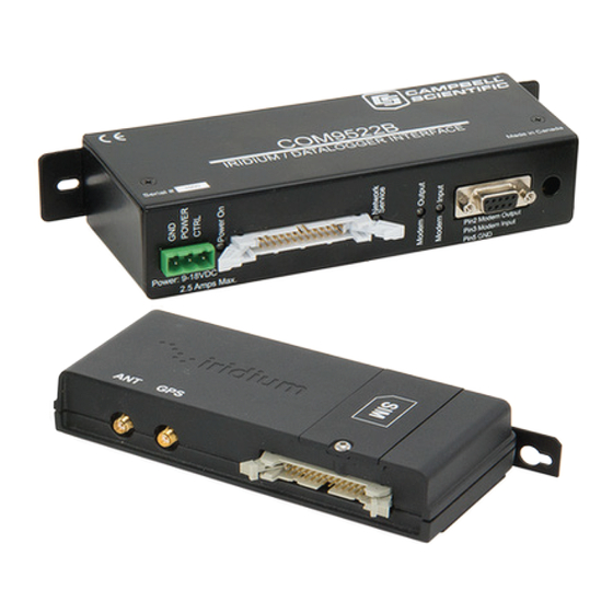
1.2. Modem Models and Accessories The Iridium Satellite System used with Campbell Scientific consists of the 9522B modem, COM9522B Interface Module kit, data cables, antenna and power supply. The base and remote stations utilize the same modem type, which both require a change to their configuration. -
Page 5: Hardware Overview
9522B Iridium Satellite Modem _____________________________________________________________________________ antenna cable. The antenna mounts to a ¾” diameter pipe which can be connected to a horizontal arm using a nu-rail connector. The nu-rail connector used will depend on the type of horizontal pipe. For a ¾” pipe, use #L1017, for a 1” pipe use #L1049. -
Page 6: Power Control
The COM9522B must draw power directly from a 12Vdc power supply (power +: Red, power -: Black) Figure 1: 9522B Base Station Configuration Figure 2: 9522B Remote Station RS232 Configuration... -
Page 7: Where It Works
9522B Iridium Satellite Modem _____________________________________________________________________________ Figure 3: 9522B Remote Station CS I/O Configuration 1.5. Where it works Unlike other satellite systems the Iridium satellite system is located in a low polar orbit, giving the system complete global coverage. Their relatively low altitude (780 km) means that they are situated close to transmitting modems and therefore require less transmission energy. -
Page 8: Com9522B Specifications
9522B Iridium Satellite Modem _____________________________________________________________________________ Mechanical Length: 162 mm Width: 81 mm Depth: 28 mm Weight: 420 g (approximate) 2.2. COM9522B Specifications Power Supply 9 – 18 VDC, 12VDC nominal, Operating: 32 mA (On State Max), 20 uA (Off State) -
Page 9: Setup Of Iridium Modems
Connect the COM9522B to the power supply. Be sure to connect the Yellow power control wire to +12V, so that the COM9522B will switch on power for the 9522B. 3.2.2. Step 2: Start Hyperterminal Open a new session of Hyperterminal from the Start Menu under: Start, All Programs, Accessories, Communications. -
Page 10: Step 3: Hyperterminal Connection Type
9522B Iridium Satellite Modem _____________________________________________________________________________ 3.2.3. Step 3: Hyperterminal Connection Type After clicking OK the next screen should resemble Figure 5. This screen allows you to select what type of connection you will establish. Figure 5: Hyperterminal Connection Type Click on the pull down tab next to the box marked ‘Connect using’. -
Page 11: Step 4: Hyperterminal Port Settings
9522B Iridium Satellite Modem _____________________________________________________________________________ 3.2.4. Step 4: Hyperterminal Port Settings As in Figure 7 this screen allows you to select the port settings required for communications between the Datalogger and modem. Figure 7: Hyperterminal Port Settings 3.2.5. Step 5: Configuring Port Settings... -
Page 12: Step 6: Hyperterminal Communications
9522B Iridium Satellite Modem _____________________________________________________________________________ Figure 8: Port Settings Configured 3.2.6. Step 6: Hyperterminal Communications Once you have clicked OK you should be connected to the modem (Figure 9). The counter in the bottom left hand corner of the screen will inform you that you are connected and begin counting up from 0. - Page 13 9522B Iridium Satellite Modem _____________________________________________________________________________ Type the following command string that correlates to the datalogger and/or Baud rate being used: CR1000: AT&F0 S0=1 &D0 +IPR=6,0 V0 &K0 &W0 &Y0 CR10X: AT&F0 S0=1 &D0 +IPR=5,0 V0 &K0 &W0 &Y0 The appropriate command string will need to be used in both modems.
- Page 14 9522B Iridium Satellite Modem _____________________________________________________________________________ To ensure that the settings have been stored in the modem type the command: AT&V The modem will return the following as seen in Figure 12 and should include the elements just added. Figure 12: Modem Setting Confirmation...
-
Page 15: Datalogger Configuration
9522B Iridium Satellite Modem _____________________________________________________________________________ 4. Datalogger Configuration To ensure proper communications with the datalogger it will be necessary to configure the datalogger. This can be done via the Device Configuration Utility. Follow the instructions provided to make a connection to the datalogger. -
Page 16: Loggernet Configuration
5.1. Setup of Loggernet Communications This Section deals with the proper software setup of a remote station that is making use of the COM9522B, in Campbell Scientific’s LoggerNet datalogger support software. All screenshots are based on the CR1000 datalogger. Please note that the array based dataloggers (i.e. -
Page 17: Step 2: Comport Configuration
9522B Iridium Satellite Modem _____________________________________________________________________________ Figure 15: LoggerNet Setup Tree 5.1.2. Step 2: ComPort Configuration With the Setup tree entered, you will now need to complete the configuration of each element. Start with selecting the ComPort element at the root of the tree (Figure 16). Be sure that the... -
Page 18: Step 3: Generic Modem Configuration
9522B Iridium Satellite Modem _____________________________________________________________________________ Figure 16: ComPort Configuration 5.1.3. Step 3: Generic Modem Configuration Select the Generic element as in Figure 17. Ensure that the Communications Enabled box is checked, change the Maximum Baud Rate to 19200 (9600 for a CR10X), add 3 seconds to the Extra Response Time, change the Maximum Packet Size to 1000, and add 200 ms to the Delay Hangup. -
Page 19: Step 4: Generic Modem Configuration Continued
9522B Iridium Satellite Modem _____________________________________________________________________________ Figure 17: Generic - Hardware Configuration 5.1.4. Step 4: Generic Modem Configuration Continued Click on the Modem tab located next to the Hardware tab (Figure 18). Set the RTS CTS Use to “3. The RTS line will be lowered”. -
Page 20: Step 5: Pakbusport Configuration
9522B Iridium Satellite Modem _____________________________________________________________________________ Figure 18: Generic - Modem Configuration 5.1.5. Step 5: PakBusPort Configuration As in Figure 19, be sure the Communications Enabled box is checked, change the Maximum Baud Rate to 19200 (9600 for a CR10X), set the Beacon Interval to all zeros, add 15 seconds of Extra Response Time and if present add a 200 ms delay under Delay Hangup . -
Page 21: Step 6: Cr1000 Configuration
9522B Iridium Satellite Modem _____________________________________________________________________________ Figure 19: PakBus Port Configuration 5.1.6. Step 6: CR1000 Configuration Be sure that the Communications Enabled box is checked and that the PakBus Address is correct for the datalogger being used. Add 200 ms under Delay Hangup (Figure 20). - Page 22 9522B Iridium Satellite Modem _____________________________________________________________________________ Figure 20: CR1000 Hardware Configuration Figure 21: CR1000 Schedule Configuration...
-
Page 23: Remote Modem Configuration
9522B Iridium Satellite Modem _____________________________________________________________________________ 6. Remote Modem Configuration As a matter of system redundancy it is recommended that the following programming be used as part of your datalogger program. If this programming is not used it is possible that the remote modem may lose it’s configuration. -
Page 24: Program Example 2
I/O port and the remainder of the time is used for actual communications. For details on programming for the CR10X contact Campbell Scientific. Please note that the interface between the CR10X and the COM9522B requires the use of SC932A CS I/O to RS232 DCE interface. -
Page 25: Troubleshooting Tools And Tips
9522B Iridium Satellite Modem _____________________________________________________________________________ If TimeIntoInterval (715,720,Min) Then PortSet (1,1) If TimeIntoInterval (10,720,Min) Then PortSet (1,0) 'Allow the modem 1 minute for warm up before sending settings. Once settings are 'sent to the modem allow another 4 minutes to ensure the modem is registered on 'the network before attempting communications. - Page 26 9522B Iridium Satellite Modem _____________________________________________________________________________ disable communications with your other stations when you attempt to download using Iridium. This can be accomplished in the Setup applet in LoggerNet. Finally, reboot LoggerNet to clear the communications queue of any tasks. Problem: Loggernet makes several attempts to connect to the remote station with no success.
-
Page 27: Appendix A: Sample Data Transfer Calculations
9522B Iridium Satellite Modem _____________________________________________________________________________ 8. Appendix A: Sample Data Transfer Calculations Note: calculations below based upon maximum theoretical throughputs. Real world transmission times for the Iridium Satellite Network have proven to be as much as twice as slow. When transmitting the data back from the station, the power consumption of the modem must be taken into account in order to avoid excessive discharge of the battery power supply. - Page 28 9522B Iridium Satellite Modem _____________________________________________________________________________ Power Calculation Note: When configuring a power supply (i.e. solar panel and battery) for a remote station it essential to design with the worst case scenario in mind. This will help to ensure that the station will perform as expected.
-
Page 29: Appendix B: Hardware Installation
9522B Iridium Satellite Modem _____________________________________________________________________________ 9. Appendix B: Hardware Installation The hardware shown in this Appendix consists only of hardware listed in Table 1. Although it may be possible to use other hardware, it will not be addressed in this Appendix. -
Page 30: Antenna Installation
9522B Iridium Satellite Modem _____________________________________________________________________________ Installed SIM Card Card Notch Figure24: Installed SIM Card 9.2. Antenna Installation These instructions apply to both the Base and Remote stations. This installation does not have to precede the modem installation. It should be conducted in the most convenient and logical order. - Page 31 Nu-rail is mounted to a ¾” by 6’ crossarm. It is also possible to use the 019WM or 019WMTOW, which are available from Campbell Scientific. These will allow you to mount the antenna to Campbell Scientific’s standard suite of tripods and towers.
-
Page 32: 9522B Modem Installation
Remote station. The modem installation should employ the following steps: Secure the L14394 mount and the 9522B interface in the enclosure in appropriate locations. Be sure to keep in mind all cable runs (i.e. antenna, power/control, and interface). -
Page 33: Appendix C: Unlocking A Sim Card
To unlock the Iridium SIM card permanently using the Iridium Handset follow these instructions. Install the SIM card, attach the antenna, and 9522B interface. Attach the handset as required. Apply power to the modem. The handset will request the PIN number before proceeding. - Page 34 9522B Iridium Satellite Modem _____________________________________________________________________________ Once the modem and terminal emulator are ready enter the following command: AT+CPIN? <Enter> The command requests that the modem respond as to whether a password is required. The expected modem response is: +CPIN: SIM PIN The response confirms that the SIM Card PIN1 code is required to unlock the Card.
-
Page 35: Appendix D: Interfacing Loggernet To Rudics
(also known as a serial port to telnet emulator software). Currently compatible software can be found here. The software version tested at Campbell and known to operate is version 2.6.1. http://www.fabulatech.com/serial-port-redirector.html Note: Campbell Scientific cannot guarantee that other versions of this software will operate as intended in this application. - Page 36 9522B Iridium Satellite Modem _____________________________________________________________________________ Figure 29: Serial Port Redirector Setup Next click on the Advanced button, and on the Protocol tab select Telnet. Click OK to create the new virtual serial port connection. And finally click the power button to enable the connection.
-
Page 37: Loggernet Setup
9522B Iridium Satellite Modem _____________________________________________________________________________ Figure 31: Serial Port Redirector Setup (cont’d) 11.4. Loggernet Setup Now that the serial port emulator has been configured, be sure to restart LoggerNet if running. Use the following steps to configure LoggerNet to dial the remote modem. -
Page 38: Step 2: Generic Modem Configuration
9522B Iridium Satellite Modem _____________________________________________________________________________ Figure 32: ComPort Configuration 11.4.2. Step 2: Generic Modem Configuration Add a new Generic Modem to the ComPort, select a Maximum Baud Rate of 115200 and Maximum Packet Size of 1024. - Page 39 9522B Iridium Satellite Modem _____________________________________________________________________________ Figure 33: Generic Modem Configuration In the Modem tab, add a dial script to instruct the RUDICS system to create a new connection to the remote modem. Use the following script to dial number the number of the modem to be contacted.
- Page 40 9522B Iridium Satellite Modem _____________________________________________________________________________ Figure 34: Generic Modem Configuration (cont’d) Finally add a PakBusPort Device and a logger and configure them according to the intended application (See Sections 5.1.5 & 5.1.6 for LoggerNet configuration details). Be sure to uncheck...
- Page 41 Campbell Scienti c (Canada) Corp. | 14532 131 Avenue NW | Edmonton AB T5L 4X4 | 780.454.2505 | www.campbellsci.ca AUSTRALIA | BRAZIL | CANADA | COSTA RICA | FRANCE | GERMANY | SOUTH AFRICA | SPAIN | UNITED KINGDOM | USA...
Need help?
Do you have a question about the 9522B and is the answer not in the manual?
Questions and answers