
Subscribe to Our Youtube Channel
Related Manuals for Campbell 9522B


Summary of Contents for Campbell 9522B
- Page 1 9522B Iridium Satellite Modem and COM9522B Interface Modem Revision: 9/16 C o p y r i g h t © 2 0 0 9 - 2 0 1 6 C a m p b e l l S c i e n t i f i c ,...
- Page 3 Quotations for repairs can be given on request. It is the policy of Campbell Scientific to protect the health of its employees and provide a safe working environment, in support of this policy a “Declaration of Hazardous Material and Decontamination”...
-
Page 5: About This Manual
PLEASE READ FIRST About this manual Please note that this manual was originally produced by Campbell Scientific Inc. primarily for the North American market. Some spellings, weights and measures may reflect this origin. Some useful conversion factors: Area: 1 in... - Page 7 • Periodically (at least yearly) check electrical ground connections. WHILE EVERY ATTEMPT IS MADE TO EMBODY THE HIGHEST DEGREE OF SAFETY IN ALL CAMPBELL SCIENTIFIC PRODUCTS, THE CUSTOMER ASSUMES ALL RISK FROM ANY INJURY RESULTING FROM IMPROPER INSTALLATION, USE, OR MAINTENANCE OF TRIPODS, TOWERS, OR ATTACHMENTS TO TRIPODS AND TOWERS...
-
Page 9: Table Of Contents
Hardware Overview ................2 Power Control ..................3 Where it Works ..................4 2. Specifications ............. 5 9522B Specifications ................5 COM9522B Specifications ..............5 3. Iridium SIM Card and Modem Setup ......5 Iridium SIM Card Use ................5 Setup of Iridium Modems .............. - Page 10 Figures 1-1. 9522B Base Station Configuration ............4 1-2. 9522B Remote Station RS-232 Configuration ........4 1-3. 9522B Remote Station CS I/O Configuration ........4 3-1. Starting a DevConfig Session .............. 6 3-2. Connected in DevConfig ..............7 3-3. CR1000 AT Command String ............. 8 3-4.
-
Page 11: Overview
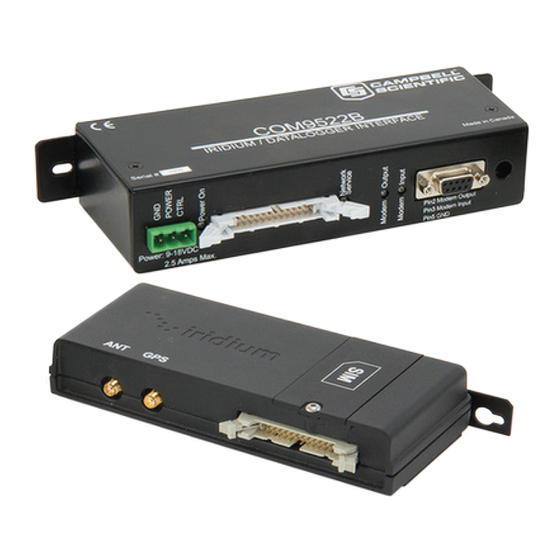
Modem Models and Accessories The Iridium satellite system used by Campbell Scientific consists of the 9522B modem, COM9522B interface module kit, data cables, antenna and power supply. The base and remote stations use the same modem type, which both require a change to their configuration. -
Page 12: Hardware Overview
9522B Iridium Satellite Modem and COM9522B Interface Modem TABLE 1-1. Equipment List for Base and Remote Stations Base Station Remote Station #30693 9522B L-Band Data Modem #30693 9522B L-Band Data Modem #30627 Mounting Kit #30741 Antenna #30741 Antenna #18017-L Antenna Cable... -
Page 13: Power Control
9522B Iridium Satellite Modem and COM9522B Interface Modem TABLE 1-2. Remote Station COM9522B Wiring Hardware ComPort Description Colour Connection “ANT” SMA connector to antenna Antenna cable using #18436 adaptor 9522B COM9522B Interface 26-pin ribbon cable connector Power Control Yellow Control Port Datalogger (5V power trigger) -
Page 14: Where It Works
9522B Iridium Satellite Modem and COM9522B Interface Modem FIGURE 1-1. 9522B Base Station Configuration FIGURE 1-2. 9522B Remote Station RS-232 Configuration FIGURE 1-3. 9522B Remote Station CS I/O Configuration Where it Works Unlike other satellite systems, the Iridium satellite network is located in a low polar orbit, giving the system complete global coverage. -
Page 15: Specifications
9522B Iridium Satellite Modem and COM9522B Interface Modem Specifications 9522B Specifications Power Supply for System (9522B and COM9522B) Off State: 20 uA Transmission Current: 500 mA @ 12 Vdc Operating: 4 to 32 Vdc, 333 mA @ 12 Vdc Standby:... -
Page 16: Setup Of Iridium Modems
COM9522B to a COM Port on your computer. Connect the COM9522B to the power supply. Be sure to connect the yellow power control wire to +12V, so that the COM9522B will switch on power for the 9522B. 3.2.2 Step 2: DevConfig Connection Open DevConfig. -
Page 17: Step 3: Devconfig Communications
9522B Iridium Satellite Modem and COM9522B Interface Modem 3.2.3 Step 3: DevConfig Communications Once you have clicked Connect, you should be connected to the modem (FIGURE 3-2). FIGURE 3-2. Connected in DevConfig Type the following command string that correlates to the datalogger and/or Baud rate being used: CR1000: AT&F0 S0=1 &D0 +IPR=6,0 V0 &K0 &W0 &Y0... -
Page 18: Cr1000 At Command String
9522B Iridium Satellite Modem and COM9522B Interface Modem FIGURE 3-3. CR1000 AT Command String The modem should add a 0 at the end of the command string (FIGURE 3-4). FIGURE 3-4. Modem Reply to Command String... -
Page 19: At&V Command
9522B Iridium Satellite Modem and COM9522B Interface Modem To ensure that the settings have been stored in the modem type the command: AT&V. FIGURE 3-5. AT&V Command The modem will return the following as seen in FIGURE and should include the elements just added. -
Page 20: Datalogger Configuration
9522B Iridium Satellite Modem and COM9522B Interface Modem This is a summary of the currently active modem profile and ensures that when power is cycled to the modem it will have the correct auto-answer, DTR, and flow control settings. Exit Hyperterminal and save your settings for later. -
Page 21: Loggernet Configuration
9522B Iridium Satellite Modem and COM9522B Interface Modem FIGURE 4-2. ComPorts Settings Tab LoggerNet Configuration Setup of LoggerNet Communications This section deals with the proper software setup of a remote section that uses the COM9522B in Campbell Scientific’s LoggerNet datalogger support software. -
Page 22: Step 1: Loggernet Setup
9522B Iridium Satellite Modem and COM9522B Interface Modem 5.1.1 Step 1: LoggerNet Setup Start LoggerNet and open the Setup screen from the Main category of the toolbar. Start the configuration by clicking on the Add Root button. From the Add submenu make the following selections: ... -
Page 23: Step 2: Comport Configuration
9522B Iridium Satellite Modem and COM9522B Interface Modem 5.1.2 Step 2: ComPort Configuration With the setup tree entered, you will now need to complete the configuration of each element. Start with selecting the ComPort element at the root of the tree (FIGURE 5-2). -
Page 24: Step 3: Generic Modem Configuration
9522B Iridium Satellite Modem and COM9522B Interface Modem 5.1.3 Step 3: Generic Modem Configuration Select the Generic element as in FIGURE 5-3. Ensure that the Communications Enabled box is checked, change the Maximum Baud Rate to 19200 (9600 for a CR10X), set the Extra Response Time to 3 seconds, change the Maximum Packet Size to 1000, and set the Delay Hangup to 200 ms. -
Page 25: Step 4: Generic Modem Configuration Continued
9522B Iridium Satellite Modem and COM9522B Interface Modem 5.1.4 Step 4: Generic Modem Configuration Continued Click on the Modem tab located next to the Hardware tab (FIGURE 5-4). Set the RTS CTS Use to “3. The RTS line will be lowered”. -
Page 26: Step 5: Pakbusport Configuration
9522B Iridium Satellite Modem and COM9522B Interface Modem 5.1.5 Step 5: PakBusPort Configuration As shown in FIGURE 5-5, select the PakBusPort. Be sure the Communications Enabled box is checked, change the Maximum Baud Rate to 19200 (9600 for a CR10X), set the Beacon Interval to 0, set the Extra Response Time to 15 seconds, and, if present, set the Delay Hangup to 200 ms. -
Page 27: Step 6: Cr1000 Configuration
9522B Iridium Satellite Modem and COM9522B Interface Modem 5.1.6 Step 6: CR1000 Configuration Select your datalogger as shown in FIGURE 5-6. Be sure that the Communications Enabled box is checked and that the PakBus Address is correct for the datalogger being used. Set the Delay Hangup to 200 ms. -
Page 28: Remote Modem Configuration
9522B Iridium Satellite Modem and COM9522B Interface Modem FIGURE 5-7. CR1000 Schedule Configuration Remote Modem Configuration As a matter of system redundancy, it is recommended that the following programming be used as part of your datalogger program. If this programming is not used, it is possible that the remote modem may lose its configuration. -
Page 29: Program Example 1
9522B Iridium Satellite Modem and COM9522B Interface Modem Program Example 1 In example 1, the station is a solar powered site where power management is a concern. Modem power is controlled by the COM9522B via control port 1. During this time, the modem is sent its configuration via the RS-232 port and the remainder of the time is used for actual communications. -
Page 30: Program Example 2
During this time, the modem is sent its configuration via the CS I/O port and the remainder of the time is used for actual communications. For details on programming for the CR10X, contact Campbell Scientific. Please note that the interface between the CR10X and the COM9522B requires the use of SC932A CS I/O to RS-232 DCE interface. -
Page 31: Troubleshooting Tools And Tips
9522B Iridium Satellite Modem and COM9522B Interface Modem Troubleshooting Tools and Tips Problem: I have intermittent successful connections between the remote and base station modem. The signal strength is weak and the data transfer speeds are slow. Solution: The antenna may not have a complete 180° view of the sky. Some objects and debris such as snow and trees can interfere with communications. - Page 32 9522B Iridium Satellite Modem and COM9522B Interface Modem...
-
Page 33: Sample Data Transfer Calculations
Appendix A. Sample Data Transfer Calculations The calculations below are based upon maximum theoretical NOTE throughputs. Real world transmission times for the Iridium Satellite Network have proven to be as much as twice as slow. When transmitting the data back from the station, the power consumption of the modem must be taken into account in order to avoid excessive discharge of the battery power supply. - Page 34 Appendix A. Sample Data Transfer Calculations Power Calculation When configuring a power supply (that is, solar panel and battery) NOTE for a remote station, it is essential to design with the worst case scenario in mind. This will help to ensure that the station will perform as expected.
-
Page 35: Hardware Installation
Appendix B. Hardware Installation The hardware shown in this appendix consists only of hardware listed in TABLE 1-1. Although it may be possible to use other hardware, it will not be addressed in this appendix. WARNING Do not connect power to either modem until installation is complete, as damage to the equipment may occur. -
Page 36: Antenna Installation
Appendix B. Hardware Installation Installed SIM Card Card Notch FIGURE B-3. Installed SIM Card B.2 Antenna Installation These instructions apply to both the base and remote stations. This installation does not have to precede the modem installation. It should be conducted in the most convenient and logical order. -
Page 37: B-4. Antenna, Mount, And Cable
Appendix B. Hardware Installation FIGURE B-4. Antenna, Mount, and Cable Thread the antenna onto the 3/4 inch supplied nut, being sure not to cross the threads (FIGURE B-5). FIGURE B-5. Antenna Attached to Mount... -
Page 38: 9522B Modem Installation
The modem installation should employ the following steps: Secure the #30627 mount to the 9522B interface. Secure this assembly in the enclosure in an appropriate location. Be sure to keep in mind all cable runs (that is, antenna, power/control, and interface). -
Page 39: Unlocking A Sim Card
To unlock the Iridium SIM card permanently using the Iridium Handset, follow these instructions. Install the SIM card. Attach the antenna and 9522B interface. Attach the handset as required. Apply power to the modem. The handset will request the PIN number before proceeding. Once you enter the PIN number (default 1111), the modem will register itself. - Page 40 Appendix C. Unlocking a SIM Card The next step is to enter the PIN code for the SIM card. AT+CPIN=”1111” <Enter> The modem should respond with an “OK” which means the PIN code has been accepted. This explanation assumes that the default code of “1111” is being used.
-
Page 41: Interfacing Loggernet To Rudics
Appendix D. Interfacing LoggerNet to RUDICS Contact Campbell Scientific if you are interested in using RUDICS. D.1 Base Station System Requirements LoggerNet software version 4.0 or greater Telnet-compliant serial port redirector software Iridium service account, supplied by Iridium service provider. You will also need to make arrangements with service provider to access the RUDICS network. -
Page 42: Serial Port Redirector Setup
Appendix D. Interfacing LoggerNet to RUDICS Serial Port window, select an unused serial port, and add the IP address and port number to connect to. FIGURE D-1. Serial Port Redirector Setup Next, click on the Advanced button, and on the Protocol tab, select Telnet. Click OK to create the new virtual serial port connection. -
Page 43: Loggernet Setup
Appendix D. Interfacing LoggerNet to RUDICS FIGURE D-3. Serial Port Redirector Setup (cont’d) D.4 LoggerNet Setup Now that the serial port emulator has been configured, be sure to restart LoggerNet if running. Use the following steps to configure LoggerNet to dial the remote modem. -
Page 44: Step 2: Generic Modem Configuration
Appendix D. Interfacing LoggerNet to RUDICS D.4.2 Step 2: Generic Modem Configuration Add a new Generic modem to the ComPort, select a Maximum Baud Rate of 115200 and Maximum Packet Size of 1024. FIGURE D-5. Generic Modem Configuration In the Modem tab, add a Dial Script to instruct the RUDICS system to create a new connection to the remote modem. -
Page 45: Generic Modem Configuration (Cont'd
Appendix D. Interfacing LoggerNet to RUDICS FIGURE D-6. Generic Modem Configuration (cont’d) Finally, add a PakBusPort and a datalogger and configure them according to the intended application (see Section 5.1.5, Step 5: PakBusPort Configuration , and Section 5.1.6, Step 6: CR1000 Configuration , for LoggerNet (p. - Page 46 Appendix D. Interfacing LoggerNet to RUDICS...
- Page 48 Santo Domingo, Heredia 40305 SOUTH AFRICA COSTA RICA • cleroux@csafrica.co.za • info@campbellsci.cc www.campbellsci.co.za www.campbellsci.cc Campbell Scientific Southeast Asia Co., Ltd. Campbell Scientific Ltd. 877/22 Nirvana@Work, Rama 9 Road Campbell Park Suan Luang Subdistrict, Suan Luang District 80 Hathern Road Bangkok 10250...
Need help?
Do you have a question about the 9522B and is the answer not in the manual?
Questions and answers