
Related Manuals for Campbell COM200


Summary of Contents for Campbell COM200
- Page 1 COM200 TELEPHONE MODEM INSTRUCTION MANUAL REVISION: 5/01 COPYRIGHT (c) 1997-2001 CAMPBELL SCIENTIFIC, INC.
- Page 2 This is a blank page.
- Page 3 CAMPBELL SCIENTIFIC, INC. CAMPBELL SCIENTIFIC, INC. will return such products by surface carrier prepaid. This warranty shall not apply to any CAMPBELL SCIENTIFIC, INC. products which have been subjected to modification, misuse, neglect, accidents of nature, or shipping damage. This warranty is in lieu of all other warranties, expressed or implied, including warranties of merchantability or fitness for a particular purpose.
- Page 4 This is a blank page.
-
Page 5: Table Of Contents
Appendixes A. Modifying the Non-Volatile Memory...... A-1 A.1 Hardware Connection to COM200............A-1 A.2 Remote Communication to the COM200..........A-1 A.3 Hayes at Command Summary............. A-3 B. CS I/O Connection ..........B-1 B.1 CS I/O 9 Pin Connection ..............B-1 C. -
Page 6: List Of Figures
RJ11C Telephone Jack ................A-2 A-2 COM200 to Computer Connection .............A-2 B-1 CS I/O Pin Out..................B-1 List of Tables 1 Dataloggers that Require Direct 12 VDC Connection to COM200 .... 3 F-1 Dataloggers that Require Direct 12 VDC Connection to COM200 ..F-1... -
Page 7: Introduction
Campbell Scientific products. This is not an RS-232 connection. Appendix B describes the configuration of this connector. The COM200 can be used as an originate modem at the datalogger site. To originate a call to the computer, the datalogger is programmed using Instruction 97. -
Page 8: Installation
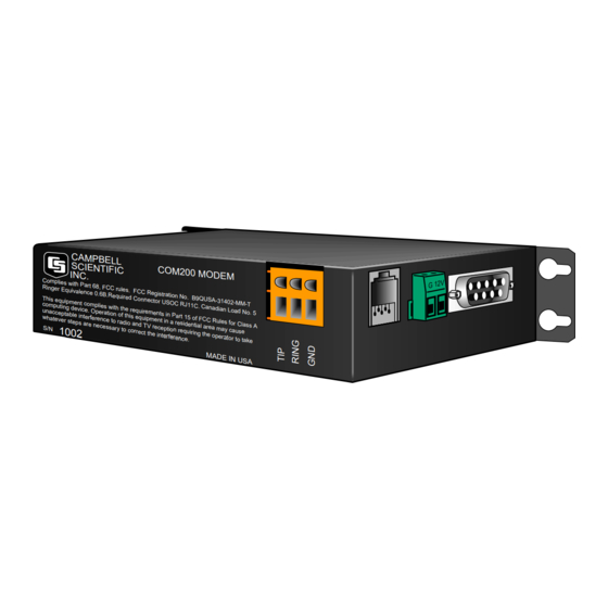
1 0 0 2 FIGURE 1. COM200 3. Installation The COM200 is designed to be used with standard analog telephone lines. It will not work with a digital telephone line. Connection to telephone company- provided coin service (central office implemented systems) is prohibited. -
Page 9: Connecting To Earth Ground
BDR301 and BDR320 3.2 Connecting to Earth Ground Connect the green 14 awg grounding wire (provided with the COM200) to the grounding terminal (GND) on the COM200 and to the enclosure’s earth ground connection. If the site does not have a grounded enclosure, then connect the ground wire directly to an earth ground connection. -
Page 10: Cr10X With Cr10X Wiring Panel And Com200 Using Remote Telephone Line
To E a rth G r ound Transient P r otector ( M o del 6 3 6 2 or 2 3 7 2 - 0 1 ) FIGURE 2. CR10X with CR10X Wiring Panel and COM200 Using Remote Telephone Line... -
Page 11: Cr10X With Cr10 Wiring Panel And Com200 Using
0 0 0 2 M A D E I N U S A R E N = 0 . 5 Tel e phone W a l l J a ck FIGURE 3. CR10X with CR10 Wiring Panel and COM200 Using RJ11C Telephone Jack... -
Page 12: Troubleshooting
If not, contact your local telephone company. If you can make a call out but the connection is poor or faint, contact your local telephone company. Verify the COM200 is receiving 12 VDC. If the COM200 is receiving 12 VDC from a separate power supply instead of the datalogger, is the ground of the separate power supply connected to the datalogger’s... -
Page 13: Modem Settings In Non-Volatile Memory
This option is used when the modem is sharing a line and you only want it to answer after a specified number of rings. For example, the COM200 is sharing a line with people at an office. It can be programmed to only answer after the 4 ring. - Page 14 COM200 Telephone Modem This is a blank page.
-
Page 15: Modifying The Non-Volatile Memory
Appendix A. Modifying the Non-Volatile Memory To modify the COM200’s settings, one must communicate directly to the COM200. This may be accomplished by using one of the two methods below. CAUTION Changing some of the modem's settings may result in communication problems. - Page 16 Appendix A. Modifying the Non-Volatile Memory C Cable FIGURE A-1. COM200 to Computer Connection C Cable Adaptor FIGURE A-2. CR10X with CR10 Wiring Panel and the old COM200...
-
Page 17: Hayes At Command Summary
Appendix A. Modifying the Non-Volatile Memory Example Program 1 *Table 1 Program 01: 1 Execution Interval (seconds) 1: Initiate Telecommunications (P97) 1: 02 RF Modem/9600 Baud 2: 1 Disabled when User Flag 1 is High 3: 20 Seconds Call Time Limit 4: 0 Seconds Before Fast Retry 5: 0... - Page 18 It is possible in some conditions to allow more than four rings. Consult a Campbell Scientific applications engineer about optimizing modem negotiations before trying this and be sure to try the set up locally before...
-
Page 19: Cs I/O Connection
0 V for logic low, 5 V for logic high. FIGURE B-1. CS I/O Pin Out (input) +5 VDC supply. Not used by COM200. (input) Ground (output) Ring - a logic high signifies a ring signal has been detected... - Page 20 This is a blank page.
-
Page 21: Theory Of Operation
Appendix C. Theory of Operation C.1 Theory of Operation The COM200 modem is used to transmit data over bandwidth-limited channels such as telephone lines by modulating audio tones, using Phase Shift Keying (PSK) at 9600 or 1200 baud and Frequency Shift Keying (FSK) at 300 baud. - Page 22 This is a blank page.
-
Page 23: Fcc Warning To Users Of
Appendix D. FCC Warning to Users of Class A Computing Devices WARNING This equipment generates, uses, and can radiate radio frequency energy, and if not installed and used in accordance with the instruction manual, may cause interference to radio communications. It has been tested and found to comply with the limits for a Class A computing device pursuant to Subpart J of Part 15 of... - Page 24 This is a blank page.
-
Page 25: Ic Information
Appendix E. IC Information NOTE Industry Canada (IC) was formally known as DOC. CP-01, Issue 8, Part I Section 14.1 “ NOTICE: The Industry Canada label identifies certified equipment. This certification means that the equipment meets certain telecommunications network protective, operational and safety requirements as prescribed in the appropriate Terminal Equipment Technical Requirements document(s). - Page 26 This is a blank page.
-
Page 27: The 10704 12 V Adaptor
VDC on the 9 pin connector and hence require a direct 12 VDC connection to the COM200. When using the 10704 adaptor, the red and black wires should be connected to 12 V and Ground, respectively. The female connector of the 10704 should be connected to the COM200 while the male connector goes to the datalogger. - Page 28 This is a blank page.
Need help?
Do you have a question about the COM200 and is the answer not in the manual?
Questions and answers