
Related Manuals for Campbell COM210


Summary of Contents for Campbell COM210
- Page 1 COM210 Telephone Modem Revision: 10/05 C o p y r i g h t ( c ) 1 9 9 7 - 2 0 0 5 C a m p b e l l S c i e n t i f i c , I n c .
- Page 2 CAMPBELL SCIENTIFIC, INC. CAMPBELL SCIENTIFIC, INC. will return such products by surface carrier prepaid. This warranty shall not apply to any CAMPBELL SCIENTIFIC, INC. products which have been subjected to modification, misuse, neglect, accidents of nature, or shipping damage. This warranty is in lieu of all other warranties, expressed or implied, including warranties of merchantability or fitness for a particular purpose.
-
Page 3: Table Of Contents
COM210 Telephone Modem Table of Contents PDF viewers note: These page numbers refer to the printed version of this document. Use the Adobe Acrobat® bookmarks tab for links to specific sections. 1. Introduction..............1 1.1 General Description ..................1 1.2 Computer Requirements ................1 2. -
Page 4: List Of Figures
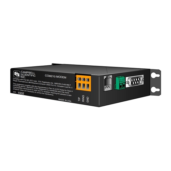
COM210 Telephone Modem Table of Contents List of Figures 1. COM210 ....................1 2. CR1000 and COM210 Using Remote Telephone Line ......4 3. CR10X with CR10 Wiring Panel and COM210 Using RJ11C Telephone Jack................5 A-1. LoggerNet Screen ................A-2 A-2. -
Page 5: Introduction
The COM210 is connected to a CSI datalogger by using a 9-pin subminiature D connector cable. This is the same 9-pin CS I/O connection common to all Campbell Scientific dataloggers (except the CR200 series). This is not an RS- 232 connection. Appendix B describes the configuration of this connector. -
Page 6: Specifications
COM210 Telephone Modem 2. Specifications • Bell 212A, CCITT V.22, and CCITT V.32 compatible • Full duplex at 9600 (default setting) and 1200 baud to datalogger • V.42 LAPM and MNP2-4 error correction • Hayes AT command set • On-board speaker •... -
Page 7: Connecting To Earth Ground
COM210 Telephone Modem Current Campbell Scientific dataloggers provide 12 VDC to the COM210 via the SC12 cable (Figure 2). Older dataloggers do not provide 12 VDC on the datalogger's CS I/O 9 pin connector. When used with the older dataloggers listed in Table1, 12 VDC and ground need to be connected via the green power connector on the side of the COM210 (see Figure 3). - Page 8 COM3 COM4 Rx Tx Rx Tx Rx Tx Rx CS I/O PERIPHERAL PORT MADE IN USA CAMPBELL COM210 MODEM SC12 Cable SCIENTIFIC INC. Complies with Part 68, FCC rules. FCC Registration No. B9QUSA-75378-MM-T Ringer Equivalence 0.9B. Required Connector USOC RJ11C.
- Page 9 L AG H L AG E3 AG G G G G G 12V SERIAL I/O 12V 12V POWER 9 10 SWITCHED CAMPBELL CR10 SCIENTIFIC INC. MADE IN USA SWITCHED WIRING PANEL NO. EARTH CONTROL AG H L AG H L AG H...
-
Page 10: Troubleshooting
COM210 Telephone Modem 4. Troubleshooting When the Campbell Scientific software cannot establish a link to the remote datalogger that is connected to the COM210, check the following: Verify the modem initialization settings have been changed for the specific calling modem on the computer. See software manual and/or help screens for more information. -
Page 11: Modem Settings In Non-Volatile Memory
COM210 Telephone Modem To comply with FCC rules and regulations, all repairs on the COM210 modem must be performed by Campbell Scientific, Inc. or an authorized agent of Campbell Scientific, Inc. For assistance in installation, troubleshooting, or for repair, contact Campbell Scientific: Campbell Scientific, Inc. - Page 12 COM210 Telephone Modem...
-
Page 13: Modifying The Non-Volatile Memory
After changing the settings, try the modem locally before installing it at a remote location. To speed problem resolution when contacting Campbell Scientific for support, please inform us of any modem setting changes that have been made. A.1 Hardware Connection to COM210 Connect the COM210 to a computer using an SC532A interface (Figure A-2). -
Page 14: Remote Communication To The Com210
Appendix A. Modifying the Non-Volatile Memory FIGURE A-1. LoggerNet Screen A.2 Remote Communication to the COM210 To remotely communicate with the COM210, program the datalogger to initiate a call to it using a program similar to the Example Program 1.* After this program runs once, the modem is now programmed and the actual program one wants to run may now be downloaded to the datalogger. - Page 15 Appendix A. Modifying the Non-Volatile Memory Logan, Utah SC532A RS232 to CS I/O MADE IN USA POWER To 12V To GND Black SC12 Cable CA MP BE LL 1 0 0 2 FIGURE A-2. COM210 to Computer Connection Example Program 1 *Table 1 Program 01: 1 Execution Interval (seconds)
-
Page 16: Hayes At Command Summary
Appendix A. Modifying the Non-Volatile Memory 3: Extended Parameters (P63) 1: 48 Option ;0 2: 68 Option ;D 3: 84 Option ;T 4: 13 Option 5: 00 Option 6: 00 Option 7: 00 Option 8: 00 Option After sending above program, disconnect from datalogger and wait 30 seconds, allowing program to finish, before connecting again. - Page 17 It is possible in some conditions to allow more than three rings. Consult a Campbell Scientific applications engineer about optimizing modem negotiations before trying this and be sure to try the set up locally before installing at a remote...
- Page 18 Appendix A. Modifying the Non-Volatile Memory This is a blank page.
-
Page 19: Cs I/O Connection
Appendix B. CS I/O Connection B.1 CS I/O 9-Pin Connection The pin out of the connector is shown in Figure B-1. The direction of the signal relative to the modem is shown in parenthesis. Unless specified otherwise, all levels are 0 V for logic low, 5 V for logic high. FIGURE B-1. - Page 20 This is a blank page.
-
Page 21: Theory Of Operation
Appendix C. Theory of Operation C.1 Theory of Operation The COM210 modem is used to transmit data over bandwidth-limited channels such as telephone lines by modulating audio tones. The COM210 uses various modulation schemes including FSK (Frequency Shift Keying), TCM (Trellis Coded Modulation), QAM (Quadrature Amplitude Modulation), and DPSK (Differential Phase Shift Keying). - Page 22 This is a blank page.
-
Page 23: Fcc Warning To Users Of
Appendix D. FCC Warning to Users of Class A Computing Devices WARNING This equipment generates, uses, and can radiate radio frequency energy, and if not installed and used in accordance with the instruction manual, may cause interference to radio communications. It has been tested and found to comply with the limits for a Class A computing device pursuant to Subpart J of Part 15... - Page 24 This is a blank page.
-
Page 25: Ic Information
Appendix E. IC Information NOTE Industry Canada (IC) was formerly known as DOC. CP-01, Issue 8, Part I Section 14.1 “NOTICE: The Industry Canada label identifies certified equipment. This certification means that the equipment meets certain telecommunications network protective, operational and safety requirements as prescribed in the appropriate Terminal Equipment Technical Requirements document(s). - Page 26 This is a blank page.
- Page 27 This is a blank page.
- Page 28 Campbell Scientific Companies Campbell Scientific, Inc. (CSI) 815 West 1800 North Logan, Utah 84321 UNITED STATES www.campbellsci.com info@campbellsci.com Campbell Scientific Africa Pty. Ltd. (CSAf) PO Box 2450 Somerset West 7129 SOUTH AFRICA www.csafrica.co.za sales@csafrica.co.za Campbell Scientific Australia Pty. Ltd. (CSA)
Need help?
Do you have a question about the COM210 and is the answer not in the manual?
Questions and answers