Table of Contents
Advertisement
Quick Links
Download this manual
See also:
Instruction Manual
Advertisement
Table of Contents

Subscribe to Our Youtube Channel
Related Manuals for Campbell COM220


Summary of Contents for Campbell COM220
- Page 1 COM220 Telephone Modem Revision: 4/12 C o p y r i g h t © 1 9 9 7 - 2 0 1 2 C a m p b e l l S c i e n t i f i c ,...
- Page 3 Campbell pricelist or product manual. Products not manufactured, but that are re-sold by Campbell, are warranted only to the limits extended by the original manufacturer. Batteries, fine-wire thermocouples, desiccant, and other consumables have no warranty.
- Page 4 SCIENTIFIC, INC., phone (435) 227-9000. After an applications engineer determines the nature of the problem, an RMA number will be issued. Please write this number clearly on the outside of the shipping container. Campbell Scientific's shipping address is: CAMPBELL SCIENTIFIC, INC.
-
Page 5: Table Of Contents
A. Changing COM220 Settings ........A-1 A.1 DIP Switch Settings ................A-1 A.2 Hayes AT Commands ................. A-2 A.3 Downloading a New Operating System to the COM220....A-6 A.4 Program Examples................A-7 A.4.1 ModemCallback Example (for CR1000) ........A-7 A.4.2 DialModem Example (for CR1000).......... A-8 A.4.3 P97 Instruction (for CR10X)............. -
Page 6: List Of Figures
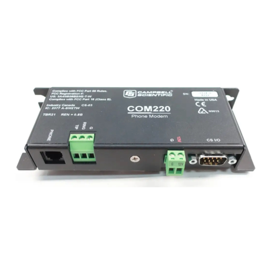
Class A Computing Devices......D-1 E. IC Information ............E-1 List of Figures 1. COM220 DIP switches. Five screws and the outer cover must be removed for access to the DIP switches..........1 2. COM220 ....................2 3. CR1000 and COM220 using remote telephone line ........4 4. -
Page 7: Introduction
(SDC) and modem enable (ME) communication, as well as various ME baud rates (9600 to 115200). The default settings for the COM220 at shipping are SDC7, and PakBus ready (see Appendix A for details). IMPORTANT The default settings ARE NOT compatible with dataloggers that have non-PakBus operating systems (e.g., CR510,... -
Page 8: Computer Requirements
Scientific dataloggers (except the CR200 series). This is not an RS-232 connection. Appendix B describes the CS I/O interface. The COM220 can be used as an originate modem at the datalogger site. For newer Pakbus dataloggers (e.g., CR800, CR1000, CR3000) use the ModemCallback instruction or the DialSequence and DialModem instructions to program the datalogger to originate a call to the computer. -
Page 9: Specifications
Weight: 0.16 kg (0.35 lbs) 3. Installation The COM220 is designed to be used with standard analog telephone lines. It will not work with a digital telephone line. Connection to telephone-company- provided coin service (central office implemented systems) is prohibited. - Page 10 Tx Rx Tx Rx CS I/O PERIPHERAL PORT MADE IN USA SC12 Cable Blue = Ring Burial Phone Cable Earth Ground Blue/White = Tip Phone Line Transient Protector (Model 6362 or 2372-01) FIGURE 3. CR1000 and COM220 using remote telephone line...
-
Page 11: Connecting To Earth Ground
3.2 Connecting to Earth Ground Connect the green 14 awg grounding wire (provided with the COM220) to the ground terminal (GND) on the COM220 and to the enclosure’s earth ground connection. If the site does not have a grounded enclosure, then connect the ground wire directly to an earth ground connection. -
Page 12: Telephone To Md485 Or Telephone To Rf Systems
When using a PakBus network with a datalogger configured as a router, the COM220 can be set for SDC7 and the radio for SDC8, or vice versa. Contact a Campbell Scientific Applications Engineer for more information. - Page 13 COM220 Telephone Modem Phone wires are live, typically with low voltage (24 Vdc). CAUTION While not harmful in most situations, Campbell Scientific recommends installing the surge protector in dry weather only by technicians with a healthy heart. FIGURE 5. Top view of surge suppressor wiring...
-
Page 14: Modem Settings
FIGURE 6. Side view of surge suppressor wiring 4. Modem Settings The COM220 is shipped from the factory with default settings that support PakBus dataloggers (e.g., CR800, CR1000, CR3000, CR10XPB). The modem comes configured for Synchronous Device Communication (SDC7), and if using a PakBus datalogger, can answer a call as soon as a call is detected. -
Page 15: Troubleshooting
Instructions for setting the COM220’s ME baud rate are found in Appendix A.1. 4) If the COM220 is set for Modem Enable (DIP switch 1 open) and you are unable to connect to the datalogger, try setting the datalogger BaudrateME to a negative number (e.g. - Page 16 MD485, the RF401, the SC932A, and the PDA-to-CS I/O connector. 7) If the COM220 is in SDC mode (the default is SDC7, with DIP switch 1 closed and DIP switch 2 open), verify that any other SDC devices attached to the datalogger are using a different SDC address (e.g., if the COM220...
- Page 17 COM220 Telephone Modem To comply with FCC rules and regulations, all repairs on the COM220 modem must be performed by Campbell Scientific, Inc. or an authorized agent of Campbell Scientific, Inc. For assistance in installation, troubleshooting, or for repair, contact Campbell Scientific: Campbell Scientific, Inc.
- Page 18 COM220 Telephone Modem...
-
Page 19: Changing Com220 Settings
1 must be open (i.e., Modem Enable mode selected). DIP Switches 3 and 4: ME Baud-rates DIP switches 3 and 4 only have effect when the COM220 is in Modem Enable mode. If the COM220 is in ME mode, switches 3 and 4 select the baud-rate... -
Page 20: Hayes At Commands
SC532 or SC532A device. An SC12 cable must be connected to the peripheral port on the SC532 or SC532A and the CS I/O port on the COM220. Another cable should connect the “RS232” port (if using an SC532 device) or the “PC”... - Page 21 SC532(A) or SC532 to the CS I/O port on the modem with a SC12 cable. If using a SC532, you will also have to apply 12V to the COM220 via a green connector attached to a power supply. If using an SC532A...
- Page 22 7) Follow the instructions that appear in the terminal emulator screen (Figure A-3). 8) Be sure to save all new commands before exiting (by entering 5 and enter). 9) When finished, return DIP switch 8 on the COM220 to its open position. FIGURE A-2. Device Configuration screen...
- Page 23 Appendix A. Changing COM220 Settings FIGURE A-3. Terminal Emulator screen in Device Configuration HAYES AT COMMAND SUMMARY: This manual does not attempt to be a primer on the Hayes AT command set. The commands are, therefore, only summarized below. For most applications, these commands will not need to be used.
-
Page 24: Downloading A New Operating System To The Com220
SC12 cable. If using an SC532, you will also have to apply 12 V to the COM220 via a green connector attached to a power supply. If using an SC532A device, power will be provided to the modem... -
Page 25: Program Examples
Appendix A. Changing COM220 Settings FIGURE A-4. Send OS Screen in Device Configuration A.4 Program Examples A.4.1 ModemCallback Example (for CR1000) The ModemCallBack instruction is available in the CR1000 with operating system std.12 or greater, in the CR3000 with operating system std.05 or greater and CR800 or CR850 with operating system std.03 or greater. -
Page 26: Dialmodem Example (For Cr1000
End Program A.4.2 DialModem Example (for CR1000) The program below does 2-minute callbacks via the COM220 configured for SDC7. DialModem is set equal to a variable, so that the success/failure result can be used by the EndDialSequence instruction. If the call fails, the link will be terminated at the EndDialSequence instruction. -
Page 27: P97 Instruction (For Cr10X
“20” CONNECT7200 “21” CONNECT12000 “25” CONNECT14400 Hence, to work with the COM220, the user must put in a NULL string, else the DialModem will fail unless by chance it returns the specific string the user entered. Therefore, it is highly recommended to use the “” string for the connect... - Page 28 In the example below, the program does two minute data callbacks via the COM220 phone modem. Edit instruction 13 with your PC’s (LoggerNet’s) phone number. Remember to set switch 1 open for Modem Enable mode, and switches 3 and 4 open for 9600 baud.
-
Page 29: Example Programs For Data-Callbacks Via A Cr1000 Datalogger Router
A.4.4 Example Programs for Data-Callbacks via a CR1000 Datalogger Router. In order to do data callbacks via a datalogger router with COM220 and RF401s or MD485s, they must all be configured to communicate with one another. In addition, two programs are necessary: one for the datalogger router and one for the remote datalogger. - Page 30 DialSequence (4094) StaticRoute(ComSDC8,4094,4094) ' So router discovers LoggerNet server DialSuccess = DialModem (ComSDC8,9600,"5551212","") ‘ Param 4 = "" allows CR1000 to accept all possible COM220 responses ‘ DialSuccess: -1 means successful, 0 means failure. EndDialSequence (DialSuccess) BeginProg Scan (2,Sec,0,0) PanelTemp (PanelTemperature,250)
-
Page 31: Cs I/O Connection
2. (input) Ground 3. (output) Ring - a logic high signifies a ring signal has been detected 4. (output) RX Data - serial data from COM220 5. (input) Modem Enable - a logic high internally switches power to the modem. A logic low internally shuts off power to the modem. -
Page 33: Theory Of Operation
The COM220 is supplied with 12 V from the datalogger’s CS I/O connector or from the COM220’s external power connector. The 12 V is then regulated to +5 V to give power to the ring detect circuitry. - Page 35 Appendix D. FCC Warning to Users of Class B Computing Devices WARNING This equipment generates, uses, and can radiate radio frequency energy, and if not installed and used in accordance with the instruction manual, may cause interference to radio communications. It has been tested and found to comply with the limits for a Class B computing device pursuant to Subpart J of Part 15...
-
Page 37: E. Ic Information
Appendix E. IC Information Industry Canada (IC) was formerly known as DOC. NOTE CP-01, Issue 8, Part I Section 14.1 “NOTICE: The Industry Canada label identifies certified equipment. This certification means that the equipment meets certain telecommunications network protective, operational and safety requirements as prescribed in the appropriate Terminal Equipment Technical Requirements document(s). - Page 40 Campbell Scientific Companies Campbell Scientific, Inc. (CSI) 815 West 1800 North Logan, Utah 84321 UNITED STATES www.campbellsci.com • info@campbellsci.com Campbell Scientific Africa Pty. Ltd. (CSAf) PO Box 2450 Somerset West 7129 SOUTH AFRICA www.csafrica.co.za • cleroux@csafrica.co.za Campbell Scientific Australia Pty. Ltd. (CSA)
Need help?
Do you have a question about the COM220 and is the answer not in the manual?
Questions and answers