Sign In
Upload
Download
Table of Contents
Contents
Add to my manuals
Delete from my manuals
Share
URL of this page:
HTML Link:
Bookmark this page
Add
Manual will be automatically added to "My Manuals"
Print this page
×
Bookmark added
×
Added to my manuals
Manuals
Brands
Pitney Bowes Manuals
Document Inserting Systems
DI380 Series
Service manual
Pitney Bowes DI380 Series Service Manual
Hide thumbs
1
2
Table Of Contents
3
4
5
6
7
8
9
10
11
12
13
14
15
16
17
18
19
20
21
22
23
24
25
26
27
28
29
30
31
32
33
34
35
36
37
38
39
40
41
42
43
44
45
46
47
48
49
50
51
52
53
54
55
56
57
58
59
60
61
62
63
64
65
66
67
68
69
70
71
72
73
74
75
76
77
78
79
80
81
82
83
84
85
86
87
88
89
90
91
92
93
94
95
96
97
98
99
100
101
102
103
104
105
106
107
108
109
110
111
112
113
114
115
116
117
118
119
120
121
122
page
of
122
Go
/
122
Contents
Table of Contents
Troubleshooting
Bookmarks
Table of Contents
Table of Contents
Introduction
Purpose
Equipment Covered
Related Publications
Contents
Safety Summary
Equipment Safety
Specifications
Material Specification
Machine Specification
Theory of Operation
Introduction to System Theory
Single Sheet Feeder Mode & Linked Feeder Mode
Flow Diagram- Single Sheet Feeder Mode
Insert Feeder Mode
Flow Diagram- Insert Feeder Mode
Two Sheet Feeder Mode
Flow Diagram- Two Sheet Feeder Mode
Single Sheet Feeder Plus an Insert Mode
Flow Diagram- Single Sheet Feeder Plus an Insert Mode
Two Sheet Feeders Plus an Insert Mode
Flow Diagram- Two Sheet Feeders Plus an Insert Mode
The Fold Only Mode
Flow Diagram- the Fold Only Mode
Accumulation from Main Sheet Feeder
Flow Diagram- Accumulation for Sheet Feeder 1 Mode
Double Detect Sensors
AC Motor
Removal & Replacement
Removing Covers and P.C.B
Removal of Jam Access Plate
Removing Sheetfeeder Separator Roller & PAD
Removing Carriage Assembly
Removal of Lower Collation Roller
Removal of Upper Insert Drive Rollers
FOLD Roller Removal/Replacement
Dismantling Insert Feeder (DI380/SI330 Only)
Dismantling Insert Feeder (DI425/SI3500 Only)
Removal of Top Assembly
Removal of Envelope Feed Rollers and Separator Pad (DI380/SI330 Only)
Removing Envelope Feeder (Di425/Si3500 ONLY)
Removing Envelope Feed Rollers & Separator Pad (DI425/SI3500 Only)
Removal of Flapper Assembly and Blade
Removal of the Transport Pivot Plate & Insertion Roller
Removal of Sealer Rollers
Removing the Inverter Motor Assembly
Removal of the Conveyor Transport Belts and Rollers
Removing Lower Flapper Rollers
Removal of the Lower Envelope Drive Roller
Removal of the Power Supply Unit and AC Motor
Adjustments
Envelope Feed Tray Guides (DI380/SI330 Only)
Envelope Feeder Offset Adjustment (DI425/SI3500 Only)
Envelope Separator Pad Side to Side Adjustment
Envelope Separator Pad Height (DI380/SI3300 Only)
Envelope Separator Pad Height (DI425/SI3500 Only)
Insertion Flipper Actuation Height/ Hold down Solenoid Adjustment
Insertion Hold down Finger Rest Position
Transport Pivot Plate End Float
Transport Pivot Plate Setting
Nesting Constant
Q Station Adjustments
Alignment
Q Station Calibration
Q Station Height
Insert Feeder Adjustments
Separator Roller Alignment
Separator Roller Height
Separator Pre-Feed Height (DI380/ SI330 Only)
Skew Adjustment
Flapper Adjustment
Omr
A Brief Overview of OMR on this System
OMR Specifications
Standard' OMR Positions Diagram
Offset' OMR Positions
Swis Offset' OMR Positions
OMR Mark Grouping
C' Fold and Double Fold Jobs
Z' Fold and Single Fold Jobs
Basic OMR
Benchmark
Safety
Boc-(Not) and Eoc-(Not)
Parity and Other Checks
Retime Marks
Allowable Mark Combinations
Enhanced OMR
Auto-Batch
Selective Insertion
Wrap-Around Sequence
Wrap Around Sequence Marks
Mark Code Interpretation
Enabling the OMR Features
Basic OMR
Enhanced OMR
Switching off OMR
Scanning Template
Procedure for Manually Setting the Sensitivity of the OMR Sensors
Service Menu & Troubleshooting
Entering the Service Menu
Parameters Menu
Final Assembly Number
Set Default Job
Set 50/60Hz
Serial Interface
View Error Codes
Set DDD
Set Service Counter
Set out of Material
Set Nesting Constant
Calibrate Q Station
Set Fold Plate Offsets
Set Env Stop Count
Set Serial Number
View Software Revision
Select OMR Basic Mode
Select OMR Enhanced
Basic Wetter Constant
OMR/ Acc Wetter Constant
T1 Clutch Release Time
T2 Envelope Hold Time
T3 Table Offset
OMR Offset Feeder
Clear Deck Delay
MMI Stack Limit
Service Diagnostics
Test Sensors
Test UART
Test D.C. Motors
Test Solenoids
Test A.C. Motor
Run Test Cycle
Test Display
Test Clutch and A.C Motor
Test OMR Sensors
Test Service Counter
Test Interlock Relay
Test DDD Calibration
Select Board Type
Test Memory
Troubleshooting Charts
General Information
Double Detect
Fault Finding Charts
Preventive Maintenance
General Information
The 100K Service
The 200K Service
Installation
Unpack and Check
Operator Training
Supervisor Training
Diagrams
Flow Diagrams
Component Locations
Switches, Sensors, Motors, Solenoids Test Levels
PCB Layout
Drive Belt Routing
Schematic - Insertion/Moistener/Exit Areas
Schematic- Sheet Feeders/ Collation Motor
Schematic- Fold Plates/ Half Fold
Schematic- Envelope Feeder/ AC Hand Crank (Manual Advance)
Schematic- P40 Envelope Platform Connector (DI425/SI3500)
Schematic- P41 Envelope Platform Motor Connector (DI425/SI3500)
Schematic- Insert Feeder
Schematic- Display/ PSU
Advertisement
Quick Links
Download this manual
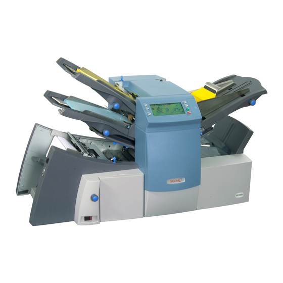
DI380/DI425 Series
Document Inserting Systems
(Includes Secap models SI3300/SI3500)
service Manual
FORM SDT333A (4-06)
Table of
Contents
Previous
Page
Next
Page
1
2
3
4
5
Advertisement
Table of Contents
Troubleshooting
service Menu & Troubleshooting
81
Select Board Type
89
Need help?
Do you have a question about the DI380 Series and is the answer not in the manual?
Ask a question
Questions and answers
Related Manuals for Pitney Bowes DI380 Series
Document Inserting Systems Pitney Bowes D1500 Operator's Manual
Pitney bowes inc. scanner user manual (118 pages)
Document Inserting Systems Pitney Bowes OfficeRight DI200 Operator's Manual
(49 pages)
Document Inserting Systems Pitney Bowes OFFICERIGHT DI200 Quick Install Manual
Pitney bowes inc. printer user manual (12 pages)
Document Inserting Systems Pitney Bowes OfficeRight DI380 Operator's Manual
(100 pages)
Document Inserting Systems Pitney Bowes DI380 OfficeRight Quick Reference Manual
Document inserting systems (21 pages)
Document Inserting Systems Pitney Bowes OfficeRight DI380 Operator's Manual
(76 pages)
Document Inserting Systems Pitney Bowes DI425 FastPac Quick Reference Manual
Document inserting systems (21 pages)
Document Inserting Systems Pitney Bowes DI500 Operator's Manual
(128 pages)
Document Inserting Systems Pitney Bowes DI500 Quick Reference Manual
(12 pages)
Document Inserting Systems Pitney Bowes FastPac DI900 Operator's Manual
(42 pages)
Document Inserting Systems Pitney Bowes FastPac DI900 Manuallines
Scan code guidelines (164 pages)
Document Inserting Systems Pitney Bowes FastPac DI950 Operator's Manual
(196 pages)
Document Inserting Systems Pitney Bowes FastPac DI900 Quick Start Manual
(19 pages)
Document Inserting Systems Pitney Bowes DI425 Series Service Manual
(122 pages)
Document Inserting Systems Pitney Bowes relay 2000 Operator's Manual
(92 pages)
Document Inserting Systems Pitney Bowes Epic Manual
Select inserting system (295 pages)
This manual is also suitable for:
Di425 series
Si3300
Si3500
Table of Contents
Save PDF
Print
Rename the bookmark
Delete bookmark?
Delete from my manuals?
Login
Sign In
OR
Sign in with Facebook
Sign in with Google
Upload manual
Upload from disk
Upload from URL


Need help?
Do you have a question about the DI380 Series and is the answer not in the manual?
Questions and answers