
Related Manuals for Pitney Bowes Epic


Summary of Contents for Pitney Bowes Epic
- Page 1 Shipping & Mailing Inserting Epic™ Select Inserting System Operator Guide US English Edition SV63276-RevA December 10, 2017...
- Page 2 ©2017 Pitney Bowes Inc. All rights reserved. This book may not be reproduced in whole or in part in any fashion or stored in a retrieval system of any type or transmitted by any means, electronically or mechanically, without the express written permission of Pitney Bowes. The use of this information by the recipient or others for purposes other than the training of customers on Pitney Bowes equipment may constitute an infringement of intellectual property rights of Pitney Bowes, and Pitney Bowes assumes no responsibility for any such use of the information. We have made every reasonable effort to ensure the accuracy and usefulness of this manual. However, we cannot assume responsibility for errors or omissions or liability for the misuse or misapplication of our products. Except as provided in writing, duly signed by an officer of Pitney Bowes, no license either express or implied, under any Pitney Bowes or third party’s patent, copyright or other intellectual property rights is granted by providing this information.
- Page 3 This guide is designed to support proper setup, operation, jam removal, troubleshooting, and basic maintenance activities associated with the Epic Select Inserting System. This guide covers Epic Select Inserter system components from the Buffer through the On Edge Stacker. System input content can be found in related operator guides. Version History Document Part Number Release Date Comments SV63276 RevA December 10, 2017 Initial release Related Documentation HPI Pinless Cutter (Y484/Y485) Operator Guide (OG-AF-INPU-102006) HPI Accumulator (Y470 ) Operator Guide (OG-ADFS-INPU-031005) HPI RAT/FIM (Y47EWP) Operator Guide (SV63088) Print+ Messenger Digital Inkjet System Operator Guide (OG_APF_PRINT_020111) Hunkeler UW6 Unwinding Module Operator Guide (OG-Hunk-Unwinder) Auto Buckle Chute (Y488, Y20R, Y20S) Operator Guide (OG-APF-INPU-011513) Pitney Bowes Epic Select Operator Guide December, 2017 Page iii of 6...
-
Page 4: Table Of Contents
About the Speed Indicators in DC About the DC Alarm Message Box Epic Select Inserting System Component Overview Indicator Lights 5 - Operator Adjustments About the Remote Control Operator Adjustments Adjusting the Envelope Feeder Separator Gap 52 3 - Power the System On and Off Adjusting the Envelope Fence Adjusting the Suction Cups in the Engine Power Up the System Adjusting the Engine Tongue Position Power Down the System Adjusting the Engine Throat Height About Engine Horns Changing Engine Horns 4 - Using Direct Connect Changing Envelope Settings Direct Connect Software Overview Setting Up the RAT (Right Angle Transfer) DC Main Screen Adjusting Amount of Sealer Fluid Applied Changing the UI Display Language Setting Up the Vertical Stacker Powering Down the DC Computer About the On Edge Stacker (OES) Pitney Bowes Epic Select Operator Guide December, 2017 Page iv of 6... - Page 5 Setting the Rotary Feeder Feed Deck Angle 131 8 - Error Recovery Adjusting the R otary Feeder Separator Pins 133 Using the W edge Accessory on the Rotary Error Recovery Feeder Alarms in Direct Connect Using the Jog Function on the Rotary Feeder 138 Removing Material Jams in the Buffer Insert Feeder Software Adjustments Removing Material Jams in the Friction Enabling and Disabling Feeders Feeder Document Information Removing Material Jams in the Rotary Setting Feeder Feed Modes Feeder Setting Backup Feeders (Backup Feed Removing Material Jams in the Engine Mode) Removing Material Jams in the Envelope Transport Envelope Setup (Xport Setup) Feeder Pitney Bowes Epic Select Operator Guide December, 2017 Page v of 6...
- Page 6 Removing Material Jams in the On Edge Environmental Operating Conditions Stacker Network and Power Requirements Removing M aterial Jams in the Flat Conveyor 215 Air Requirements 9 - Troubleshooting Troubleshooting Engine Troubleshooting Chassis Troubleshooting Buffer Troubleshooting 10 - Maintenance Operator Maintenance Replacing Suction Cups in the Engine Buffer Maintenance Rotary Feeder Maintenance Friction Feeder Maintenance Vertical Stacker Maintenance On Edge Stacker Maintenance 11 - Specifications Epic Select Engine (ZVE2) Envelope Specifications MPS/Epic Friction Feeder (Y554) Epic Rotary Feeder (Y558) Epic Buffer with TNT (Y574) Epic Turnover (Y371) Pitney Bowes Epic Select Operator Guide December, 2017 Page vi of 6...
-
Page 7: 1 - Safety
1 - Safety In this section Safety Information Power Operation Maintenance Warning Labels and Cautions Safety Features... -
Page 8: Safety Information
(LOTO) Program and Procedures Guide (PG-APFS-INSR-080609) Battery Handling (California Customers Only) The battery used in this product contains perchlorate material. California requires perchlorate containing products to be accompanied by the following notice: Perchlorate Material - special handling may apply. For more information refer to the following website: https://www.dtsc.ca.gov/hazardouswaste/perchlorate/. Ear Protection/Noise Exposure Guidelines Ear protection is required if noise exposure exceeds OSHA standards. There are many factors to be taken into consideration in each individual work area when dealing with ear protection. Factors such as floor noise, length of exposure to noise, loss of hearing history in individual employees can all play a role in requirements. Analyze your specific work area environment to ensure safe practices. These are standard OSHA guidelines. 85dBA time weighted average over an 8-hour shift requires hearing protection be made available to employees and use is recommended. (European Union standard is 80dBA) 90dBA time weighted average over an 8-hour shift mandates hearing protection is used. (European Union standard is 85dBA) Note: Local jurisdictions may have more stringent requirements. Refer to local regulations for standards and requirements in your area. Pitney Bowes Epic Select Operator Guide December, 2017 Page 2 of 288... -
Page 9: Power
System Power The inserter receives its power from a customer provided, single drop, external connection. General Power Safety Use the power cord supplied with the machine chassis at the power entry and plug it into a properly grounded (earthed) and easily accessible wall outlet located near the machine. Failure to properly ground (earth) the machine can result in severe personal injury and/or fire. The power cord wall plug is the primary means of disconnecting the machine from the AC power supply for Lock Out/Tag Out (LOTO). Do not use an adapter plug on the line cord or wall outlet. Do not route the power cord over sharp edges or trap it between furniture. Ensure there is no strain on the power cord where it becomes jammed between the equipment, walls or furniture. Be certain the area in front of the wall receptacle into which the machine is plugged is free from obstruction. For input and output modules - power is distributed from the chassis. Use the AC connectors supplied with the modules to connect to system power. Do not connect external devices to the inserter. Pitney Bowes Epic Select Operator Guide December, 2017 Page 3 of 288... -
Page 10: Operation
Before starting the machine, check that: All persons are clear of the machine No maintenance work is being performed on the machine All covers and guards are in place The machine is free of scraps, jams, and foreign objects Never run the machine when any of the covers or guards are missing. Keep loose clothing, jewelry, long hair and neckties away from all moving parts. Make sure that clothing and hair fit closely to your body and remove all jewelry. When lifting covers, wait for all parts to stop moving before placing hands near paper path. Avoid touching moving parts or materials while the machine is in use. Before clearing a jam, be sure machine mechanisms come to a stop. When removing jammed material, avoid using too much force to prevent personal injury and damaging equipment. The machine will only be serviced by trained and authorized personnel. The main power source may need to be disconnected before servicing, depending on the type of service activity. It is essential that personnel employ safe working practices and observe all related regulations and legal requirements for safety when operating this product. Pitney Bowes Epic Select Operator Guide December, 2017 Page 4 of 288... -
Page 11: Maintenance
Use only Pitney Bowes approved printer ink and cleaners. To prevent overheating, do not cover the vent openings. Do not store flammable fluids inside this machine. Do not place any container with liquid on this machine, (i.e. coffee cups, soda, etc.) Do not use flammable cleaners in this machine. Do not use aerosol air canisters. It is recommended that a vacuum cleaner be used to remove dust and debris from the machine paper path. If you have to use shop air, t urn the system off before you begin cleaning. Verify the shop air does not contain excessive oil or water. Do not spray liquid onto or into any part of the machine. Use a cloth to apply cleaning solution. Pitney Bowes Epic Select Operator Guide December, 2017 Page 5 of 288... -
Page 12: Warning Labels And Cautions
Safety Warning Labels and Cautions Pitney Bowes declines all liability in the event of material damage or bodily injury resulting from negligence in the application of these precautions i n respect to handling, operating, or servicing, even if not expressly stated in these instructions. Caution: Pinch Point Rotating Shaft Pinch hazard; rotating shaft. Keep hands clear during operation. Caution: Pinch Point Rollers Pinch hazard; moving belts and rollers in this area. D o not operate with cover open. Caution: Hand Entanglement Moving belts; use caution. Keep hands clear during operation. Caution: Rotating Roller Hazard Moving rollers; use caution. Keep hands clear of this area during operation. Pitney Bowes Epic Select Operator Guide December, 2017 Page 6 of 288... - Page 13 Safety Caution: Hand Crush from Left Crush hazard; force from the left. Use caution; keep hands clear during operation. Caution: Hand Crush from Above Crush hazard; force from above. Use caution; keep hands clear during operation. Caution: Hand Crush Crush hazard; use caution when working in this area. Caution: Hot Surface Burn hazard; hot surface inside. Allow to cool before servicing. Caution: Motor Capacitor Discharge Allow six minutes for motor capacitors to discharge before servicing motor driver module. Pitney Bowes Epic Select Operator Guide December, 2017 Page 7 of 288...
- Page 14 Safety Warning! Severe Shock Hazard Only authorized personnel should service this equipment. Turn power OFF before entry. Caution: Hand Abrasion Caution, moving belts. Keep hands clear during operation to avoid hand abrasion. Caution: Hair Entanglement Caution, rotating parts. Keep hair, jewelry, and loose clothing away during operation to prevent potential injury. Caution: Cut Hazard Caution, sharp blades. Keep hands clear during operation. Caution: Sharp Point Caution, sharp points. Use care when working in this area; keep hands clear during operation. Pitney Bowes Epic Select Operator Guide December, 2017 Page 8 of 288...
- Page 15 Safety Caution: Tip Over Hazard When moving unit, push or pull in direction shown by arrow. Tipping over may cause injury or damage to equipment. Caution: Refer to Operator Guide Read and understand operator information before using this machine. Failure to follow operator instruction could result in serious injury. Additional Feeder Safety Risks Although every effort has been made to reduce the hazards to a minimum, some residual risk remains. The feed station is open to allow for paper loading onto the feed hopper belts. A lthough these belts travel very slowly, always be aware of the moving belts and use proper caution in this area. Caution: Entanglement in Feeder Belts Feeder belts are moving when material is transported. K eep loose clothing, jewelry and hair away during operation to prevent potential injury. Caution: Pinch Point - Infeed Envelope Conveyor Gripper To prevent potential injury do not put your hands near the infeed envelope conveyor gripper area. Pitney Bowes Epic Select Operator Guide December, 2017 Page 9 of 288...
-
Page 16: Safety Features
ESTOP switch to activate it. Turn the red knob c lockwise to deactivate it. I f the ESTOP switch is pressed while the machine is running, the entire machine will come to an immediate stop. When the ESTOP is activated, the m ain DC screen will indicate this, as well as which location on the machine the ESTOP was engaged. Only use ESTOPs for emergency situations with the potential of causing injury or machine damage. ESTOP Switch (red) There is an ESTOP icon on the Direct Connect main screen that indicates there is an ESTOP or interlock open, prohibiting the machine from starting. ESTOP Icon - Main DC Screen (red) Pitney Bowes Epic Select Operator Guide December, 2017 Page 10 of 288... - Page 17 B reaking the interlock safety connection should never be used as an emergency stop option. The covers should not be opened while the machine is running. If an interlock cover is accidentally opened while the inserter is running, the connection is broken (via the latch magnet) and the system will immediately stop in the interlock area, while bringing the rest of the system to a controlled stop. The inserter will not start until that cover is closed and the interlock safety connection is satisfied. Every operator accessible cover on the inserter that exposes an operator to a potential hazard while the machine is running is equipped with an interlock cover. Note: Covers that require a tool for access are to be opened by trained Service personnel only. If the cover is partially closed, the icon on the main DC screen will not change color or indicate an open cover, but the machine will not start. If this occurs, verify the cover is fully closed. Pitney Bowes Epic Select Operator Guide December, 2017 Page 11 of 288...
- Page 18 Safety Insert Rotary Feeder Interlock Switch Each rotary feeder has one gray interlock switch that can be used to disable the rotary feeder locally. In this case, the feeder is disabled, with no power. The inserter system still has power but is not able to run when the feder interlock switch is engaged. Insert Rotary Feeder Interlock Switch (gray) Pitney Bowes Epic Select Operator Guide December, 2017 Page 12 of 288...
- Page 19 2 - Product Overview In this section Epic Select Inserting System Component Overview Indicator Lights About the Remote Control...
-
Page 20: Epic Select Inserting System
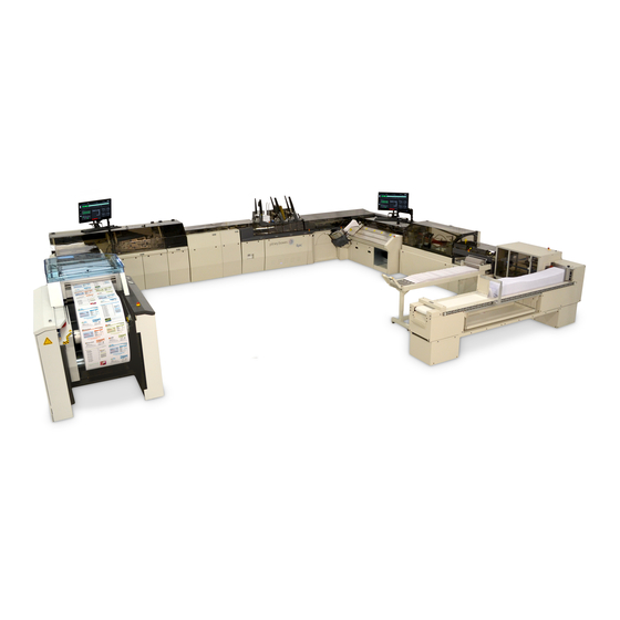
Product Overview Epic Select Inserting System The Epic Select Inserting System is capable of processing up to 21,000 transactional mailpieces per hour, depending on the application and configurations of the inserter. The system process tri-fold/C-fold and half folds material and is controlled by Direct Connect (DC) software. Epic Select Inserting System Pitney Bowes Epic Select Operator Guide December, 2017 Page 14 of 288... - Page 21 Width 5.5-inch (140 mm) 11-inch (279.4 mm) Paper Width 16 lb bond (60gm/sq m) 28 lb bond (100 gm/sq.m) Paper Weight 6 lbs/linear inches Document Dimensions (when supplied from the input) Minimum Maximum Depth 3.5-inch (89 mm) 6.25-inch (158 mm) Width 7-inch (177 mm) 11-inch (279.4 mm) Paper Weight 18 lb bond (70gm/sq. m) 28 lb bond (100 gm/sq.m) Perforation Strength 6 lbs linear inches Pitney Bowes Epic Select Operator Guide December, 2017 Page 15 of 288...
- Page 22 Material should be stored within a temperature range of 65 - 85° Material should be stored within a range of 40% - 60% relative humidity Paper Curl These paper curl guidelines apply to 8.5" width paper. Curl Direction Toward Image Away from Image Short Direction* Under 10 mm Under 5 mm Long Direction** Under 20 mm Under 15 mm NOTE: Diagonal Curl is considered unacceptable. * Short Direction Curl: short edges of the sheet curl ** Long Direction Curl: long edges of the sheet curl Options The Epic Select Inserter can be configured with these options: Part # Flats / Folded Rotary Feeder Y558 Friction Feeder Y554 Pitney Bowes Epic Select Operator Guide December, 2017 Page 16 of 288...
-
Page 23: Component Overview
Product Overview Component Overview The Epic Select Inserting System consists of these main modules and sections. Item Description Item Description Input modules Sealer Buffer Turnover Chassis Print+ Messenger Printer (optional) Insert Feeders Vertical Stacker (with flats stacker) Engine On Edge Stacker Envelope Feeder Epic Select System Pitney Bowes Epic Select Operator Guide December, 2017 Page 17 of 288... - Page 24 Insert Feeders - T his is where the inserts are added to the collation based on the mode configuration. Both friction and rotary style feeders can be intermixed. Envelope Feeder - Envelopes are staged in this module and f ed into the engine as needed. Engine - This is where the envelope flap is opened and the collation is inserted into the envelope. After insertion, the envelope (with collation inside) is transported to the sealer. There are both manual and automated adjustments in the engine. Sealer - This is where the envelope flap is moistened and closed to seal the envelope. The sealer module has a built-in Vertical Stacker (VS1). Turnover - This is used when the application requires postage to be printed on the envelope. The turnover turns the envelope from face down to face up, allowing you to print on the front of the envelope. Vertical Stackers - These stackers divert and stack good and bad mailpieces, based on application or system error. A stacker for flats can be installed under a vertical stacker, a nd is operator removable. On Edge Stacker - This is where the finished mailpieces are stacked vertically, until they are removed and placed in mail trays. Pitney Bowes Epic Select Operator Guide December, 2017 Page 18 of 288...
-
Page 25: Indicator Lights
Product Overview Indicator Lights System indicator lights are located in various areas on the inserter. When an error occurs or operator intervention is needed, the indicator light will illuminate to a bright yellow (steady on or flashing) to help direct an operator to the appropriate area of the machine. Indicator lights also alert operators when there is an open cover or ESTOP activated and when the material in the insert feeder gets low. System Indicator Lights LED State Meaning Ready to run Slow blink Feeder material low Fast blink Interlock open System Indicator Lights Pitney Bowes Epic Select Operator Guide December, 2017 Page 19 of 288... -
Page 26: About The Remote Control
Product Overview About the Remote Control Direct Connect (DC) software is the operating system software that controls the inserter. You make selections in DC using a mouse, keyboard, and computer monitor for setting up, running, and servicing the inserter. A touch screen monitor is optional. Although DC is used to control many aspects of the inserter, the remote control unit should be used as much as possible to operate the system. Remote Control Functions Start and Stop - Press the Start and Stop buttons to start and stop the machine. Cycle- If the input is in Service mode and running, press the Cycle button to feed one sheet at a time. Clear Deck - To clear the deck ( an operating sequence that clears the inserter deck of all mailpieces) press the Stop and Cycle buttons at the same time. Refer to the Clear Deck Function topic for more information. Pitney Bowes Epic Select Operator Guide December, 2017 Page 20 of 288... -
Page 27: 3 - Power The System On And Off
3 - Power the System On and Off In this section Power Up the System Power Down the System... -
Page 28: Power Up The System
Power the System On and Off Power Up the System There are specific instructions for powering up the system, both the inserter and the Direct Connect computer. Power Up the Inserter 1. Locate the main power switch (on the lower chassis cover left of the first feeder, closest to the input) and lift it up, to the ON position. Main Power Switch Pitney Bowes Epic Select Operator Guide December, 2017 Page 22 of 288... - Page 29 Power the System On and Off Power Up the Direct Connect Computer 1. When the DC computer completely boots up, at the Begin Login window hold down the [CTRL] and [ALT] keys at the same time and press the [Delete] key. The Login window opens. 2. To log into Windows, if the system is connected to a network, enter the system password. If it is not connected to a network, click OK. Note: Depending on your site, the Windows log in may be automatic and you will not be prompted to perform this step. 3. Log in to DC. Pitney Bowes Epic Select Operator Guide December, 2017 Page 23 of 288...
-
Page 30: Power Down The System
Power the System On and Off Power Down the System When you power down the system, you cannot simply turn off the power. There are specific instructions for powering down the system, both the inserter and the Direct Connect computer. Power Down the Direct Connect Computer 1. Clear all the material in the paper path. 2. Click Control > Power Down on the DC main menu bar. 3. When the Power Down window opens, click Yes. This powers down the DC computer. Pitney Bowes Epic Select Operator Guide December, 2017 Page 24 of 288... - Page 31 Power the System On and Off Power Down the Inserter After you log out of DC, the message: It is now safe to turn off your computers displays. Note: After you power down the DC computer, wait about 30 seconds before proceeding; this gives time for other computers in the system to shut down safely. 1. Locate the main power switch on the system (on the lower chassis cover left of the first feeder, closest to the input) and pull it down to the OFF position. Main Power Switch Pitney Bowes Epic Select Operator Guide December, 2017 Page 25 of 288...
- Page 32 This page intentionally left blank.
- Page 33 4 - Using Direct Connect In this section Direct Connect Software Overview DC Main Screen Changing the UI Display Language Powering Down the DC Computer Viewing DC Software Details Logging In and Logging Out of DC Loading a Mode Setting the Mail Date Checking Status with Job Manager Accessing Reports in DC Starting and Stopping the Inserter Using DC Assigning an MRDF File (File Based Jobs) Disabling (and Enabling) the Inserter Clear Deck Function About the Speed Indicators in DC About the DC Alarm Message Box...
-
Page 34: Direct Connect Software Overview
The inserting process is assembling mailpieces by feeding documents, envelopes and inserts into an inserter, and starting the machine so that it assembles the mailpiece. There are two main inserting processes - including direct scanning and file based scanning. Direct Scanning Direct scanning is when DC uses a barcode to control the inserter and provide real-time decision-making about mail processing. A document w ith a barcode (for example, a monthly statement) is fed into the inserter. DC reads and decodes the barcode, and the information is used to control the inserting process for the mailpieces. File Based Scanning Fle based scanning is when DC uses an Input file (also known as the MRDF or mail run data file) to control the inserter and provide real-time decision-making about mail processing. A document with a barcode (for example, a monthly statement) is fed into the inserter. DC reads and decodes the barcode, and the information is used to grab the instructions from the Input file for putting the mailpiece together. The Input file can store an unlimited number of instructions for assembling a mailpiece. File based scanning with DC connects to a network and file server to communicate and store the Input file for the inserting process. Because the Input file is stored on a central server, it can be accessed by all of the inserters. This allows a mailing job to be run on any inserter or split among inserters. Pitney Bowes Epic Select Operator Guide December, 2017 Page 28 of 288... -
Page 35: Dc Main Screen
Using Direct Connect DC Main Screen The DC main screen c onsists of machine operation buttons, icons, and animated objects designed to match components on your actual machine. You can control certain operations of the system and software through this screen. Note: Graphics, settings, data, and modes shown here are for reference only and may not match the custom mode settings, object icons, machine elements or data used for the inserter system in your facility. Pitney Bowes Epic Select Operator Guide December, 2017 Page 29 of 288... - Page 36 Using Direct Connect The main screen contains the following major areas. Item Description Banner Bar Main Menu Bar Menu Buttons Icons Start Bar Alarm Icon Alarm Message Box Inserter Model Pitney Bowes Epic Select Operator Guide December, 2017 Page 30 of 288...
- Page 37 Using Direct Connect Main Menu Bar At the operator level, the main menu bar gives operators access to power up/down the system, change the display language and get details about the software. Control - select Control to power down the system or change the language displayed on the screen. About - select About to access s oftware information that includes version, copyright date, library name, installation date, and system identification number. Pitney Bowes Epic Select Operator Guide December, 2017 Page 31 of 288...
-
Page 38: Changing The Ui Display Language
Using Direct Connect Changing the UI Display Language When you are logged in as an Operator, you can change the UI display language from the main menu bar on the main DC screen. 1. Click Control on the DC main menu bar. 2. Hover over Switch Languages and select the language you want. Note: The UI display language is typically set by Service during the installation process. Pitney Bowes Epic Select Operator Guide December, 2017 Page 32 of 288... -
Page 39: Powering Down The Dc Computer
Using Direct Connect Powering Down the DC Computer When you are logged in as an Operator, you can power d own the DC computer from the main menu bar on the main DC screen. 1. Click Control on the DC main menu bar. 2. Select Power Down and click Yes when prompted. This shuts down the DC computer. Note: If you are logged in as an Operator, you cannot exit DC, you can only power down the DC computer. Pitney Bowes Epic Select Operator Guide December, 2017 Page 33 of 288... -
Page 40: Viewing Dc Software Details
Using Direct Connect Viewing DC Software Details When you are logged in as an Operator, you can view details about the DC software from the main menu bar on the main DC screen. 1. Click About! on the main menu bar in DC, a dialog opens with software details (version, install date, ID number). 2. Click Close to exit. Pitney Bowes Epic Select Operator Guide December, 2017 Page 34 of 288... -
Page 41: Logging In And Logging Out Of Dc
There are a few different login levels in DC. O ptions and features you see or have access to vary depending on your user access level - Operator, Key Operator, Manager, Service, Administrator and Engineer. Logging In 1. Click the Login button on the main DC screen. 2. Select Login from the drop-down menu. 3. When the User Login dialog opens, double-click Operator (or your login name). 4. When prompted, enter your password and click OK. Logging Out 1. Click the Login button o n the main DC screen. 2. Select Logout from the drop-down menu. Note: When no one is logged in, the Login button shows a locked padlock icon. When a user is logged in, the Login button shows an unlocked padlock icon and the operator's name is displayed in the banner area of the screen. Pitney Bowes Epic Select Operator Guide December, 2017 Page 35 of 288... - Page 42 Change UI display language Power down the DC computer View DC software details Load a mode Set the mail date Check status with Job Manager Access standard report Start and stop the inserter Assign an MRDF file Enable and disable inserter components Clear the deck Monitor speed indicators View and access alarm screens View Help dialogs Note: Key Operators have the same access operators do, and they can get to some additional setup screens. Pitney Bowes Epic Select Operator Guide December, 2017 Page 36 of 288...
-
Page 43: Loading A Mode
Using Direct Connect Loading a Mode DC uses operating modes to run applications on the inserter. A mode contains the unique combination of system settings for processing a specific job. Some setting examples include timing parameters, file locations, scan code layout, forms length, and the icons displayed on the main DC screen. Note: In order to see available modes you must be logged in to DC. Typically, operators load modes, they do not create them. Loading a Mode Before you run a job, load the mode. 1. Log in to DC. 2. Click the Mode button on the main DC screen. 3. Select Load Mode from the drop-down menu. Pitney Bowes Epic Select Operator Guide December, 2017 Page 37 of 288... - Page 44 Using Direct Connect 4. Highlight the mode for the job you are setting up and click OK. Note: After you load the mode successfully, the mode name appears in the banner area at the top of the main DC screen. Pitney Bowes Epic Select Operator Guide December, 2017 Page 38 of 288...
-
Page 45: Setting The Mail Date
Using Direct Connect Setting the Mail Date If you are logged in as an Operator, you can set the mail date for the job, before you run it. 1. Click the JobMgr button on the main DC screen. 2. Select Set Mail Date from the drop-down menu. 3. When the dialog opens, type in the mail date. (It must be today's date or a date in the future.) 4. Click OK. Pitney Bowes Epic Select Operator Guide December, 2017 Page 39 of 288... -
Page 46: Checking Status With Job Manager
Using Direct Connect Checking Status with Job Manager If you are logged in as an Operator, you can check job status information about the inserter you are working on, the current job, the operator, etc. 1. Click the JobMgr button on the main DC screen. 2. Select Status from the drop-down menu. A Job Manager Status dialog opens and displays information about the machine, the current job, the operator, etc. 3. Click Close to exit. Pitney Bowes Epic Select Operator Guide December, 2017 Page 40 of 288... -
Page 47: Accessing Reports In Dc
Using Direct Connect Accessing Reports in DC When you are logged in as an Operator, you can access a standard machine status report, which you can view, save or print. 1. Click the Reports button on the main DC screen. 2. Select Reports > Report from the drop-down menu. 3. When the dialog opens, you can click Print, Save or Close to exit. Accessing Saved Reports Feature To view the reports you may have previously saved: 1. Click the Reports button the main DC screen. 2. Select Reports > View Saved Reports from the drop-down menus. 3. When the folder opens, b rowse through the reports you saved and double-click the desired report to view details. Note: The Direct Reports option is not available at an Operator log in access level. Pitney Bowes Epic Select Operator Guide December, 2017 Page 41 of 288... -
Page 48: Starting And Stopping The Inserter Using Dc
Using Direct Connect Starting and Stopping the Inserter Using DC When you are logged in as an Operator, you can start and stop the inserter using the buttons in the Start bar area on the bottom of the main DC screen. Start Button When you click the Start button, the inserter starts running and the Menu, Start, and Cycle buttons are replaced by the Stop button. Stop Button When you click the Stop button, the system stops at a predetermined state, to ensure all the mailpieces in process are controlled; this helps to avoid errors or jams. Also, when you click Stop, the Menu, Start, and Cycle buttons display again. Note: You can also start or stop the inserter using the remote control. Pitney Bowes Epic Select Operator Guide December, 2017 Page 42 of 288... -
Page 49: Assigning An Mrdf File (File Based Jobs)
Using Direct Connect Assigning an MRDF File (File Based Jobs) If you are running a file based job, you need to assign an MRDF file to the job. The MRDF is a data file that contains a set of information used for processing the mail (i.e. number of pages, number of collations, etc.). If this is not a file based job, you can skip this step. 1. Click on the Menu button on the bottom of the main DC screen, near the Start bar. 2. Select Open File or Start Job from the drop-down menu. 3. In the Select Mailrun field, type in the name of the MRDF file or scan it from the work order. 4. When the file name populates the field, click OK to open it. Pitney Bowes Epic Select Operator Guide December, 2017 Page 43 of 288... -
Page 50: Disabling (And Enabling) The Inserter
Using Direct Connect Disabling (and Enabling) the Inserter When you are logged in as an Operator, you can disable the inserter from any run activity. Typically, you might only disable the system if directed by Service. For example, if Service needs to perform diagnostic activity on the machine, they may ask you to disable the system, to avoid having to completely shut down. This freezes system activity, preserving data that may be helpful for diagnosing issues. When you are ready to start running the job again, you can enable the system. 1. Click the Menu button on the bottom of the main DC screen, near the Start bar at the bottom of the screen. 2. Select Disable System. The inserter stops and cannot be started until it's enabled through DC. 3. When you are ready to run the inserter, click the Menu button and select Enable System. The inserter is enable to start when you are ready. Pitney Bowes Epic Select Operator Guide December, 2017 Page 44 of 288... -
Page 51: Clear Deck Function
When you are logged in as an Operator, you can initiate clear deck . There are three ways to do this: Click the Menu button on the main DC screen and select Clear Deck from the m enu. Press and hold the [Cycle] button on the remote control (wait for abut 1 second), and then press the Stop button while still holding down the Cycle button. Click the Chassis object on the main DC screen and select Clear Deck from the menu. Once initiated, the Clear Deck indicator flashes at the bottom of the screen. What Happens When Clear Deck is Initiated If the machine is running when Clear Deck is initiated, all the material in the paper path will be processed and cleared from the machine. If the machine is not running when Clear Deck is initiated, the next time the machine is started, all mail that was being processed is completed and then the system will stop. Pitney Bowes Epic Select Operator Guide December, 2017 Page 45 of 288... - Page 52 Using Direct Connect Once initiated, the Clear Deck message flashes at the bottom of the screen. Pitney Bowes Epic Select Operator Guide December, 2017 Page 46 of 288...
-
Page 53: About The Speed Indicators In Dc
Using Direct Connect About the Speed Indicators in DC The speed indicators are located on either side of the Start bar on the bottom of the main DC screen. The input speed indicator displays the input speed (the speed in which pages are fed) in number of mailpieces per hour (shown as 0 below) as well as the total number of pages fed (shown as 63 here). The output speed indicator displays the output speed in numbers of mailpieces per hour (shown as 677 here), as well as the total number of mailpieces that reached the output stacker (shown as 12 here). Pitney Bowes Epic Select Operator Guide December, 2017 Page 47 of 288... -
Page 54: About The Dc Alarm Message Box
Using Direct Connect About the DC Alarm Message Box Alarms are reasons why the inserter stops. When the machine stops because of a problem, the alarm message box opens at the bottom of the DC main screen over the start bar. Alarm Message Box When an alarm displays in the alarm message box, you can get more information about what and where the issue is, and suggestions on how to solve it.. Refer to the Alarm Recovery topic for more detailed information on how to manage DC alarms. Pitney Bowes Epic Select Operator Guide December, 2017 Page 48 of 288... - Page 55 5 - Operator Adjustments In this section Operator Adjustments Adjusting the Envelope Feeder Separator Gap Adjusting the Envelope Fence Adjusting the Suction Cups in the Engine Adjusting the Engine Tongue Position Adjusting the Engine Throat Height About Engine Horns Changing Engine Horns Changing Envelope Settings Setting Up the RAT (Right Angle Transfer) Adjusting Amount of Sealer Fluid Applied Setting Up the Vertical Stacker About the On Edge Stacker (OES) Setting Up the Entrance to the On Edge Stacker Centering Mail on the On Edge Stacker Conveyor Belt 90 Adjusting t he Belt Speed and Stack Pressure on the On Edge Stacker Adjusting On Edge Stacker Fingers Adjusting the Engine Observation Side Guides Adjusting the Chassis Side Guides Adjusting the Buffer Chassis Side Guides Adjusting the Chassis Entrance Brush Height Adjusting Chassis Material Center Deck Control Straps Setting the Chassis Collation Length Setting the Chassis Speed Friction Feeder Mechanical Adjustments Adjusting the Friction Feeder Separator...
- Page 56 Operator Adjustments Adjusting the Friction Feeder Side Guides Adjusting the Feeder Pack Control Ramp Rotary Feeder Mechanical Adjustments Using Rotary Feeder Suction Cups Adjusting the Rotary Feeder Side Guide and Backstop Adjusting the Rotary Feeder Deck Position Setting the Rotary Feeder Feed Deck Angle Adjusting the R otary Feeder Separator Pins Using the W edge Accessory on the Rotary Feeder Using the Jog Function on the Rotary Feeder Insert Feeder Software Adjustments Enabling and Disabling Feeders Document Information Setting Feeder Feed Modes Setting Backup Feeders (Backup Feed Mode) Transport Envelope Setup (Xport Setup) Setting Separator Options for Friction Feeders Recalibrating the Double Detect Feature Pitney Bowes Epic Select Operator Guide December, 2017 Page 50 of 288...
-
Page 57: Operator Adjustments
Envelope Feeder Engine Sealer Vertical Stacker On Edge Stacker (OES) Chassis Friction Feeders (insert feeder) Rotary Feeders (insert feeder) Buffer Note: After loading a mode, home the chassis b y pressing the Start button once. Job Changeovers Changeover adjustments may be required if the new job you are about to run has material that is a different orientation (portrait or landscape), size or material thickness than the previous job. Some of the adjustments for a job changeover the system makes automatically, and some you need to make manually. Refer to the "Job Changeover Guidelines" topic for detailed information. Pitney Bowes Epic Select Operator Guide December, 2017 Page 51 of 288... -
Page 58: Adjusting The Envelope Feeder Separator Gap
Operator Adjustments Adjusting the Envelope Feeder Separator Gap The envelope feeder separator sets the gap, so only one envelope feeds at a time. The size of the gap is set based on envelope thickness. If the gap is too tight, envelopes will not feed. If the gap is open too wide, multiple envelopes will feed. 1. Pull the separator access lever towards you until it stops and hold it in place. Pull Back Separator Access Lever Pitney Bowes Epic Select Operator Guide December, 2017 Page 52 of 288... - Page 59 Separator Roller Area (roller not seen in photo) Separator Adjustment Knob Insert Envelope Between Separator Rollers 3. Release the access lever. 4. Turn the separator knob to adjust for thickness. Y ou should feel a very slight drag on the envelope as you try to remove it from the separator roller. (Adjust the separator knob only a few clicks and recheck the settings.) a. If there is too much drag on the envelope, open the knob to reduce drag. b. If there is not enough drag on the envelope, close the knob to increase drag. Pitney Bowes Epic Select Operator Guide December, 2017 Page 53 of 288...
- Page 60 Operator Adjustments 5. Remove the envelope. Note: This adjustment gets the feeder gap close to the final setting. During operation testing additional adjustments may be necessary if doubles or no envelopes are feeding. Pitney Bowes Epic Select Operator Guide December, 2017 Page 54 of 288...
-
Page 61: Adjusting The Envelope Fence
Operator Adjustments Adjusting the Envelope Fence The envelope fence supports the envelopes at the feed head and also keeps the envelopes aligned with the feed head. 1. Load a stack of envelopes (flap down and facing to the right) in the envelope hopper. 2. Loosen the lock down lever and slide the envelope fence up or down until the alignment arrow lines up with the top edge of the envelopes. Loosen Lever and Use Alignment Arrows 3. When the fence is properly positioned, lock it in place. Pitney Bowes Epic Select Operator Guide December, 2017 Page 55 of 288... -
Page 62: Adjusting The Suction Cups In The Engine
Adjusting the Suction Cups in the Engine The suction cups in the engine open up the throat of the envelope for insertion. They can be adjusted to accommodate different envelope throat sizes. 1. Lift the engine cover. 2. Lift the upper engine to access the vacuum deck. 3. Open the envelope and fold the flap inside, so the throat of the envelope is showing. 4. Align the top of the envelope (flap crease line) with the deck lines shown here. (This is where the envelope is staged. All adjustments should be made from this position.) Align Envelope Pitney Bowes Epic Select Operator Guide December, 2017 Page 56 of 288... - Page 63 Operator Adjustments 5. Close the upper engine. Close Upper Engine Envelope Aligned - view from above Pitney Bowes Epic Select Operator Guide December, 2017 Page 57 of 288...
- Page 64 Operator Adjustments 6. Use the operator setup tool to loosen the three suction cup lockdown screws. Suction Cup Lockdown Screws Pitney Bowes Epic Select Operator Guide December, 2017 Page 58 of 288...
- Page 65 Operator Adjustments 7. Slide the suction cup arm to position the suction cup approximately 1/8-inch (3 mm) from the envelope throat. (Do this for all three suction cups.) Item Description Envelope Flap Envelope Throat Suction Cups 1/8-inch (3 mm) space Position Suction Cups - 1/8-inch (3 mm) from throat 8. Tighten the suction cup lockdown screws. 9. Remove the envelope. 10. Lower the upper engine. 11. Close the cover. Pitney Bowes Epic Select Operator Guide December, 2017 Page 59 of 288...
-
Page 66: Adjusting The Engine Tongue Position
Adjusting the Engine Tongue Position The engine tongue helps guide the collation into the open envelope and prevents it from catching on the envelope throat. The tongue position needs to be adjusted when the throat of the envelope changes. To adjust the engine tongue position: 1. Lift the engine cover. 2. Lift the upper engine to access the vacuum deck. 3. Open the flap of the envelope and fold the flap inside, so the envelope throat is showing. 4. Align the top of the envelope (flap crease line) with the deck lines shown here. (This is where the envelope is staged. All adjustments should be made from this position.) Envelope Flap Against Insert Ledge Air Pitney Bowes Epic Select Operator Guide December, 2017 Page 60 of 288... - Page 67 Operator Adjustments 5. Close the upper engine. Close Upper Engine 6. Use the operator setup tool to loosen both horizontal tongue lockdown screws. Tongue Lockdown Screws Pitney Bowes Epic Select Operator Guide December, 2017 Page 61 of 288...
- Page 68 Operator Adjustments 7. Slide the tongue assembly so it is 1/8" (3 mm) from the edge of the envelope throat. Item Description Tongue Assembly Envelope Throat 1/8" (3 mm) gap between tongue and throat Position Tongue Assembly 8. Tighten the lockdown screws. 9. Remove the envelope. 10. Lower the upper engine. 11. Close the engine cover. Pitney Bowes Epic Select Operator Guide December, 2017 Page 62 of 288...
-
Page 69: Adjusting The Engine Throat Height
Operator Adjustments Adjusting the Engine Throat Height You can adjust the throat height to accommodate the thickness of the collation. 1. Identify the thickest collation or largest number of panels to be run in this job. 2. Open the engine top cover and open the upper engine. 3. Locate the lockdown screw to adjust the tongue height and loosen it Tongue Height Lockdown Screw Pitney Bowes Epic Select Operator Guide December, 2017 Page 63 of 288... - Page 70 Operator Adjustments 4. Place the thickest collation (or largest number of panels) under the tongue. Tongue to Collation Location 5. Close the upper engine and with the collation under the tongue, adjust the tongue (up or down) so there is a no drag, to about a 1 to 2 mm gap. Small Gap (1 to 2 mm) between Tongue and Collation 6. Remove all material from under the tongue and insert area. 7. Lower the upper engine. 8. Close the engine cover. Pitney Bowes Epic Select Operator Guide December, 2017 Page 64 of 288...
-
Page 71: About Engine Horns
Operator Adjustments About Engine Horns Engine horns are used to funnel the material from the insert area into the envelope. There are three different types of horns, based on size, that can be installed on the engine - standard or narrow. Horn type is selected based on collation thickness or envelope size. Horn Descriptions Horn Types Item Description Narrow Horn (3 mm) Standard Horn (standard 8 mm) Narrow horn - used when the envelope is 8" or less and when the collation thickness is less than 3 mm. Used for applications with tight end clearance. Standard horn - used for all applications up to 8 mm in thickness. Use the horn that is saved to the mode, otherwise timing and adjustments may not be properly completed. Pitney Bowes Epic Select Operator Guide December, 2017 Page 65 of 288... -
Page 72: Changing Engine Horns
Operator Adjustments Changing Engine Horns Change engine horns based on the application you are running. 1. Loosen the short screw using the short setup tool. Short Setup Tool (ZX84205) The short screw is captured and will not come out of the horn assembly. When loosening the screw, do not hold the horn or you can damage it. Short Screw - Horn Mounting Screw Pitney Bowes Epic Select Operator Guide December, 2017 Page 66 of 288... - Page 73 Operator Adjustments 2. Using the setup tool, loosen the single locking screw and remove the horn strap. Item Description Mounting Screw Horn Strap Horn Remove the Horn Strap Pitney Bowes Epic Select Operator Guide December, 2017 Page 67 of 288...
- Page 74 Operator Adjustments 3. Remove the horn you are going to use from the holder, and store the removed horn back in the holder. Horn on Holder 4. Install the new horn by aligning the horn mounting with the horn mount. Horn Mounting Screw Pitney Bowes Epic Select Operator Guide December, 2017 Page 68 of 288...
- Page 75 Operator Adjustments 5. Tighten the horn in place. (NOTE: Don't hold the horn while you tightening it; it may cause damage.) Item Description Horn Mounting Screw Horn Mount Pitney Bowes Epic Select Operator Guide December, 2017 Page 69 of 288...
- Page 76 Operator Adjustments 6. Installing the horn strap: a. If you are installing the narrow horns, install the narrow strap. If you are installing the standard or wide horns, install the wide strap. b. Select the correct width and orientation (left or right) and slide the slotted mounting bracket under the mounting screw and between the horn opening. c. Tighten the horn mounting screw in place and verify that the horn pivots freely without binds. Item Description Mounting Screw Horn Strap Horn Install Horn Strap 7. Load the mode for the new application. Pitney Bowes Epic Select Operator Guide December, 2017 Page 70 of 288...
-
Page 77: Changing Envelope Settings
Operator Adjustments Changing Envelope Settings Envelope information is generally defined in the mode. If you are required to change envelope properties for any reason this is where you would do that. 1. Log into DC as Key Operator or higher 2. Click the Engine object on the main DC screen and select Setup from the drop-down menu. Engine Object Pitney Bowes Epic Select Operator Guide December, 2017 Page 71 of 288... - Page 78 Operator Adjustments 3. The Engine screen opens. You can define envelope properties for your job here. Length - measured across the envelope from left to right (required field) Height - measured with the flap closed from the top to the bottom of the envelope (required field) Flap height - length of flap at its largest point from crease (required field) Flap delta - difference in flap size at flapper exit sensors (i.e. how much shorter is the flap at the sealer). The sensor itself is about 2.9 inches (74mm) off the flap center line. (required field) Weight - weight of the envelope (optional) Thickness - (referring to material thickness) the thickness of a single insert or document page that will be fed from this feeder. (optional) Pitney Bowes Epic Select Operator Guide December, 2017 Page 72 of 288...
- Page 79 Operator Adjustments Identify Envelope Flap Information This information is a helpful reference for entering the proper envelope settings in DC for your job. There are two ways to identify the flap delta of an envelope; the easiest way is to use the Flap Delta Envelope Guide Template. If the template is not available, you can use a scale and envelope measurements to identify the flap delta. Using the Flap Delta Envelope Guide Template To identify the envelope flap delta using the flap delta envelope guide template (SV63174): 1. Lay the envelope flap template on a flat surface. Pitney Bowes Epic Select Operator Guide December, 2017 Page 73 of 288...
- Page 80 Operator Adjustments 2. Fold the envelope in half and find the center width. 3. Open the envelopes flap. 4. Align the center of the envelope is aligned to the arrow on the top of the template. 5. Square up the envelope with the guidelines on the bottom of the template. Item Description Center line of template (aligned with center of envelope) Bottom of envelope (parallel with template guides) Pitney Bowes Epic Select Operator Guide December, 2017 Page 74 of 288...
- Page 81 Operator Adjustments 6. Hold the envelope in position (shown above) and locate the flap delta scale to either the right or left of the center. Record the measurement seen where the flap crosses this scale. Left side of the scale is in inches ans should be recorded as .1, .2, .3, .4, .5, .6, .7, etc. Right side of the scale is in millimeters. In this Example - Flap Delta is .7 inches 7. Enter the value of the Flap Delta (measured in step #6) in the Engine Setup screen. Pitney Bowes Epic Select Operator Guide December, 2017 Page 75 of 288...
- Page 82 Operator Adjustments Flap Height Measurement 1. Measure the flap height from the crease line to the edge of the center of the flap - that is your flap height measurement for entry into DC. Envelope Information - Flap Height Measurement Pitney Bowes Epic Select Operator Guide December, 2017 Page 76 of 288...
- Page 83 Operator Adjustments Flap Delta Measurement 1. Measure and mark 2.9 inches (74 mm) off of the center line. 2. Measure the height difference from the marked point to the top center of the flap - that is your flap delta measurement for entry into DC. Envelope Information - Flap Delta Measurement Pitney Bowes Epic Select Operator Guide December, 2017 Page 77 of 288...
-
Page 84: Setting Up The Rat (Right Angle Transfer)
This is the only operator adjustment in the RAT area. 1. Open the engine and sealer top covers. 2. Locate the a djustable roller locking screw for the two exit rollers. Item Description Tensioner Locking Screw RAT Roller Tension and Locking Screw 3. Using a 3/16" setup tool, loosen the locking screw. 4. With the locking screw loose, adjust the tension of the roller. (The left side is lighter, press to the right is more pressure.) 5. Tighten the locking screw. Pitney Bowes Epic Select Operator Guide December, 2017 Page 78 of 288... - Page 85 Operator Adjustments 6. Perform on other roller if needed. 7. Close covers. Pitney Bowes Epic Select Operator Guide December, 2017 Page 79 of 288...
-
Page 86: Adjusting Amount Of Sealer Fluid Applied
Operator Adjustments Adjusting Amount of Sealer Fluid Applied The sealer is where the envelope flap is moistened and t he flap is closed. Operators can adjust the amount of sealer fluid applied using DC. There are no mechanical adjustments available to operators on the sealer. Adjusting Amount of Sealer Fluid The default amount of fluid applied to the envelope is determined by the envelope parameters entered in the Engine Setup screen in DC. The amount of fluid used to seal the envelopes may need to be adjusted during mail processing based on the type of envelope material. 1. Click the Sealer object on the main DC screen and select Sealer Control from the drop-down. Sealer Object Pitney Bowes Epic Select Operator Guide December, 2017 Page 80 of 288... - Page 87 Operator Adjustments 2. Use the adjustment bar slider to adjust the amount of fluid dispensed. Pulse Water - when this parameter is selected, the sealer pump will pulse for the amount of time displayed in the field, up to 30 seconds. This feature is not active while the system is running. Note: Make small changes with the slider checking often to see if you are getting the desired results. Excessive fluid will drain into the overflow tube into the overflow catch bin. Pitney Bowes Epic Select Operator Guide December, 2017 Page 81 of 288...
-
Page 88: Setting Up The Vertical Stacker
This adjustment is only performed when stacker material is changed or possibly after a service call. 1. Use the operator setup tool to l oosen the screw that holds the wheel to the bracket to adjust the direction of travel of the envelope. Vertical Stacker - Screws on Wheels 2. Angle the roller more to the right to direct the envelope toward the back wall of the vertical stacker. (Sliding the roller to the left will steer the envelope away from the back wall.) 3. Tighten the rollers. Note: Rollers are used to correct small amounts of skew or misalignment only; adjustments should be slight. Always check upstream of where the skew / misalignment occurred to see if another area is the issue. Pitney Bowes Epic Select Operator Guide December, 2017 Page 82 of 288... - Page 89 Operator Adjustments Remove or Add Vertical Stacker Side Guide To remove or add a vertical stacker side guide: 1. Loosen both thumb screws that hold the guide in place. 2. Grasp the side guide and slide it to the left of the cross bars. 3. Lift the right side and remove the guide from the module. Adjust a Vertical Stacker Side Guide To adjust the position of a vertical stacker side guide: 1. Loosen both thumb screws and slide the guide on the bars to the desired position. 2. Tighten the thumb screws. Note: When running flats, remove the guides from all vertical stackers before the flats conveyor stacker. Pitney Bowes Epic Select Operator Guide December, 2017 Page 83 of 288...
-
Page 90: About The On Edge Stacker (Oes)
Operator Adjustments About the On Edge Stacker (OES) Completed mailpieces are turned up on edge and prepared for stacking on the On Edge Stacker (OES). Main OES Components Item Description Stacker Entrance Envelope Guides Pack Pressure Adjustment Knob (on backside, not visible here) Control Panel OES Fingers (on backside, not visible here) Bin Full Switch with 3/4 Full Sensor On Edge Stacker (OES) Pitney Bowes Epic Select Operator Guide December, 2017 Page 84 of 288... - Page 91 Operator Adjustments Control Panel Item Description ESTOP Pack Pressure LED Reset Button (not available) Actuator Switch Conveyor Speed On Edge Stacker Control Panel Pitney Bowes Epic Select Operator Guide December, 2017 Page 85 of 288...
-
Page 92: Setting Up The Entrance To The On Edge Stacker
Operator Adjustments Setting Up the Entrance to the On Edge Stacker To help make sure the On Edge Stacker (OES) stacks mail properly, use these setup guidelines. 1. For proper stacking height the envelope must be set to 1/2-inch (12.7 mm) off the deck. Item Description 1/2-inch (12.7 mm) Offset from Deck Paper Flow and Stacker Exit Envelopes Set to 1/2-inch (12.7 mm) Off the Deck (shown here in closeup) 2. To adjust the height, move the actuator switch up or down. 3. After setting the proper height, adjust the entrance guides to keep the same height consistent. Pitney Bowes Epic Select Operator Guide December, 2017 Page 86 of 288... - Page 93 Operator Adjustments 4. Use the operator setup tool to loosen the four Allen screws (two on the non-operator side guide and two on the operator side guide) and slide the entrance guides open. Item Description Non-Operator Entrance Guide (loosen screw) Operator Entrance Guide Loosen Screws - loosening screw on non-operator side guide shown here Pitney Bowes Epic Select Operator Guide December, 2017 Page 87 of 288...
- Page 94 Operator Adjustments 5. Place the setup envelope under the rollers of the vertical stacker - position half of the envelope under the rollers and half under the entrance of the OES. Item Description Vertical Stacker Rollers Entrance to OES Positioning the Envelope in the Vertical Stacker Pitney Bowes Epic Select Operator Guide December, 2017 Page 88 of 288...
- Page 95 Operator Adjustments 6. Take the outer guide (non-operator side), position it 1/4-inch from the top seam of the envelope and use the operator setup tool to tighten the Allen screws. Item Description Non-operator Side Guide (outer) Top Seam of Envelope 1/8-inch Gap Operator Side Guide (inner) Positioning of the Inner and Outer Guides 7. Take the inner guide (operator side) and position it 1/4-inch (6.3 mm) away from the bottom seam of the envelope and use the operator setup tool to tighten the cap head screws. Pitney Bowes Epic Select Operator Guide December, 2017 Page 89 of 288...
-
Page 96: Centering Mail On The On Edge Stacker Conveyor Belt
Operator Adjustments Centering Mail on the On Edge Stacker Conveyor Belt When possible it is best to stack the mail in the center of the belt on the On Edge Stacker (OES) or as close to the center as possible. Mail Centered Pitney Bowes Epic Select Operator Guide December, 2017 Page 90 of 288... - Page 97 Operator Adjustments To make sure the mail is stacked properly : 1. If the lead or trail edge of the mail is not centered on the belt, loosen the top knob a nd adjust the mail stacking fence toward or away from the envelope as needed. Item Description Top Knob Mail Stacking Fence Mail Centering Adjustment Note: If you are getting inconsistent stacking, it may be necessary to move the stacking fence left or right 1/8-inch to 1/4-inch to get a better stack. Pitney Bowes Epic Select Operator Guide December, 2017 Page 91 of 288...
-
Page 98: Adjusting The Belt Speed And Stack Pressure On The On Edge Stacker
Operator Adjustments Adjusting the Belt Speed and Stack Pressure on the On Edge Stacker Adjust the speed of the belt and pack pressure to ensure the material stacks properly on the On Edge Stacker (OES). Properly stacked mail is perpendicular to the belt. Improper vertical stacking can cause jams at the stacker exit. Proper Vertical Stacking - mailpieces are straight and even Improper Vertical Stacking - mailpieces are uneven and not tightly packed Pitney Bowes Epic Select Operator Guide December, 2017 Page 92 of 288... - Page 99 Operator Adjustments Adjust Belt Speed As the mailpieces leave the turn up module they are driven onto the OES conveyor belt. The pulsing of the conveyor belt is what moves the mailpiece down the conveyor and determines how far the mailpiece advances with each pulse of the belt. The conveyor speed dial c ontrols the speed of the stacker conveyor belt. Adjust the conveyor speed by turning the speed dial clockwise to make the belt move faster or counterclockwise to make the belt move slower. Speed Dial Adjustment Knob Pitney Bowes Epic Select Operator Guide December, 2017 Page 93 of 288...
- Page 100 Operator Adjustments Adjust Pack Pressure Pack pressure refers to the stack of finished envelopes on the stack and how tightly they are packed. It is measured by a sensor. Proper pack pressure is important because the amount of pressure in the stack ensures adequate sealing of the envelopes. You can control the p ack pressure with the pack pressure adjustment knob, located on the backside of the OES. While the system is running it is possible to make small movements (about 20 increments turn on the scale) to adjust it. Pack Pressure Adjustment Knob Pitney Bowes Epic Select Operator Guide December, 2017 Page 94 of 288...
- Page 101 Operator Adjustments If the stack is too loose and the envelopes are leaning back, turn the knob clockwise to adjust the pressure. If the stack is too tight (possibly causing jams) turn the knob counterclockwise to remove some of the pressure. Item Description Pack too loose (leaning back) Pack too tight (possible jamming) Note: Do not over adjust the knob in the clockwise direction or you will bend the pack pressure arm. Pitney Bowes Epic Select Operator Guide December, 2017 Page 95 of 288...
-
Page 102: Adjusting On Edge Stacker Fingers
Operator Adjustments Adjusting On Edge Stacker Fingers The On Edge Stacker (OES) finger guides assist in keeping the mail already on the stacker clear of mail entering onto the stacker conveyor from the turn up module. As the mail exits the turn up module, the fingers guide it to get in line behind the mailpieces that are already on the conveyor. Note: It may be beneficial to remove the finger guides when stacking 6 x 9 and other types of envelopes. If the fingers have been moved and need to be repositioned: 1. Loosen the four adjustment thumbscrews. Finger Guides - Adjustment Thumbscrews Pitney Bowes Epic Select Operator Guide December, 2017 Page 96 of 288... - Page 103 Operator Adjustments 2. Align each finger guide so it is even with the tip of the D roller. (Verify the D roller is in run position.) Item Description Finger Guides Tip of the D Roller Aligned Finger Guides 3. Once aligned, tighten the four thumbscrews to set the new adjustment in place. Note: Additional adjustments may be required when running. Pitney Bowes Epic Select Operator Guide December, 2017 Page 97 of 288...
-
Page 104: Adjusting The Engine Observation Side Guides
Operator Adjustments Adjusting the Engine Observation Side Guides The engine observation side guides help keep the material straight as it travels from the chassis to the engine. These guides need to be adjusted to the width of the largest collation. 1. Log in to DC. 2. Load a mode. 3. Click the Engine object on the main DC screen and select Position Horns from the drop-down menu. Engine Object The horns automatically relocate to the new position based on the material sizes set in the mode. Note: All interlocks and covers must be satisfied for this auto feature to work. Pitney Bowes Epic Select Operator Guide December, 2017 Page 98 of 288... - Page 105 Operator Adjustments 4. Loosen both observation guide locking levers. Note: Guides should be as straight as possible, funneled slightly is acceptable. Pitney Bowes Epic Select Operator Guide December, 2017 Page 99 of 288...
- Page 106 Operator Adjustments 5. Align the observation guide with the indicator on the entrance of the horn mount. (Verify the guide is square to the paper path by using the deck scales.) Item Description Observation Guide Indicator and Horn Mount Lined Up Deck Scale Observation Guide Indicator Lined Up with Horn Mount 6. Tighten the locking levers. 7. Repeat these steps on the non-operator side. Pitney Bowes Epic Select Operator Guide December, 2017 Page 100 of 288...
-
Page 107: Adjusting The Chassis Side Guides
Adjust Chassis Side Guides - feeders open here to show procedure Use the Deck Scale for Reference Points Pitney Bowes Epic Select Operator Guide December, 2017 Page 101 of 288... - Page 108 Operator Adjustments 4. Continue to make fine adjustments to both ends of the chassis side guide - both down near the observation guide and on the upstream section of the chassis guide - until it is set properly. 5. Confirm one last time down by the observation guide that the guides meet with the proper alignment. 6. Place the widest document in the job between the guides and center it, leaving about 1/8-inch (3.1mm) on each side. 7. Do this for any additional upstream chassis sections, maintaining the 1/8-inch (3.1 mm) gap on either side of the material. 8. Close the feeder covers. Pitney Bowes Epic Select Operator Guide December, 2017 Page 102 of 288...
- Page 109 Operator Adjustments Adjusting the Chassis Side Guides Illustration The illustration here shows how to properly align the chassis side guides to the observation side guides with the chassis guides sitting approximately 1 mm inside the observation guides. The paper path direction is indicated here. Correct- If the chassis side guides are narrower than the observation guides, the paper will flow without jamming. Chassis Side Guides - Positioned 1mm Inside Observation Side Guides - Correct Pitney Bowes Epic Select Operator Guide December, 2017 Page 103 of 288...
- Page 110 Operator Adjustments Incorrect - If the chassis side guides are wider than the observation guides, the paper will get caught on the observation side guide entrance and jam. Chassis Side Guides Positioned Outside Observation Side Guides - Incorrect Item Description Chassis Side Guides Collation Observation Side Guide Pitney Bowes Epic Select Operator Guide December, 2017 Page 104 of 288...
-
Page 111: Adjusting The Buffer Chassis Side Guides
Operator Adjustments Adjusting the Buffer Chassis Side Guides The buffer chassis side guides are located on the exit side of the buffer and entrance to the chassis. They guide the material from the buffer to the chassis. Once the chassis side guides have been adjusted, you can adjust the buffer chassis side guides. 1. Verify the document coming from the input is centered. 2. Open the buffer covers. 3. Align the buffer guide to be slightly inside the chassis side guide, but wide enough for the collation to fit through. Align them so the buffer guides are approximately 1 mm inside the chassis guides. Item Description Buffer Chassis Guide Chassis Side Guide Align Buffer Side Guide with Chassis Side Guides Pitney Bowes Epic Select Operator Guide December, 2017 Page 105 of 288... - Page 112 Operator Adjustments 4. Position the left side of the buffer chassis side guides so they are about 5/16-inch wider than the document on both sides. Item Description Buffer Chassis Guides (5/16-inch wider) Buffer Chassis Side Guides (narrowing) Paper Path Buffer Chassis Side Guides Pitney Bowes Epic Select Operator Guide December, 2017 Page 106 of 288...
-
Page 113: Adjusting The Chassis Entrance Brush Height
Adjusting the Chassis Entrance Brush Height The chassis entrance brush assists in controlling collations fed from the buffer dump station to the chassis. T he brush height is adjustable via a height adjustment screw. T ypically the brush will not require adjustment between similar jobs. If jams occur at the chassis entrance where the pushers jam against the collation, the brush may have to be raised slightly. If the collation is pushed ahead of the chassis pushers causing stoppages of the system, the brush may have to be lowered. To adjust the height of the brush: 1. Open the right buffer cover to access the brush. 2. Use an operator tool to adjust the brush height screw. Clockwise raises the brush Counterclockwise lowers the brush Item Description Chassis Entrance Brush Brush Height Screw Adjust Chassis Entrance Brush Pitney Bowes Epic Select Operator Guide December, 2017 Page 107 of 288... -
Page 114: Adjusting Chassis Material Center Deck Control Straps
Chassis material control straps are located in front of each feeder and they support the collation as it travels down the length of the chassis. The straps are adjusted to provide the proper amount of pressure on each mailpiece and to center the collation when the chassis stops. To adjust the material control straps: 1. Start the inserter and run a job. 2. When the chassis deck is full, stop the machine with the remote or using DC. 3. View the collations / mailpieces resting underneath each feeder. a. If collation / mailpiece is more than 1-inch away from the pushers, loosen the lockdown screw with the Operator setup tool and rotate the indicator lever to the right to tighten strap pressure. b. If the collation / mailpiece is buckled at the pusher, l oosen the lockdown screw with the Operator setup tool and rotate the indicator level to the left to loosen strap pressure. Item Description Lockdown Screw Indicator Lever Adjust Chassis Material Control Straps 4. Run more material and adjust the straps as needed until the proper position is achieved. Pitney Bowes Epic Select Operator Guide December, 2017 Page 108 of 288... - Page 115 Operator Adjustments Note: When you find a setting that works, note the location of the strap indicator tabs to use for future jobs. Adjusting the Nip Roller - Center Deck When running material the center deck nip roller should be in the down position. When running thick material the roller should be in the up position, which reduces shingling in the collation. Lowering a center nip roller: 1. Open all the feeder doors. 2. Locate the release ring to the right of the roller. 3. Pull the release ring to the right until the nip roller is in the down (lowered) position. Item Description Nip Roller Release Ring Adjust Nip Roller - Release Ring Pitney Bowes Epic Select Operator Guide December, 2017 Page 109 of 288...
- Page 116 Operator Adjustments Raising a center nip roller: 1. Open all the feeder doors. 2. Lift the roller up until it locks (approximately 1/2-inch up). 3. Close the feeder doors. Pitney Bowes Epic Select Operator Guide December, 2017 Page 110 of 288...
-
Page 117: Setting The Chassis Collation Length
Operator Adjustments Setting the Chassis Collation Length The chassis collation length is usually set in the mode and not required to be set manually. 1. Measure the length of the largest document to be run on the chassis. (This can be from the input or an insert feeder.) 2. Click the Chassis object on the main DC screen and select Setup from the drop-down menu. Chassis Object 3. In the Chassis Setup dialog type the new collation length i n the Collation length field. 4. Click OK. Pitney Bowes Epic Select Operator Guide December, 2017 Page 111 of 288... -
Page 118: Setting The Chassis Speed
Operator Adjustments Setting the Chassis Speed If the chassis speed has to be adjusted during a job, follow these steps to change the speed while the inserter is running. (NOTE: This is a site specific setting, access permission to perform this function varies from site to site.) 1. Click the Chassis object on the main DC screen and select Chassis Speed from the drop-down. Chassis Object Pitney Bowes Epic Select Operator Guide December, 2017 Page 112 of 288... - Page 119 Operator Adjustments 2. To change the speed in the Chassis Speed dialog: Use the mouse to click the Decrease and Increase buttons as needed to modify the chassis speed setting. OR Use the mouse to click in the text field above the buttons and type a number to manually adjust the speed. 3. When the desired speed is set, click OK. Note: If the speed of the chassis is changed while the system is running, the speed will gradually change after the new speed values are entered. Pitney Bowes Epic Select Operator Guide December, 2017 Page 113 of 288...
-
Page 120: Friction Feeder Mechanical Adjustments
Operator Adjustments Friction Feeder Mechanical Adjustments There are several mechanical adjustments operators will need to perform on the friction feeders to be prepared for successful job runs. Adjusting the Separator Adjusting the Side Guides Adjusting the Pack Control Ramp Pitney Bowes Epic Select Operator Guide December, 2017 Page 114 of 288... -
Page 121: Adjusting The Friction Feeder Separator
Operator Adjustments Adjusting the Friction Feeder Separator Each friction feeder has a separator that s eparates the material during the feed cycle. The separators can be adjusted to accommodate various insert thickness. The adjustment outlined here gets the setup very close to the final setting, but you may have to continue making adjustments at the start of the job. Note: The belts shown in these photos are blue, but feeder belts can also be red, tan or black depending on the system configuration and the material being processed. 1. Loosen the feeder side guide locking knobs. 2. Turn the side guide adjustment knob clockwise until it stops (side guides all the way open). Item Description Locking Knobs Side Guide Adjustment Knob Separator Knob Feeder Side Guide Control Knobs Pitney Bowes Epic Select Operator Guide December, 2017 Page 115 of 288... - Page 122 Operator Adjustments 3. Loosen the pack control knob and slide the pack control to the right. Item Description Pack Control Guide Pack Control Knob (slides to the right) Pack Control Knob 4. Place a single piece of insert material on the feeder belts and slide it to the left under the separator. (The separator knob is on the other side of the separator, it's not visible here.) Position Material on the Feeder Belts - Separator Under Roller Pitney Bowes Epic Select Operator Guide December, 2017 Page 116 of 288...
- Page 123 Operator Adjustments 5. If the material does not slide under the separator, turn the separator knob clockwise until it does. (The separator is on the other side of the knob shown here.) Separator Knob 6. Pull the material under the separator to the right (as if you were trying to remove it); you should feel a slight drag. If there is no drag, turn the separator knob counterclockwise until you feel a slight drag If there is too much drag, turn the separator knob clockwise until you feel a slight drag. 7. When you have the correct drag, remove the insert material. Pitney Bowes Epic Select Operator Guide December, 2017 Page 117 of 288...
-
Page 124: Adjusting The Friction Feeder Side Guides
Operator Adjustments Adjusting the Friction Feeder Side Guides The feeder side guides allow the material in the feeder to be stacked. You can adjust the side guides to accommodate different insert material sizes. To adjust the friction feeder side guides: 1. Loosen the feeder side guide lockdown knobs. Item Description Lockdown Knobs Side Guide Adjustment Knob Side Guide Lockdown Knobs Pitney Bowes Epic Select Operator Guide December, 2017 Page 118 of 288... - Page 125 Operator Adjustments 2. Turn the side guide adjustment knob clockwise until it stops. Side Guides Opened Wide 3. With the side guides opened as wide as they can go, place a 1-inch (25.4mm) stack of insert material from the job in the selected feeder and hold it between the side guides just above the adjustment knob. Position Material in Side Guides Pitney Bowes Epic Select Operator Guide December, 2017 Page 119 of 288...
- Page 126 Operator Adjustments 4. Turn the side guide adjustment knob counterclockwise until the guides are against the insert material. (Allow a 1/16-inch (1.6mm) gap between each side of the material and side guide.) Adjusting the Side Guides ( 1/16-inch / 1.6mm gap) 5. Tighten the side guide lockdown knobs. 6. Remove the material. Pitney Bowes Epic Select Operator Guide December, 2017 Page 120 of 288...
-
Page 127: Adjusting The Feeder Pack Control Ramp
Operator Adjustments Adjusting the Feeder Pack Control Ramp The pack control ramp helps relieve weight off the inserts as they are fed into the separator. It also keeps the material at a consistent angle for feeding into the separator. There is one feeder pack control ramp in each friction feeder. To adjust the pack control ramp: 1. Loosen the pack control knob. Item Description Pack Control Guide Pack Control Knob (slides to the right) Pack Control Knob 2. Slide the pack control guide to the right. 3. Place a 1 -inch (25 mm) stack of material between the side guides at the same height as the top of the pack control ramp. Pitney Bowes Epic Select Operator Guide December, 2017 Page 121 of 288... - Page 128 Operator Adjustments 4. Slide the pack control guide to between 1/32 "(.79 mm) and 1/16" (1.5 mm) from the material. Position Material - 1/32-inch (.7 mm) to 1/16-inch (1.5 mm) gap 5. Tighten the pack control knob. Pitney Bowes Epic Select Operator Guide December, 2017 Page 122 of 288...
-
Page 129: Rotary Feeder Mechanical Adjustments
Adjusting the Side Guide and Backstop Adjusting the Deck Position Adjusting the Feed Deck Angle Adjusting the Separator Pins Using the Wedge Using the Jog Function Pitney Bowes Epic Select Operator Guide December, 2017 Page 123 of 288... -
Page 130: Using Rotary Feeder Suction Cups
Operator Adjustments Using Rotary Feeder Suction Cups The suction cups in the rotary feeder pull the insert material from the stack in the rotary feeder down into the drum of the feeder, preparing it for insertion. Rotary Feeder Suction Cups Pitney Bowes Epic Select Operator Guide December, 2017 Page 124 of 288... - Page 131 Operator Adjustments About Suction Cup Types and Positions There are two different types of suction cups - short a nd tall . The type of cup you use dependents on the type of material you are running. Suction cup position is also determined by the type of material you are running. Refer to the table included here to determine the proper suction cup type and position for your job. Material Type Cup Type Cup Position Single sheet - #10, A4 (single sheet) short, blue ring Half-fold, non-glossy (single sheet) short, blue ring Half-fold, glossy (single sheet) short, blue ring Folded, perfume tall, red ring tall, red ring Booklet (thick .125" max) tall, red ring Booklet (thin) short, blue ring Pitney Bowes Epic Select Operator Guide December, 2017 Page 125 of 288...
- Page 132 Operator Adjustments Setting the Suction Cup Position 1. Jog the feeder so the arm is in the horizontal position. 2. Loosen the suction cup arm locking screw. 3. Using the scale on the suction cup arm, move the arm to get the suction cups in the proper position. Item Description Locking Screw Suction Cup Arm Scale Position Suction Cup Pitney Bowes Epic Select Operator Guide December, 2017 Page 126 of 288...
-
Page 133: Adjusting The Rotary Feeder Side Guide And Backstop
3. Push the backstop (forward or backward) against the material and lock the knob in place. (Do not move the backstop too close to the material as it can restrict the material from dropping to the deck naturally.) Item Description Center Gate Backstop Backstop Locking Knob 4. Loosen the side guide locking knobs. Pitney Bowes Epic Select Operator Guide December, 2017 Page 127 of 288... - Page 134 5. Turn the control knob counterclockwise to close the side guides against the material. (Do not move the side guides too close to the material as it can restrict the material from dropping to the deck naturally.) Item Description Side Guide Side Guide Locking Knobs Control Knob Adjust the Side Guides 6. Lock the side guides in place. Pitney Bowes Epic Select Operator Guide December, 2017 Page 128 of 288...
-
Page 135: Adjusting The Rotary Feeder Deck Position
Operator Adjustments Adjusting the Rotary Feeder Deck Position The rotary feeder deck holds the material. You can adjust the position of the deck so the material is properly positioned for inserting. Rotary Feeder Deck Position Settings The position of the rotary feeder deck depends on the type of material you are running. Use this table as a reference when setting the deck position. Material Type Deck Position #10, A4 (single sheet) Half-fold, non-glossy (single sheet) Half-fold, glossy 3, 4 Folded, perfume Booklet (thick .125" max) Booklet (thin) Pitney Bowes Epic Select Operator Guide December, 2017 Page 129 of 288... - Page 136 Operator Adjustments To set the rotary deck in the proper position: 1. Loosen both outer deck blue locking knobs. 2. Slide the deck to the appropriate setting (use table here as a reference). Slide the Deck to the Setting 3. Tighten the outer deck locking knobs. Pitney Bowes Epic Select Operator Guide December, 2017 Page 130 of 288...
-
Page 137: Setting The Rotary Feeder Feed Deck Angle
Operator Adjustments Setting the Rotary Feeder Feed Deck Angle The angle of the rotary feeder feed deck can be adjusted up and down to accommodate different size material. Rotary Feeder Deck Angle Settings Use this table as a reference to adjust the rotary feeder deck to the proper angle. Material Type Deck Position #10, A4 (Single Sheet) Half-fold, non-glossy (single sheet) Half-fold, glossy Folded, perfume Booklet (thick .125" max) Booklet (thin) Pitney Bowes Epic Select Operator Guide December, 2017 Page 131 of 288... - Page 138 Operator Adjustments To adjust the rotary feeder deck angle: 1. Turn the middle two blue angle adjustment knobs clockwise or counterclockwise to adjust the angle up or down. Item Description Angle Adjustment Knob Angle Adjustment Marks Adjust the Rotary Feeder Deck Angle 2. Use the angle adjustment marks on the side frame for reference. Pitney Bowes Epic Select Operator Guide December, 2017 Page 132 of 288...
-
Page 139: Adjusting The Rotary Feeder Separator Pins
Operator Adjustments Adjusting the Rotary Feeder Separator Pins The separator pins in the rotary feeder prevent multiple pieces of material from being pulled into the feeder at once. There are four separator pins located on the center gate. The two inner pins are closest to the center of the gate and the two outer pins are closer to the suction cups. Inner pins - used for most material Outer pins - used for unusual inserts (booklets) to allows the staple to miss the pins Rotary Feeder Separator Pins (outer pins shown here) Pitney Bowes Epic Select Operator Guide December, 2017 Page 133 of 288... - Page 140 Operator Adjustments Rotary Feeder Separator Pin Settings The position of the rotary feeder separator pins is based on the type of material you are running. Use this table for reference when adjusting the separator pins. Material Type Pins Single Sheet (#10, A4, half-fold non-glossy, half-fold glossy) inner fuly in (toward stack) Folded, perfume inner fuly in (toward stack) inner fuly in (toward stack) Booklet (thick .125" max) all pins fully out (away from stack) Booklet (thin) inner fully in (toward stack) Pitney Bowes Epic Select Operator Guide December, 2017 Page 134 of 288...
- Page 141 Operator Adjustments Adjutsing Rotary Feeder Separator Pin Positions Separator pins are adjusted to be more or less exposed. To adjust their position: 1. Turn the knurled knobs located o n the back of the center gate to adjust each separator pin. 2. Use the table in this topic to determine the proper pin setting based on the type of material you are running. Separator Pin Adjustment Screws Note: The pins are all the way exposed for most applications. Pitney Bowes Epic Select Operator Guide December, 2017 Page 135 of 288...
-
Page 142: Using The Wedge Accessory On The Rotary Feeder
Using the Wedge Accessory on the Rotary Feeder The wedge is an optional accessory that can be used to help support certain types of material as it is fed into the inserter from the rotary feeder. The wedge lifts the trail edge of the material to give the material more support. Refer to the table included here to see if the material you are running requires the use of the wedge. Material Type Wedge (Single Sheet (#10, A4, half-fold non-glossy, half-fold glossy) optional Folded, perfume optional optional Booklet (thick .125" max) Booklet (thin) Installing the Wedge on the Rotary Feeder 1. Lift the wedge off the back wall of the feeder. Wedge Pitney Bowes Epic Select Operator Guide December, 2017 Page 136 of 288... - Page 143 Operator Adjustments 2. Slide the wedge over the "goal posts" on the rotary feeder until it rests on the feeder deck. Slide Wedge 3. Load the material into the feeder as usual. 4. When the job is finished, slide the wedge off the feeder and return to the back wall. Pitney Bowes Epic Select Operator Guide December, 2017 Page 137 of 288...
-
Page 144: Using The Jog Function On The Rotary Feeder
Operator Adjustments Using the Jog Function on the Rotary Feeder The jog function slowly cycles material out of the rotary feeder f or clearing jams or checking feeder setup. Jog Features There are two Jog functions you can use with the rotary feeder: Jog Only - This jog feature is for clearing jams. It turns the feeder drum one cycle so you can easily remove jammed material. Feed with Jog - This jog feature can help verify feeder setup. It clears all the material in the feeder drum and then acquires and feeds another insert to confirm correct setup. Pitney Bowes Epic Select Operator Guide December, 2017 Page 138 of 288... - Page 145 1. Click the desired Rotary Feeder object on the main DC screen. Feeder Objects 2. Select Jog Only from the drop-down list. (If Jog Only is not in the drop-down list, select Feed with Jog; click the Feeder object again and Jog Only is now listed. ) Pitney Bowes Epic Select Operator Guide December, 2017 Page 139 of 288...
- Page 146 Operator Adjustments 3. Once J og Only mode is initiated in DC, press the mechanical Jog button on the feeder and the jammed material feeds out. Jog Button on the Rotary Feeder Pitney Bowes Epic Select Operator Guide December, 2017 Page 140 of 288...
- Page 147 2. Select Feed with Jog from the drop-down menu. (If Feed with Jog is not in the drop-down list, select Jog Only; click the Feeder object again and Feed with Jog is now listed.) 3. Once the Feed with Jog mode is initiated in DC, press and hold the Jog button on the feeder. The material in the feeder drum is cleared and another insert is acquired and fed to confirm correct setup. Pitney Bowes Epic Select Operator Guide December, 2017 Page 141 of 288...
-
Page 148: Insert Feeder Software Adjustments
Operator Adjustments Insert Feeder Software Adjustments There are several software adjustments operators will need to perform on the friction feeders to be prepared for successful job runs. Some of these activities are available to operators and some activities are for key operator levels and higher. The activities for each access level are grouped here. Be sure you are logged into DC at the correct level to access these features. Adjustment Friction Feeder Rotary Feeder Access Level Document Information • • Key Operator Xport Setup • • Key Operator Separator Control • Operator Pitney Bowes Epic Select Operator Guide December, 2017 Page 142 of 288... -
Page 149: Enabling And Disabling Feeders
Operator Adjustments Enabling and Disabling Feeders Individual feeders can be enabled or disabled (turned on and off) for various reasons. For example, if a particular feeder is not being used for a job you can disable it so it will not operate while processing that particular mail run. To enable or disable feeders during a job: 1. Visually check the status of the feeder on the main DC screen. Item Description Enabled (feeder object is gray) Disabled (feeder object is white) Feeder Objects - Check Feeder Status 2. Click a Feeder object and select Disable or Enable from the drop-down menu. 3. Repeat this for all feeders that require the change. Pitney Bowes Epic Select Operator Guide December, 2017 Page 143 of 288... -
Page 150: Document Information
Operator Adjustments Document Information Material details like width, length, and weight for the inserts in each specific feeder is generally saved in the mode, but if you have to, you can enter the width of inserts for specific feeders. Setting Document Width, Length, Weight (Friction, Rotary, Booklet Feeders) Width and length are mandatory fields and must be done for every feeder if it is not included in the mode. 1. Measure the width and length of the insert for each feeder. 2. Log in as Key Operator access level or higher. 3. Click the desired Feeder object on the main DC screen and select Setup from the drop-down. Feeder Objects Pitney Bowes Epic Select Operator Guide December, 2017 Page 144 of 288... - Page 151 Operator Adjustments 4. Enter the material width and length in the Width and Length fields. 5. Enter the weight in the Weight field if you have that information. 6. Click OK. Pitney Bowes Epic Select Operator Guide December, 2017 Page 145 of 288...
- Page 152 Operator Adjustments Set the "Booklet / Fold Style Insert" Setting (Rotary Feeder only) 1. Log in as Key Operator access level or higher. 2. Click the desired Feeder object from the main DC main and select Setup from the drop-down. Feeder Objects Pitney Bowes Epic Select Operator Guide December, 2017 Page 146 of 288...
- Page 153 Operator Adjustments 3. Select the Booklet/Folded style inserts checkbox if you are running that type of material. If not, verifythis box is not selected. 4. Click OK. Pitney Bowes Epic Select Operator Guide December, 2017 Page 147 of 288...
-
Page 154: Setting Feeder Feed Modes
Priority Select: the feeder provides a n insert when a feed select code is p resent and the weight of the insert does not cause the total weight of the mailpiece to exceed its current weight break; when this mode is selected the Feeder object is blue. Priority Fill: the feeder provides an insert when all other feed modes (always, data select, and priority select) have been processed and the weight of the insert does not exceed postal regulations; when this mode is selected the Feeder object has purple stripes. Item Description Item Description Backup Priority Select Priority Fill Data Select Pitney Bowes Epic Select Operator Guide December, 2017 Page 148 of 288... - Page 155 Operator Adjustments Setting Feed Modes 1. Log in a s Key Operator access level or higher. 2. Click the desired Feeder object on the main DC screen and select Setup from the drop-down. Feeder Objects 3. In the F eed Mode field select the desired feed mode from the d rop-down list. Note: Backup feed mode requires additional setup. If you select this mode, refer to the Backup Feeder (Feed Mode) topic for more instructions. 4. Click OK. Pitney Bowes Epic Select Operator Guide December, 2017 Page 149 of 288...
-
Page 156: Setting Backup Feeders (Backup Feed Mode)
Setting Backup Feeders (Backup Feed Mode) You can select a feeder to back up a primary feeder when it runs low on material during a job run. When this mode is selected the Feeder object has green stripes. About Backup Feeder Locations The backup feeder must be downstream (the direction the paper travels) of the primary feeder. In this example the following feeders are assigned: Feeder #3 is the primary feeder and set in backup mode Feeder #2 (downstream) is set to back up Feeder #3 When Feeder #3 runs low on material, Feeder #2 takes over until Feeder #3 is reloaded and in a ready state Item Description Feeder #3 Backup Feeder #2 Backup Feeder (green stripes) Backup Feeder Locations Pitney Bowes Epic Select Operator Guide December, 2017 Page 150 of 288... - Page 157 Operator Adjustments Setting a Backup Feeder To set a feeder as a backup feeder: 1. Log in as Key Operator access level or higher. 2. Click the desired Feeder object on the main DC screen and select Setup from the drop-down. Feeder Objects Pitney Bowes Epic Select Operator Guide December, 2017 Page 151 of 288...
- Page 158 Operator Adjustments 3. In the Feeder Setup dialog, set your backup feeder: a. In the Feed mode field select Backup from the drop-down list. b. In the Backup for field, select the feeder to use as a backup from the drop-down list. 4. Click OK. Pitney Bowes Epic Select Operator Guide December, 2017 Page 152 of 288...
-
Page 159: Transport Envelope Setup (Xport Setup)
Operator Adjustments Transport Envelope Setup (Xport Setup) Note: This setup is used only when the envelope flap measure 3/4-inch (19 mm) or less. When the friction feeder is armed (material is ready to feed) the envelope is not driven out far enough. It prevents the pushers from hitting or opening the envelope flap. To adjust the transport envelope setup: 1. Log in as Key Operator access level or higher. 2. Click the desired Feeder object on the main DC screen and select Setup from the drop-down. 3. Click the Xport Setup tab. 4. Select the Flap first, short-flap return envelope checkbox. 5. Click OK. Pitney Bowes Epic Select Operator Guide December, 2017 Page 153 of 288... -
Page 160: Setting Separator Options For Friction Feeders
Operator Adjustments Setting Separator Options for Friction Feeders For different reasons, not all material will make it through the entire system properly (for example, warped or bent paper). You can set specific options in the friction feeders to help run compromised material. These settings help with known types of challenging material at the beginning of a job, or if you see continued issue with feeding inserts d uring a job. 1. Visually inspect the insert material you are loading into the friction feeders. If you find twisted or compromised material, you want to try a feeder setting to help feed the material 2. Log in as Key Operator access level or higher. 3. Click the desired Feeder object on the main DC screen and select Setup from the drop-down. Feeder Objects Pitney Bowes Epic Select Operator Guide December, 2017 Page 154 of 288... - Page 161 Synchronous Mode: this option helps with difficult inserts that tend to shingle or skew; with this option they are separated without stopping, before the lead edge reaches the nips. Twisted Return Envelopes: this setting can help if you are having trouble feeding badly twisted envelopes; when set, inserts are fed further out from under the weight of the stack when separating. Acceleration: this feature controls how fast the separator belts spin at startup. The lower the number, the slower the belts turn The higher the number, the faster the belts turn 6. After you make your selections, click OK. Pitney Bowes Epic Select Operator Guide December, 2017 Page 155 of 288...
-
Page 162: Recalibrating The Double Detect Feature
Operator Adjustments Recalibrating the Double Detect Feature The double detect feature detects when more than one piece of material is fed from the insert feeder. The system calibrates this with the first piece fed. If the first piece is a double, then all single pieces will be reported as too thin and r ecalibration is necessary. If the double detect feature needs to be calibrated: 1. Log in as Operator. 2. Click the desired Feeder object on the main DC screen. Feeder Objects 3. Select Recalibrate from the drop-down menu. Pitney Bowes Epic Select Operator Guide December, 2017 Page 156 of 288... -
Page 163: Job Changeover Guidelines Auto Adjustments Transfer Interface Module (Tim) Setup
6 - Job Changeover Guidelines In this section Job Changeover Guidelines Auto Adjustments Transfer Interface Module (TIM) Setup... - Page 164 Horn Position Horns Style / Thickness Suction Cup Location Tongue Position Tongue Height Observation Guides Backwall Pitney Bowes Epic Select Operator Guide December, 2017 Page 158 of 288...
- Page 165 Deck Deck Angle / Side Guides Separator Pins Feeder Setup GUI Screen Buffer Pitney Bowes Epic Select Operator Guide December, 2017 Page 159 of 288...
- Page 166 Side Guide Adjustment On Edge Stacker (OES) Entrance Setup Load Mode x x Pitney Bowes Epic Select Operator Guide December, 2017 Page 160 of 288...
- Page 167 Auto Adjustments The most common adjustments in the Epic Inserter engine are adjusted automatically based on mode settings and entries the operator makes in DC. These default adjustments settings will be sufficient for most standard material but occasionally minor adjustments are needed. These minor adjustments can be made manually in the Engine Setup screen. Note: Areas of the Epic Inserter that auto adjust are identified in the Job Changeover Guidelines section. Auto Adjust Settings Auto adjust settings are based on mode settings and entries operators make in DC. Pocket Settings The entrance nip rollers and the pocket stops adjust to the length of the envelope entered in the mode. Both the pocket width offset and pocket center offset settings can be manually adjusted in the Engine Setup screen. Horns Settings The horns adjust to be centered on the envelope. The width of the horns uses the widest measurement of either the envelope or material on the chassis to set the horns. The horn width offset s etting can be manually adjusted in the Engine Setup screen. Insert Blower Offset The amount of vacuum on the vacuum deck can be increased or decreased. It is not normally necessary to change this setting but it can be manually adjusted in the Engine Setup screen if needed. Backwall Settings The backwall adjusts based on the depth of the envelope, to set the crease line of the envelope consistent with the sealer brush (which stays in a fixed position). The backwall offset position setting can be manually adjusted in the Engine Setup screen. Pitney Bowes Epic Select Operator Guide December, 2017 Page 161 of 288...
- Page 168 Job Changeover Guidelines Manually Adjust Auto Adjust Settings To manually adjust any of the auto adjustments: 1. Click the Engine object on the DC main screen and select Adjust Engine Setup from the drop- down menu. Engine Object Pitney Bowes Epic Select Operator Guide December, 2017 Page 162 of 288...
- Page 169 Backwall - to move the envelope flap closer to the sealer brush select the Move In button to move the slider towards -2.5; to move it farher away select the Move Out button to move the slider towards +2.5 Note: Adjustments made to the above settings should only be made in small increments at a time (0.06 -inch to 0 .12-inch). If the adjustments made in this screen differ from the settings in the mode, the changed field turns yellow to indicate a chnage has been made. Changes made here are temporary unless they are saved to the mode. Pitney Bowes Epic Select Operator Guide December, 2017 Page 163 of 288...
- Page 170 Job Changeover Guidelines Transfer Interface Module (TIM) Setup The TIM is located in the folder and transfers the collation to the next downstream module (buffer) without folding it. It is used when running a non-fold application. When changing jobs the TIM module may or may not be needed depending on whether the job calls for a fold application. Part of the job setup may require you to install or remove the TIM. (Depending on the style buffer you have (manual or switch), installation and removal of the TIM will be slightly different.) TIM Module Pitney Bowes Epic Select Operator Guide December, 2017 Page 164 of 288...
- Page 171 Job Changeover Guidelines Installing the TIM with a Manual Buffer 1. Open the folder cover and the first buffer cover. 2. Remove the fold plates that are in upper positions #1 and #3. Item Description Fold Plate (position #1) Fold Plate (position #3) Fold Plates - Positions #1 and #3 Pitney Bowes Epic Select Operator Guide December, 2017 Page 165 of 288...
- Page 172 Job Changeover Guidelines 3. Hold the TIM module evenly on both sides with the alignment pins lined up with fold plate slot #1. Item Description Alignment Pin #1 Alignment Pin #2 Alignment Pins Pitney Bowes Epic Select Operator Guide December, 2017 Page 166 of 288...
- Page 173 Job Changeover Guidelines 4. Insert the first a lignment pins on both sides of the TIM into fold plate slot #1. Fold Plate Slot - First Pin In 5. After the first pins are in, slide the TIM down so the second alignment pins go into the slots. Both Pins in Slot (first pin not visible, in slot) Pitney Bowes Epic Select Operator Guide December, 2017 Page 167 of 288...
- Page 174 Job Changeover Guidelines 6. Pull both spring loaded locking pin handles inwards (towards each other) to position the TIM to be fully seated in fold plate slot #1. Spring Loaded Locking Pin Handles 7. Release the two locking pin handles to lock the TIM module in place. TIM Locked in Position Pitney Bowes Epic Select Operator Guide December, 2017 Page 168 of 288...
- Page 175 Job Changeover Guidelines 8. Once the TIM is installed verify there is no gap between the nut and the locking pin handle. If there is a gap, the TIM is not seated correctly. Gap (incorrect) No Gap (correct) Pitney Bowes Epic Select Operator Guide December, 2017 Page 169 of 288...
- Page 176 Job Changeover Guidelines 9. After the TIM is installed the buffer needs to be placed in its up position. a. Pull the buffer release handle toward the folder until the buffer rises to the up position. Buffer Release Handle Pitney Bowes Epic Select Operator Guide December, 2017 Page 170 of 288...
- Page 177 Job Changeover Guidelines Removing the TIM with a Manual Buffer 1. To prepare to remove the TIM on a system with a manual buffer, place the buffer in the down position. 2. Pull the buffer release handle toward the folder and push the buffer down into the fold position. Pull Buffer Release Handle Push the Buffer Down into the Fold Position Pitney Bowes Epic Select Operator Guide December, 2017 Page 171 of 288...
- Page 178 Job Changeover Guidelines 3. Release the buffer handle and the buffer locks down into the fold position. Buffer Locked Down into the Fold Postion 4. Grasp both spring loaded locking pin handles and pull them inwards to release the TIM. 5. While holding the spring loaded locking pin handles, pull the TIM module up and out of fold plate slot #1. 6. Once the locking pins clear the top of the fold plate slot, the handles may be released. 7. Install the fold plates as necessary. Note: When you are not using the TIM module, store the assembly safely to avoid damage. Pitney Bowes Epic Select Operator Guide December, 2017 Page 172 of 288...
- Page 179 7 - Running the System In this section Loading the Envelope Feeder Reloading the Envelope Feeder Loading the Insert Feeders Reloading Insert Feeders (with the system is running) 180 Removing Finished Mail from the On Edge Stacker Removing Mail from the Flat Conveyor Adding Sealer Fluid...
-
Page 180: Loading The Envelope Feeder
Running the System Loading the Envelope Feeder Outside carrier envelopes need to be loaded on the envelope feeder correctly for the feeder to work right. To load the envelope feeder: 1. Raise the envelope feeder paddle and slide it down toward the right side of the feeder (facing it). 2. Place envelopes in the feeder, flap side down, with the flap facing out to the right. Envelopes Positioned in the Feeder 3. Verify the tops of the envelopes are squared up and no envelopes are sticking out from the stack or stuck together. Pitney Bowes Epic Select Operator Guide December, 2017 Page 174 of 288... - Page 181 Running the System 4. Lower the envelope feeder paddle into position at the end of the stack. Do not drop the paddle. Lower the Envelope Feeder Paddle Caution: Do not drop the paddle. Pitney Bowes Epic Select Operator Guide December, 2017 Page 175 of 288...
-
Page 182: Reloading The Envelope Feeder
Running the System Reloading the Envelope Feeder As the envelope feeder empties, the feeder paddle keeps constant pressure on the envelope stack and moves it toward the envelope feed head. W hen the stack reaches approximately the last 500 envelopes, a “BIN LOW” warning displays on the DC main screen. A t this point, when the operator adds more envelopes to the feeder, the system will continue to run and the warning message turns off. Follow these steps to reload envelopes while the inserter is running. Caution: Pinch Point The envelopes rest on rotating bars while the machine is running. Do not allow your fingers to come into contact with these bars while the machine is running. Pitney Bowes Epic Select Operator Guide December, 2017 Page 176 of 288... - Page 183 Running the System 1. Place additional envelopes on the right side of the feeder paddle, flap down facing to the right. Item Description Paddle Envelopes to right of paddle Add Envelopes 2. Lift up the feeder paddle and slide it over to the end of the envelope stack. Slide Feeder Paddle Over Pitney Bowes Epic Select Operator Guide December, 2017 Page 177 of 288...
- Page 184 Running the System 3. Lower the feeder paddle into position at the end of the stack. Do not drop the paddle. Lower the Paddle Pitney Bowes Epic Select Operator Guide December, 2017 Page 178 of 288...
-
Page 185: Loading The Insert Feeders
Running the System Loading the Insert Feeders 1. Place one piece of material on the feeder belts. Initial Loading 2. Shingle about a 1-inch (25 mm) stack of material and place it on top of the single piece. 3. Continue this until the stack is just about even with the top of the pack control ramp and then stack to desired height. Stack the Feeder - do not shingle beyond the point noted in this image Pitney Bowes Epic Select Operator Guide December, 2017 Page 179 of 288... -
Page 186: Reloading Insert Feeders (With The System Is Running)
Running the System Reloading Insert Feeders (with the system is running) 1. Fill the feeder without shingling the material if the feeder is still filled above the pack control ramp. 2. If the feeder is low or empty, refer to the Loading Insert Feeders topic. Low Material Level Pitney Bowes Epic Select Operator Guide December, 2017 Page 180 of 288... -
Page 187: Removing Finished Mail From The On Edge Stacker
Running the System Removing Finished Mail from the On Edge Stacker The On Edge Stacker is equipped with a control paddle to aid in the stacking of f inished mailpieces. The paddle is able to move the full length of the stacker c onveyer belt and it also pivots up vertically. When finished mailpieces reach the stacker belt the paddle will slowly move down the conveyor belt, allowing more mail to be stacked on the belt. As the belt becomes full of finished mail, the mail is ready to be placed into a mail tray. Stacker Paddle Pitney Bowes Epic Select Operator Guide December, 2017 Page 181 of 288... - Page 188 Running the System To remove the finished mail from the On Edge Stacker: 1. Place your left hand on the end of the mail stack to support it as you lift the paddle. Item Description Paddle Raise and slide the paddle in this direction Move Paddle 2. Lift the paddle with your right hand. 3. Slide the paddle to the left for a distance equal to the amount of mail that will fit into a mail tray. Pitney Bowes Epic Select Operator Guide December, 2017 Page 182 of 288...
- Page 189 Running the System 4. Lower the paddle back to the belt between the two mailpieces and then slide that stack of mail to the right of the paddle into the mail tray. Item Description Paddle Mail to be moved to mail tray Remove Mail On Edge Stacker Paddle and Switch The On Edge Stacker signals the operator when the stacker belt is about three quarters full w ith a message on the bottom of the main DC s creen in the alarm message box.. When the paddle reaches the switch located on the stacker, the machine will come to a controlled stop and indicate the stacker is full by displaying a message on the s creen. The machine will not start while the paddle is pressing on the switch. This feature works only when the paddle is in the down position and the inserter is running. Pitney Bowes Epic Select Operator Guide December, 2017 Page 183 of 288...
-
Page 190: Removing Mail From The Flat Conveyor
Flat material will be stacked on the flat conveyor usually located under the last vertical stacker. (The flat conveyor can be positioned under any vertical stacker, generally it is located under the last one.) During the job the finished flat mailpieces are stacked under the vertical stacker onto the conveyor. As more mail is processed the conveyor transfers the finished material out from the under the vertical stacker. To manually remove the mailpieces from the conveyor: 1. Press the button located on the end of the conveyor to turn the belt on and move the flat mailpieces out from under the vertical stacker and down the belt. 2. Neatly stack the mail and remove it from the belt. Flat Conveyor - Button Pitney Bowes Epic Select Operator Guide December, 2017 Page 184 of 288... -
Page 191: Adding Sealer Fluid
Running the System Adding Sealer Fluid The sealer uses water to seal envelopes. the sealer tank holds five gallons of water. DC displays a Supply Low [Water Tank] @ Sealer message when the sealer tanks needs to be refilled. If the sealer tank is not refilled, eventually the sealer brush detects no water flow, and the system stops. 1. Fill a container (that has a funnel or spout) with fluid. 2. Open the sealer reservoir cover. 3. Carefully pour water into the reservoir; do not overfill the container. 4. Close the sealer reservoir cover. Item Description Sealer Reservoir (cover open) Overflow Reservoir (partially pulled out) Sealer and Overflow Reservoirs Pitney Bowes Epic Select Operator Guide December, 2017 Page 185 of 288... - Page 192 Running the System Emptying the Overflow Reservoir The overflow tray should be inspected every day and drained when it is half full. Slide the overflow reservoir from the bottom of the system and empty if excess water is present. (The water from this tank may evaporate faster than it accumulates and never require emptying.) Overflow Reservoir Note: Do not reuse water emptied from the overflow reservoir to fill the sealer reservoir; use only clean water. If you mix in used water, you may cause damage to the system. Pitney Bowes Epic Select Operator Guide December, 2017 Page 186 of 288...
- Page 194 Error Recovery 8 - Error Recovery Pitney Bowes Epic Select Operator Guide December, 2017 Page 188 of 288...
- Page 195 Error Recovery In this section Error Recovery Alarms in Direct Connect Removing Material Jams in the Buffer Removing Material Jams in the Friction Feeder Removing Material Jams in the Rotary Feeder Removing Material Jams in the Engine Removing Material Jams in the Envelope Feeder Removing Material Jams in the Sealer or Vertical Stacker #1 Removing Material Jams in the Turnover Setting Up the Vertical Stacker Removing Material Jams in the On Edge Stacker Removing M aterial Jams in the Flat Conveyor Pitney Bowes Epic Select Operator Guide December, 2017 Page 189 of 288...
-
Page 196: Error Recovery
Error Recovery Error Recovery When an error or material jam occurs that stops the system while the job is processing, there are indicators on the DC main screen (in the form of alarm messages) telling you what the issue is. The indicator lights mounted on the system can also flash, showing you where the issue is. In this section, learn how to view and clear alarm messages (errors) and how to access areas of the system to remove material jams. Alarm Messages in DC If you get an alarm message (error) on the bottom of the main DC screen, refer to the Alarms in Direct Connect topic for more information on how to view, resolve and clear them. Material Jams Material jams can be caused by things liked blocked photocells, paper dust, worn belts, poor material condition, etc. When a material jam occurs, in addition to a message or flashing object on the DC screen, the indicator lights on the inserter will flash to show the area where the material jam has occurred. Learn how to access and remove material jams from the various areas of the system in this section. Note: Take care when removing jams in any area of the system. Belts and straps can be moved or fall off during this process. Be sure to check all parts are in the right spot after clearing the jams to prevent further jamming issues. Pitney Bowes Epic Select Operator Guide December, 2017 Page 190 of 288... -
Page 197: Alarms In Direct Connect
Error Recovery Alarms in Direct Connect There are several alarms (error messages) that m ay display on the main DC screen. Things like double feeds, out of ink, interlock open, scanner errors can cause alarms. Also, material jams, can show up as alarms. An alarm causes the machine to stop running. In this section, learn how to: View alarm details Resolve and clear alarms View alarm history Pitney Bowes Epic Select Operator Guide December, 2017 Page 191 of 288... - Page 198 View Alarm Details If an alarm displays on the bottom of the DC main screen, follow these steps to get more information on the cause and resolution. 1. When an alarm displays on the bottom of the DC main screen, double-click it or click View. The Alarm History window opens. This window has information about where the error occurred (Device), error details (Information), and a suggested course of action (Suggestion). Item Description Device (where the error occurred) Information (details about the error) Suggestion (suggested course of action) Pitney Bowes Epic Select Operator Guide December, 2017 Page 192 of 288...
- Page 199 Error Recovery Resolve and Clear Alarms 1. After you review the details, close t he Alarm History with details dialog. 2. Take the appropriate action to resolve the error. 3. Click Clear on the Alarm message box at the bottom of the screen to clear the alarm. 4. Click Start on the main DC main screen to start running again. 5. If the error still occurs, repeat the error recovery process. 6. If after repeating the process the error remains, contact Service. Pitney Bowes Epic Select Operator Guide December, 2017 Page 193 of 288...
- Page 200 Error Recovery View Alarm History It is possible to view the history of alarms that have occurred during the current job run. The alarm history can be helpful when troubleshooting persistent problems. To view the alarm history: 1. Click the Alarm icon and s elect History from the drop-down menu. The Alarm History dialog opens. Alarm Icon Alarm History - (Alarms with a "stop sign" next to them indicate events that stopped the inserter) 2. To view details about a specific alarm, double-click it or highlight it, and click View. 3. Click Close and Close again, to exit out of alarm history and back to the maIn DC screen. Pitney Bowes Epic Select Operator Guide December, 2017 Page 194 of 288...
-
Page 201: Removing Material Jams In The Buffer
Error Recovery Removing Material Jams in the Buffer There are three covers that provide access to different areas of the buffer to help when clearing jams. 1. Open the appropriate cover(s) to get to the area of the buffer necessary to clear the jam. Item Description Folder Cover (buffer entrance) Buffer Cover (center) Buffer Cover (downstream) Buffer Access 2. Remove the jam. 3. Close the cover. Pitney Bowes Epic Select Operator Guide December, 2017 Page 195 of 288... - Page 202 Error Recovery Remove Jams in the Dump Station The dump station is located under the downstream buffer cover. To remove jams from the dump station area follow these steps. 1. Open the downstream buffer cover. 2. Pull up on the handle to access the dump station deck. Dump Station Handle Pitney Bowes Epic Select Operator Guide December, 2017 Page 196 of 288...
-
Page 203: Removing Material Jams In The Friction Feeder
Error Recovery Removing Material Jams in the Friction Feeder There are three areas in the friction feeder where jams may occur: Feeder deck Separator bridge Transport Feeder Deck To remove jams from the friction feeder deck: 1. Pull out the locking pin and lift up the feeder slowly until the pin latches in. 2. Remove the jam. 3. Close the feeder. Separator Bridge To remove jams from the separator bridge: Pitney Bowes Epic Select Operator Guide December, 2017 Page 197 of 288... - Page 204 Error Recovery 1. Pull the two l ocking knobs towards you. 2. Rotate the separator bridge to the left while continuing to pull on the two locking knobs away from you and lift the friction feeder separator bridge. Rotate Knob - Lift Separator Bridge 3. Release the locking knobs. 4. Remove the jam. 5. Close the separator bridge; make sure both locking knobs latch closed. Pitney Bowes Epic Select Operator Guide December, 2017 Page 198 of 288...
- Page 205 Error Recovery Transport (Clam Shell) To remove jams from the transport: 1. Open the appropriate feeder cover. 2. Pull the transport knob out. 3. Pivot the transport to the left while holding the knob out. Transport Knob 4. Remove the jam. 5. Close the transport; make sure it locks in the closed position. 6. Close the feeder cover. Pitney Bowes Epic Select Operator Guide December, 2017 Page 199 of 288...
-
Page 206: Removing Material Jams In The Rotary Feeder
Error Recovery Removing Material Jams in the Rotary Feeder There are two areas in the rotary feeders where jams may occur: Feeder deck Feeder drums Rotary Feeder Deck To remove jams from the rotary feeder deck: 1. Pull out the locking pin and lift up the feeder. 2. Remove the jam. 3. Close the feeder. Pitney Bowes Epic Select Operator Guide December, 2017 Page 200 of 288... - Page 207 Error Recovery Rotary Feeder Drum Area To remove jams from the rotary feeder drum area: 1. With all doors shut, press the Cycle button on the feeder so the drum rotates and feeds damaged insert to the deck. Cycle Button 2. Open the feeder deck door. 3. Clear the piece from the deck. Pitney Bowes Epic Select Operator Guide December, 2017 Page 201 of 288...
-
Page 208: Removing Material Jams In The Engine
Error Recovery Removing Material Jams in the Engine The three areas in the engine where jams may occur: Upper engine area Arming area Lower engine Upper Engine Area To remove jams from the upper engine area: 1. Lift the engine cover. 2. Grasp the upper engine handle and lift up for access to the insertion area. Lift Upper Engine Handle Upper Engine Raised Pitney Bowes Epic Select Operator Guide December, 2017 Page 202 of 288... - Page 209 Error Recovery 3. Remove the jam. 4. Close the engine handle. 5. Close the cover. Engine Exit To remove jams from the engine exit area: 1. Open the engine cover a nd lift the upper engine. 2. Remove the jam by pulling the edge of the envelope and sliding it out, toward the engine exit. This releases the rollers. add arrow Pull the Envelope Toward the Engine Exit 3. Close the cover. Pitney Bowes Epic Select Operator Guide December, 2017 Page 203 of 288...
- Page 210 Error Recovery Arming Area To remove jams from the arming area: 1. Open the engine cover and lift the upper engine. Lift Upper Engine 2. Lift the arming area. Lift Arming Area 3. Remove the jam. 4. Lower the upper engine; it will press down and close the arming area. Pitney Bowes Epic Select Operator Guide December, 2017 Page 204 of 288...
- Page 211 Error Recovery Lower Engine Area To remove jams from the lower engine area: 1. Press the two buttons on the engine deck and the lower engine opens. Engine Deck Buttons 2. Remove the jam. 3. Press and hold both buttons until the lower engine is completely closed. (If you release the buttons before the engine is fully closed, the engine will drop back down.) Pitney Bowes Epic Select Operator Guide December, 2017 Page 205 of 288...
- Page 212 Error Recovery Note: Depending on the material size you are running, there can be up to two envelopes in the lower engine that need to be removed whenever the lower pocket is opened. Pocket Envelope and Flapper Envelope Pitney Bowes Epic Select Operator Guide December, 2017 Page 206 of 288...
-
Page 213: Removing Material Jams In The Envelope Feeder
Error Recovery Removing Material Jams in the Envelope Feeder There are two areas in the envelope feeder where jams may occur: Envelope transport Envelope separator (for jam access) Envelope Transport To remove jams in the envelope transport: 1. Pull down on the envelope feeder transport handle and to push it open. Envelope Feeder Handle Pitney Bowes Epic Select Operator Guide December, 2017 Page 207 of 288... - Page 214 Error Recovery Envelope Transport Open 2. Remove the jam. 3. Grasp and press the feeder transport handle upwards to close. Caution: Pinch Point The feeder handle snaps shut, keep hands away from the inside when closing. Pitney Bowes Epic Select Operator Guide December, 2017 Page 208 of 288...
- Page 215 Envelope Separator To remove jams in the envelope separator: 1. Pull the lever towards you to release the spring tension on the separator roller. (The separator is spring loaded, so hold the lever with one hand and reach in with the other hand.) Separator Lever 2. Remove the jam. 3. Release the lever to engage the separator. Pitney Bowes Epic Select Operator Guide December, 2017 Page 209 of 288...
-
Page 216: Removing Material Jams In The Sealer Or Vertical Stacker #1
Error Recovery Removing Material Jams in the Sealer or Vertical Stacker #1 Note: The monitor stand may need to be pivoted out of the way in order to open the sealer cover. 1. Pull up on the interlocked handles to lift the cover. Item Description Sealer Cover Handle Vertical Stacker #1 Cover Handle Cover Handles 2. Remove the jam. 3. Realign any straps or belts if needed. 4. Close the cover. Pitney Bowes Epic Select Operator Guide December, 2017 Page 210 of 288... -
Page 217: Removing Material Jams In The Turnover
Error Recovery Removing Material Jams in the Turnover 1. Lift the turnover cover. Cover Opened 2. Remove the jam. 3. Close the cover. Pitney Bowes Epic Select Operator Guide December, 2017 Page 211 of 288... -
Page 218: Setting Up The Vertical Stacker
This adjustment is only performed when stacker material is changed or possibly after a service call. 1. Use the operator setup tool to l oosen the screw that holds the wheel to the bracket to adjust the direction of travel of the envelope. Vertical Stacker - Screws on Wheels 2. Angle the roller more to the right to direct the envelope toward the back wall of the vertical stacker. (Sliding the roller to the left will steer the envelope away from the back wall.) 3. Tighten the rollers. Note: Rollers are used to correct small amounts of skew or misalignment only; adjustments should be slight. Always check upstream of where the skew / misalignment occurred to see if another area is the issue. Pitney Bowes Epic Select Operator Guide December, 2017 Page 212 of 288... - Page 219 Error Recovery Remove or Add Vertical Stacker Side Guide To remove or add a vertical stacker side guide: 1. Loosen both thumb screws that hold the guide in place. 2. Grasp the side guide and slide it to the left of the cross bars. 3. Lift the right side and remove the guide from the module. Adjust a Vertical Stacker Side Guide To adjust the position of a vertical stacker side guide: 1. Loosen both thumb screws and slide the guide on the bars to the desired position. 2. Tighten the thumb screws. Note: When running flats, remove the guides from all vertical stackers before the flats conveyor stacker. Pitney Bowes Epic Select Operator Guide December, 2017 Page 213 of 288...
-
Page 220: Removing Material Jams In The On Edge Stacker
Error Recovery Removing Material Jams in the On Edge Stacker 1. Pull open the latch on the On Edge Stacker door. On Edge Stacker Latch 2. Remove the jam. 3. Close the door. Note: Be careful not to accidentally pull the belts off the pulleys. Pitney Bowes Epic Select Operator Guide December, 2017 Page 214 of 288... -
Page 221: Removing Material Jams In The Flat Conveyor
Error Recovery Removing Material Jams in the Flat Conveyor 1. Press and hold the button at the end of the flat conveyor to start the belt and move the material out from under the vertical stacker. Flat Conveyor Button Pitney Bowes Epic Select Operator Guide December, 2017 Page 215 of 288... - Page 222 Error Recovery 2. If there is any material jammed under the vertical stacker on the flat conveyor deck lift the foam roller by the handle to gain access to the jammed mailpieces. Foam Roller Down Lifting the Foam Roller Pitney Bowes Epic Select Operator Guide December, 2017 Page 216 of 288...
- Page 223 Error Recovery Foam Roller Raised for Jam Removal Pitney Bowes Epic Select Operator Guide December, 2017 Page 217 of 288...
- Page 224 This page intentionally left blank.
-
Page 225: Troubleshooting Engine Troubleshooting Chassis Troubleshooting Buffer Troubleshooting
9 - Troubleshooting In this section Troubleshooting Engine Troubleshooting Chassis Troubleshooting Buffer Troubleshooting... - Page 226 Troubleshooting Troubleshooting Here are some simple troubleshooting activities operators can perform to try and resolve system issues and stoppages. This includes things like material jamming, double feeds, material skew, etc. Pitney Bowes Epic Select Operator Guide December, 2017 Page 220 of 288...
- Page 227 Fence rollers not adjusted to envelope Adjust the fence rollers height Separator too tight Adjust the separator Dust or debris in paper path Remove and clean Lower Pocket Issue Cause Resolution Not flapping Envelopes loaded incorrectly Reload envelopes Flap glued closed Check material Excessive paper curl Check material Pitney Bowes Epic Select Operator Guide December, 2017 Page 221 of 288...
- Page 228 Check observation side guide setup Bad or improper fold Folder Setup, Chassis side guides, Observation side guides Envelope side seam Horns set too wide for envelope Decrease horn wIdth damage Engine Exit Issue Cause Resolution Missing or late / skew Strap location or tension Adjust strap Pitney Bowes Epic Select Operator Guide December, 2017 Page 222 of 288...
- Page 229 Check observation side guide setup Flap not Sealed Incorrect backwall setting Engine setup Not enough fluid applied to flap Adjust sealer fluid On Edge Stacker (OES) Issue Cause Resolution High seals Inspect for high seals and refer to Sealer Belt adjustment / envelope positioning Adjust the OES entrance setup Stacking too tight on belt Increase speed of conveyor belt Pitney Bowes Epic Select Operator Guide December, 2017 Page 223 of 288...
- Page 230 Troubleshooting Chassis Troubleshooting Chassis Issue Cause Resolution Jams Straps Check drag on straps Side guides Verify side guides are set to the correct width for the collation Side Guides Not adjusting to proper size Check material dimensions; check if there any side guide offsets In DC, click Chassis > Setup and make sure Enable Automatic Setup is not checked. Manually adjust the side guides as needed. Pitney Bowes Epic Select Operator Guide December, 2017 Page 224 of 288...
- Page 231 Belt contamination Clean belts and feed rollers with denatured alcohol (L-6079) Excessive delays or Out of Ramp Loosen ramp - no more tha 3 mm larger than material errors the encloure length Stack height Reduce stack height; do not load enclosures to the top Peeling Material Fan material; reload in a different orientation Stack height Check material dimensions; check if there any side guide offsets Separator gap Loosen separator, to a light drag Pitney Bowes Epic Select Operator Guide December, 2017 Page 225 of 288...
- Page 232 Too much stack weight on the Move deck toward lead edge and/or increase separation pins deck angle to remove excess weight Back guide is set too loose Reset back guide and verify the lead edge of the material is at the font wall Fail to feed Material orientation Curl up (if applicable) Material is not at the pins; backstop/side Loosen guides or reduce deck angle guides may be too tight or deck angle Warp in material may cause sheet(s) to Switch to tall cups and/or move cups away rest above the pins from the lead edge Material rips out of gripper Reduce stack height or move deck away Move each away from lead edge to next lower integer setting Pitney Bowes Epic Select Operator Guide December, 2017 Page 226 of 288...
- Page 233 Backstop set to loose Reset backstop and verify the lead edge of the material is at the front wall Move deck toward lead edge to stiffen the material Fail to feed Material orientation Folded: closed and first, curl up BRE: flap up and leading Perfume: flap up Lead edge is poorly justfied Tamp lead edges even prior to loading Material is pinched at separation pins Increase deck angle to remove excessive weight from pins Backstop / side guides set too tight, Reset and/or loosen side guides preventing material from falling onto the pins Material too stiff Move deck away from the lead edge to the next greater setting Pitney Bowes Epic Select Operator Guide December, 2017 Page 227 of 288...
- Page 234 Troubleshooting Booklet (thick, .125 max or thin) Issue Cause Resolution Double feeds Material orientation Closed end first, curl up Booklet too flimsy Turn inner pins fully in Fail to feed Material orientation Closed end first, curl up Lead edge is poorly justified Tamp lead edges even prior to loading Backstop, side guides set too tight Loosen guides Pitney Bowes Epic Select Operator Guide December, 2017 Page 228 of 288...
- Page 235 Troubleshooting Buffer Troubleshooting Buffer Issue Cause Resolution Jams and skews Deck height Verify the deck height is properly adjusted to the folder O-ring belts Check the height off the deck of the belts; be sure that all O-ring belts are properly aligned and on the pulleys Fold plates Check fold quality Pitney Bowes Epic Select Operator Guide December, 2017 Page 229 of 288...
- Page 236 This page intentionally left blank.
-
Page 237: 10 - Maintenance
10 - Maintenance In this section Operator Maintenance Replacing Suction Cups in the Engine Buffer Maintenance Rotary Feeder Maintenance Friction Feeder Maintenance Vertical Stacker Maintenance On Edge Stacker Maintenance... -
Page 238: Operator Maintenance
Remove dust and debris from the entire machine, either via air or vacuum (the vacuum tip must be non-metallic) Note: Follow eye safety protection policies in place at your site. Refill the sealer brush reservoir bottle Inspect suction cups and replace if necessary Clean and ink the edge markers and mail machines (if equipped) Clean system covers (use only the approved cleaner - 902-F Polycarbonate cleaner - for top clear Plexiglas covers) Pitney Bowes Epic Select Operator Guide December, 2017 Page 232 of 288... - Page 239 Maintenance Module Maintenance Hera ere some step-by-step, daily operator maintenance activities for various Epic system modules: Buffer Friction Feeder Rotary Feeder Engine Vertical Stacker On Edge Stacker Note: Any required maintenance activities for the input modules not included here, can be found in either the associated operator guide or on the system via the on-system support tool. Pitney Bowes Epic Select Operator Guide December, 2017 Page 233 of 288...
-
Page 240: Replacing Suction Cups In The Engine
Maintenance Replacing Suction Cups in the Engine Part of your daily maintenance activities include inspecting the suction cups in the engine. If during inspection the suction cups are worn or cracked, you will need to replace them. Replacing Insert Suction Cups (Upper Platform) 1. Lift the top engine cover. 2. Lift the upper engine handle to access the upper insertion area. Lift Upper Engine Handle Pitney Bowes Epic Select Operator Guide December, 2017 Page 234 of 288... - Page 241 Maintenance 3. Locate the three suction cups. Suction Cups 4. Remove the suction cup by firmly grasping the bellow and pulling the cup straight down. Grasp the Suction Cup Pitney Bowes Epic Select Operator Guide December, 2017 Page 235 of 288...
- Page 242 Maintenance 5. Replace the suction cup by aligning the hole in the suction cup with the suction cup adapter and then gently push the suction up onto the adapter. (You may have to hold the adapter while pushing the suction cup on.) Replace the Suction Cup Pitney Bowes Epic Select Operator Guide December, 2017 Page 236 of 288...
- Page 243 Maintenance Replacing Feed Assist Suction Cups (Envelope Feeder) 1. Click on the Engine object and select Feeder Cup Out from the drop-down menu. Feeder Objects 2. Remove the envelopes away from the feed head. 3. Reach in and grasp the suction cup and pull it to your right until it pops off. Pitney Bowes Epic Select Operator Guide December, 2017 Page 237 of 288...
- Page 244 Maintenance 4. Press the new suction cup in place until it is fully seated (just below the surface of the deck). 5. In the dialog, click Feeder Cup In. Pitney Bowes Epic Select Operator Guide December, 2017 Page 238 of 288...
-
Page 245: Buffer Maintenance
Note: All routine maintenance must be performed with the system logged off. Required Tools Denatured alcohol Polycarbonate cover cleaner (902-F) Clean cloths Compressed air Cleaning Covers and Clearing the Paper Path 1. Wipe down the top buffer covers with PB approved cleaner (polycarbonate cover cleaner). 2. Open the top buffer covers. 3. Use a clean, damp rag (denatured alcohol) to wipe down all the orange belts. 4. Use an airline with the blower attachment to blow dust and debris out of the paper path. 5. Close the buffer covers. Pitney Bowes Epic Select Operator Guide December, 2017 Page 239 of 288... -
Page 246: Rotary Feeder Maintenance
Required Tools Compressed air Cleaning and Replacing Rotary Feeder Suction Cups If a suction cup is torn or worn, it will need to be replaced. 1. Remove material from the hopper. 2. Remove, inspect, and replace suction cups i f damaged. 3. Use low pressure shop air to blow dust and debris out of the paper path and remove any toner buildup on the deck. 4. If you need to replace the suction cup, pull it off the cup holder. 5. Remove the old suction cup from the ring. 6. Place the new suction cup on the ring. 7. Return the cup into the cup holder. Pitney Bowes Epic Select Operator Guide December, 2017 Page 240 of 288... -
Page 247: Friction Feeder Maintenance
Cleaning Covers and Clearing Paper Dust and Debris 1. Wipe down the covers with PB approved cleaner (polycarbonate cover cleaner). 2. Open the feeder covers. 3. Remove material from the feeder hopper. 4. Open the clam shell. 5. Pull out on the two spring latches and pivot the one attached to the bridge assembly up to open the bridge; remove any material if present. 6. Use the airline with the blower attachment to blow dust and debris out of the bridge. 7. Close the bridge assembly. 8. Use the airline with the blower attachment to blow dust and debris out of the clam shell. 9. Raise the feeder. 10. Use the airline with the blower attachment to blow dust and debris from the feeder deck. 11. Lower the feeder. 12. Close the clam shell. 13. Close the feeder cover. Pitney Bowes Epic Select Operator Guide December, 2017 Page 241 of 288... -
Page 248: Vertical Stacker Maintenance
Vertical Stacker Maintenance Perform these maintenance activities daily. Note: All routine maintenance must be performed with the system logged off. Required Tools Soapy water Clean cloths Compressed air Cleaning Stacker Cover and Clearing Paper Path 1. Lift the vertical stacker cover. 2. Inspect the deck and rollers for glue buildup and toner; wipe down with damp, clean cloth and soapy water. 3. Use the airline with the blower attachment to blow dust and debris out of the paper path. 4. Close the cover. Pitney Bowes Epic Select Operator Guide December, 2017 Page 242 of 288... -
Page 249: On Edge Stacker Maintenance
On Edge Stacker Maintenance Perform these maintenance activities daily. Note: All routine maintenance must be performed with the system logged off. Required Tools Soapy water Clean rags Compressed air Clearing Paper Path and Cleaning Components 1. Open both On Edge Stacker doors. 2. Use the airline with the blower attachment to blow dust and debris out of the paper path. 3. Wipe down the rollers with a clean, damp cloth (soapy water). 4. Wipe down the back plate with a clean, damp cloth (soapy water). 5. Close the doors. Pitney Bowes Epic Select Operator Guide December, 2017 Page 243 of 288... - Page 250 This page intentionally left blank.
- Page 251 11 - Specifications In this section Epic Select Engine (ZVE2) Envelope Specifications MPS/Epic Friction Feeder (Y554) Epic Rotary Feeder (Y558) Epic Buffer with TNT (Y574) Epic Turnover (Y371) Epic V-Bin (Y31E, Y31F, Y31G, Y31H ) Epic On Edge Stacker (Y396) Epic Shingling Stacker (Y32S) Epic Edge Markers (Y367, Y368, Y369 ) Environmental Operating Conditions Network and Power Requirements Air Requirements...
-
Page 252: Epic Select Engine (Zve2)
Specifications Epic Select Engine (ZVE2) The ZVE2 Epic Select Engine / Sealer / Takeaway modules consists of the three areas described here. The engine supports letter and flat envelopes. Description The Engine / Sealer / Takeaway m odules include: Envelope Hopper Envelope Feeder and Separator Envelope Flapper Insertion Engine 90° transfer module (changes direction of envelope to be transported downstream to output; adjusts automatically) Sealer module Programmable and automatic setup features V-Bin (one, integrated) Standard Features ... - Page 253 Specifications Epic Throughput Epic #10 - DL application up to 21K 6 x 9 - C5 application up to 18K Note: The "Epic Throughput" table (included here) approximates the maximum system throughput based on a mathematical model of the Epic modules. Lower throughput can be caused by failure to follow the guidelines outlined in product specifications and/or poor material quality. Pitney Bowes Epic Select Operator Guide December, 2017 Page 247 of 288...
- Page 254 Depth 3.5" (89 mm) 6.25" (158 mm) Width 5.5" (140 mm) 11" (279.4 mm) Thickness 18 lb (70 gsm) 28 lb (110 gsm) Material Storage and Handling Envelope and material handling problems in automatic mail inserting equipment are often due to envelope distortion (warping, curl, deformation, etc.). This can o ccur as a result of poor packaging, improper handling and storage, and/or temperature and humidity extremes. These problems can originate at the time of envelope manufacturing, during finished goods transit, or as the result of poor environmental controls, at either the manufacturing site or the storage facility, or both. Pitney Bowes equipment is designed to handle a certain range of material. Envelopes that fall outside these specified ranges might run poorly or not at all. Store materials in a controlled environment away from moisture; we suggest a nominal temperature of 75° (+/- 2%) relative humidity. Envelope formulations do vary. Transfer cartons from storage areas to the work area no more than several hours before use. Do not remove envelope boxes from their cartons until ready to load them on the work table. Pitney Bowes Epic Select Operator Guide December, 2017 Page 248 of 288...
- Page 255 Sealer / VBin = 455 lbs Envelope Feeder = 335 lbs Air Consumption Worse case air consumption for a ZVE2, 21-station chassis, 8-stage TNT buffer is 6.5 SCFM. System Air Consumption Case #1 Case #2 #10@21K (SCFM) subset flats at 7.2K (SCFM) Engine 6.44 2.98 21-station chassis 0.010 0.292 8-stage TNT buffer 0.001 0.159 Engine, chassis, buffer total consumption 6.45 3.43 Case #1: 21K, #10, deck nips operate 1% of time for stop conditions. Subset stops and jogger inactive. Case #2: Flats mode, two subsets of five pages each. Chassis speed of 7.2K, jogger activates 2x per collation. Subset stops activate 1x per collation. All deck nips go up and down 1x per cycle. Pitney Bowes Epic Select Operator Guide December, 2017 Page 249 of 288...
- Page 256 Y31J Print+ Messenger - Color Y360 Print+ Messenger - Mono Y361 Engine Dual Edge Markers Y367 Stacker Dual Edge Markers Y368 Add'l Dual Edge Markers Y369 Pitney Bowes Epic Select Operator Guide December, 2017 Page 250 of 288...
-
Page 257: Envelope Specifications
Envelope curl or twist should not exceed .25" (6.4 mm) when the envelope is placed on a flat surface. The envelope throat should be a maximum of .25" (6.4 mm) below the crease line at .75" (19 mm) from the side edges. Envelope Measurements Minimum Maximum Folded Width* 7" (178 mm) 11.50" (292 mm) Length** 3.88" (98 mm) 6.38" (162 mm) Weight 20 lb bond (75 gsm) 28 lb bond (105 gsm) End Clearance See End Clearance and Horns 1.25" (32 mm) Bottom of Flap to crease line 1.25" (32 mm) 1.75" (44 mm) standard 2.50" (64 mm) custom * Width is defined as the dimension parallel to the address direction * * Length is defined as the dimension perpendicular to the address direction Pitney Bowes Epic Select Operator Guide December, 2017 Page 251 of 288... - Page 258 Horn Horn zy56464 zy56465 0.12 0.37 177.6 6.99 Narrow Envelopes zy56452 zy56451 0.58 194.8 7.67 Standard Envelopes 0.32 End Clearance End clearance is the difference between the dimension of the largest insert and the length of the envelope when measured with all inserts in the envelope. A .75" (19 mm) end clearance is recommended to achieve maximum throughput for all categories. Experience has shown that end clearance requirements increase with the height of the collation and/or with the number of pages comprising the input document. Pitney Bowes Epic Select Operator Guide December, 2017 Page 252 of 288...
- Page 259 Specifications Diagonal Seam Envelopes - Letter Mode Pitney Bowes Epic Select Operator Guide December, 2017 Page 253 of 288...
- Page 260 In cases where any part of the side of the patch material is within 1.0" (25 mm) from any envelope side edge, the following applies: If the top of the patch material falls within .375" (9.6 mm) of the c rease score line, the patch material should be raised to within . 062" (1.6 mm) of the crease line. In addition, the throat should be a maximum of .25" (6.4 mm) b elow the crease line at .75" from the side edges. Envelope curl or twist should not exceed .25" (6.4 mm) when envelope is placed on a flat surface. Paper stock may range from 20 lb. (75 gsm) minimum to 28 lb. (105 gsm) maximum, but 24 lb. (90 gsm) is suggested. Envelopes whose characteristics fall outside of these construction guidelines must be evaluated by Pitney Bowes. Pitney Bowes Epic Select Operator Guide December, 2017 Page 254 of 288...
- Page 261 Specifications Executive Envelopes - Letter Mode Pitney Bowes Epic Select Operator Guide December, 2017 Page 255 of 288...
- Page 262 In those cases where any part of the side of the patch material is within 1.0" (25 mm) from any envelope side edge, the following applies: If the top of the patch material falls within . 375 (9.6 mm) of the c rease score line, the patch material should be raised to within .062" (1.6 mm) or closer to the crease line. The throat should be a maximum of .25" (6.4 mm) below the c rease line at .75" (19 mm) from the side edges. Envelope curl or twist should not exceed .25" (6.4 mm) when envelope is placed on a flat surface. Paper stock may range from 20 lb (75 gsm) minimum to 28 lb (105 gsm) maximum, but 24 lb (90 gsm) is suggested. Envelopes whose characteristics fall outside of these construction guidelines must be evaluated by Pitney Bowes. Pitney Bowes Epic Select Operator Guide December, 2017 Page 256 of 288...
- Page 263 Specifications For speeds higher than 18.5K or #10 or DL envelopes, a truncated flaps is required, (see specifications indicated here). Pitney Bowes Epic Select Operator Guide December, 2017 Page 257 of 288...
- Page 264 Specifications Side Seam Envelopes - Letter Mode Pitney Bowes Epic Select Operator Guide December, 2017 Page 258 of 288...
- Page 265 Envelope curl or twist should not exceed .25" (6.4 mm) when envelope is placed on a flat surface. In open window envelopes (no patch), the window should be located .75" (19 mm) minimum from either side, top and bottom of the e nvelope. Paper stock may range from 20 lb (75 gsm) minimum to 28 lb (105 gsm) maximum, but 24 lb (90 gsm) is suggested. Top edge of the side seam should be even with or up to .0625" (1.6 mm) above top edge of the back panel. Maximum flap depth on minimum length envelopes is 2.75" (69.8 mm). The length of the enclosure should not be equal to the distance between the side seam edges. When possible, the enclosure length should be greater than this dimension, with consideration that the correct end clearance is maintained. Envelopes whose characteristics fall outside of these construction guidelines must be evaluated by Pitney Bowes. Distance between the glue line and the envelope edge should be .125" or less. McIntryre Side Seam Envelopes These envelopes must be provided to PB Engineering to ensure the design is acceptable. Pitney Bowes Epic Select Operator Guide December, 2017 Page 259 of 288...
- Page 266 Specifications Window Requirements Open window envelopes are not supported. Patched window types cannot have any part of the window above the "V" i n the back panel of the envelope. In these envelopes, the window should be located .75" (19 mm) minimum from side, top and bottom of the envelope. Bottom window envelopes are becoming more prevalent due to current US security concerns. The automated processing requirements for this type of envelope need to be researched. The patch should be a minimum of .25" (6.4 mm) larger than the opening on all sides. The glue line should be no more than .125" (3.2 mm) from the inside of the opening on all sides. All window patches should be flat, ripple free and bonded within .0625" (1.6 mm) of the top edge of the patch material and top edge of the window cut out(s). If the window patch area is 1/3 or more of the total area of the envelope's front panel, the envelope must be tested. For front / back double window envelopes, the window patches cannot be in opposite positions or the photocells will see through the envelopes, (see the example here). Pitney Bowes Epic Select Operator Guide December, 2017 Page 260 of 288...
- Page 267 Specifications Throat Geometry It is assumed that the flap defines the envelope throat geometry. T he maximum flap depth is 2.5" (64 mm) and the minimum distance from the lowest point on the flap to the base of the envelope is 1.5 " (38 mm). A ny flap / envelope dimension which does not meet these requirements can be reviewed by PB Engineering to determine the abiity of a particular envelope to run. Mailpiece The mailpiece: Is measured with the maximum collation size inserted into the envelope and the envelope sealed Is measured by laying the sealed envelope on a flat surface and measuring from the surface to the highest point of the envelope Thickness will not exceed 0.32" (8 mm) Pitney Bowes Epic Select Operator Guide December, 2017 Page 261 of 288...
- Page 268 1.75 6 x 9 6.00 9.00 1.25 1.75 6.40 9.00 1.25 1.75 9 x 12 9.00 12.0 1.75 2.25 9.00 12.8 1.75 3.25 9.80 13.8 1.75 5.25 10 x 13 10.0 13.0 1.75 4.25 Pitney Bowes Epic Select Operator Guide December, 2017 Page 262 of 288...
-
Page 269: Mps/Epic Friction Feeder (Y554)
Specifications MPS/Epic Friction Feeder (Y554) The Y554 Friction Feeder brings specialized friction feeding technology to the MPS/Epic platform. Standard Features Servo-controlled Double detection and Fail to Feed detection Easy operator setup for material changeover Backup feeding option standard Cycling Speed Enclosure Length Cycling Speed Max (Depth) Epic <4" (102mm) >4" (102mm) Pitney Bowes Epic Select Operator Guide December, 2017 Page 263 of 288... - Page 270 5.5" (140 mm) 10.0" (254 mm) Total Enclosure Thickness - .0038" (0.1 mm) .125" (3 mm) Max Speed Enclosure dimensions should not vary more than +/- .03125" (1 mm). Enclosure curl or twist should not exceed .125” (3 mm) when enclosure is placed on a flat surface. Contact PB Engineering if an application falls outside the specifications. Folded Enclosure Specifications Folds that result in an even overall thickness of enclosure will give the best feeding performance. Folds that are made parallel to the paper grain direction are preferred. This results in a cleaner, straighter fold with less thickness increase at the fold. Folds should be sharply creased, flat, and free of edge curl (see diagram). Curl at Fold Folds must not result in the free ends being greater than .25" (6 mm) from a fold (see diagram). Free Ends at 1/4" (6 mm) Maximum Pitney Bowes Epic Select Operator Guide December, 2017 Page 264 of 288...
- Page 271 Short Folds - Thickness Ink and Surface Condition Ink should be dry or set sufficiently to prevent enclosures from sticking together (blocking). Ink should not smudge when enclosures are rubbed together. Powder should not be used to prevent enclosures from sticking together (blocking). Envelopes (BRE) All types of envelopes are allowed. Overall thickness may not be more than 50% greater in the center than at the leading edge (i.e. if leading edge is two papers thick, center cannot be more than three papers thick). Die cut envelope must be fed with window down, flap leading. Die Cuts Die cut holes with and without windows are allowed as long as there is an area under the hole that is not die cut. Die cut pressure sensitive labels with a backing sheet are allowed. Die cut labels without a backing sheet (such as remoistenable adhesive “stickers”) are not allowed. Glue Any enclosure with glued features must not allow stray glue to attach enclosures together. Exposed “remoistenable” adhesive is not allowed. Pitney Bowes Epic Select Operator Guide December, 2017 Page 265 of 288...
- Page 272 Cards should be centered on the carrier sheet in both side-to-side and lengthwise orientations. Carrier sheet must not exceed two times the length of the card. Requires application review. Packaging Packaging of enclosures should not result in curling, creasing, folding or damage to edges of enclosure. Stacking Enclosures should be packaged in a way that will hold stacks even on the edges – uneven stacking can result in unacceptable edge curl. Uneven stacking with offset edges can result in unacceptabe curl (see diagram). Stacking with Offset Edges Results in Curled Edges Banding Bands should be loose enough to prevent scoring or creasing the paper. Paper bands are preferred to rubber bands. Cardboard chips at the top and bottom of each banded stack greatly reduce the chance of enclosure damage and allow for tighter bands to be used. Enclosures should be free of paper shards, excessive dust, and powder. Options The Friction Feeder can be configured with these scanning options: Option Barcode Scanner Y551 Area Scan Camera Y55B Pitney Bowes Epic Select Operator Guide December, 2017 Page 266 of 288...
-
Page 273: Epic Rotary Feeder (Y558)
Specifications Epic Rotary Feeder (Y558) The Y558 Rotary Feeder brings rotary feeding technology to the Epic platform. Standard Features Servo-controlled Double detection and Fail to Feed detection Easy operator setup for material changeover Backup feeding option standard Cycling Speed Enclosure Length Cycling Speed Max (Depth) Epic <4" (102 mm) >4" (102 mm) <6.25" (159 mm) >6.25" (159 mm) Pitney Bowes Epic Select Operator Guide December, 2017 Page 267 of 288... - Page 274 Total Enclosure Thickness - .0025" (0.064 mm) .125" (3.2 mm) Speed Reduced Total Enclosure Thickness - .0032" (0.81 mm) .10" (2.54 mm) Max Speed Enclosure dimensions should not vary more than +/- .03125" (1 mm). Enclosure curl or twist should not exceed .125” (3 mm) when enclosure is placed on a flat surface. Folded Enclosure Specifications Folds that result in an even overall thickness of enclosure will give the best feeding performance. Folds that are made parallel to the paper grain direction are preferred. This will result in a cleaner, straighter fold with less thickness increase at the fold. Cannot feed "Z" folds. Closed end first (see diagram) Folds should be sharply creased, flat, and free of edge curl(see diagram). Curl at Fold Pitney Bowes Epic Select Operator Guide December, 2017 Page 268 of 288...
- Page 275 Ink and Surface Condition Ink should be dry or set sufficiently to prevent enclosures from sticking together (blocking). Ink should not smudge when enclosures are rubbed together. Powder should not be used to prevent enclosures from sticking together (blocking). Envelopes (BRE) All types of envelopes are allowed. Overall thickness may not be more that 50% greater in the center than at the leading edge (i.e. if leading edge is two paper thicknesses, center can not be more that three thickness). Die cut envelope must be fed with window down, flap leading. Die Cuts Die cut holes with and without windows are allowed as long as there is an area under the hole that is not die cut. Die cut pressure sensitive labels with a backing sheet are allowed. Die cut labels without a backing sheet (such as remoistenable adhesive “stickers”) are not allowed. Glue Any enclosure with glued features must not allow stray glue to attach enclosures together. Exposed “remoistenable” adhesive is not allowed. Pitney Bowes Epic Select Operator Guide December, 2017 Page 269 of 288...
- Page 276 Carrier sheet must not exceed two times the length of the card. Requires application review. Packaging In general, packaging of enclosures should not result in curling, creasing, folding or otherwise damaging of the edges of the enclosure. Stacking Enclosures should be packaged in a way that will hold stacks even on the edges – uneven stacking can result in unacceptable edge curl. Uneven stacking with offset edges can result in unacceptabe curl (see diagram). Stacking with Offset Edges Results in Curled Edges Banding Bands should be loose enough to prevent scoring or creasing the paper. Paper bands are preferred to rubber bands. Cardboard chips at the top and bottom of each banded stack greatly reduce the chance of enclosure damage and allow for tighter bands to be used. Enclosures should be free of paper shards, excessive dust, and powder. Air Supply Requirements Each Rotary Feeder requires: Air Pressure: 70PSI (4.9 bar) Flow: 1.8 SCFM (51 l/min) Pitney Bowes Epic Select Operator Guide December, 2017 Page 270 of 288...
- Page 277 Specifications Options The Rotary Feeder can be configured with these scanning options: Option Moving Beam Scanner Y556 Area Scan Camera Y55A Pitney Bowes Epic Select Operator Guide December, 2017 Page 271 of 288...
-
Page 278: Epic Buffer With Tnt (Y574)
Specifications Epic Buffer with TNT (Y574) The Buffer with TNT module can twist folded collations 180° to the required orientation for the chassis. Description The Y574 Epic Buffer with TNT includes: An integrated Servo 8 Stage Buffer that transports and stages collations from the folder output to the Twist No Twist (TNT) Hand-off station that transfers the collations to the chassis No Change Over module option (requires flats key, a chargeable item) Standard Features The Y574 Buffer with TNT is designed for the Epic platform and includes: Buffers and synchronizes the collated material to optimize the performance of the input. The 8 Stage Buffer stages finished collations and subsequently reduce the number of dry cycles per hour depending on the collation size, thus optimize chassis utilization. When activated, the TNT module twists the collated material 180 degree. When not activated, the collation passes through the TNT. TNT job setup is done through the Direct Connect operating system. The module operates at speeds of - 21,000 cycles per hour in tri-fold mode, 18,000 cycles per hour in half-fold mode, and 14,000 cycles per hour in flat mode. Pitney Bowes Epic Select Operator Guide December, 2017... - Page 279 Folded - TNT Active or Pass Thru Minimum Maximum Paper Length (before rotation) 3.5" (89 mm) 6.5" (165 mm) Paper Width (trimmed, before rotation) 7" (179 mm) 12" (305 mm) Thickness Single sheet 16 sheets 20 lb (80 gsm) half-fold 10 sheets 20 lb (80 gsm) tri-fold * The TNT does not support twisting of flat materials; any rotation is limited to 14,000. Pitney Bowes Epic Select Operator Guide December, 2017 Page 273 of 288...
- Page 280 Specifications Physical Characteristics Length: 66" (168 cm) Width: 34" (86 cm) Height: 50.4" (128 cm) Heat Dissipation: 1260 watts/4300 BTU/Hr Weight: 520 lbs (234 kg) Air Consumption: 0.3 SCFM w hen in P2L mode Pitney Bowes Epic Select Operator Guide December, 2017 Page 274 of 288...
-
Page 281: Epic Turnover (Y371)
Specifications Epic Turnover (Y371) Description The Epic Turnover (Y371) is a Servo powered turnover belt. The turnover takes mail pieces from the output of the Epic sealer, turns the mail piece over (from face down to face up), and presents it face up to the downstream output modules. The turnover contains all the necessary connections to integrate to the Epic sealer or adjacent V-Bin modules. It also handles the entire range of Epic folded material and handles flats envelope up to 70 panels Standard Features Parts include: Cabinet Servo-powered turnover belt Turn bar guide Exit nip roller DC-controlled linear speed Pitney Bowes Epic Select Operator Guide December, 2017 Page 275 of 288... - Page 282 Width: 2 6” (66 cm) Height: 4 6” (117 cm) Heat Dissipation: 117 KW (400 BTU/Hr) Pitney Bowes Epic Select Operator Guide December, 2017 Page 276 of 288...
-
Page 283: Epic V-Bin (Y31E, Y31F, Y31G, Y31H )
Specifications Epic V-Bin (Y31E, Y31F, Y31G, Y31H ) The Y31 series V-Bin modules are optional output devices used on the Epic platform and on non- turnover MSE/Rival systems. It diverts finished envelopes out of the mailstream prior to the On Edge Stacker. When the divert gate is activated, the V-Bin diverts a single envelope from the mailstream. The diverted envelopes are stacked in a tray located below the V-Bin transport. When the divert gate is not activated the envelope is transported to the next downstream module. Setting up the V-Bin is part of the job setup and is done through the Direct Connect operating system. The V-Bins are available in both single and dual configurations and are factory configured for front justified, face down (pre-Turnover) and rear justified, face up (post-Turnover) configurations. Available Modules Pre-Turnover Y31E (Single V-Bin, Front Justified) Y31F (Dual V-Bin, Front Justified) Post-Turnover Y31G (Single V-Bin, Rear Justified) Y31H (Dual V-Bin, Rear Justified) Y31J (Single V-Bin/DM Infinity Meter Combo) For the most cost-effective solution, dual V-Bin modules should be used wherever possible, unless an odd number of V-Bins is required. In this case, a single module can be used at the end. F or example, to get three output V-Bins pre-Turnover we would use one Y31F followed by one Y31E. I f we require four V-Bins in a row, we would use two Y31F. S ame rules apply for post-Turnover V-Bins. - Page 284 Material Specifications The Epic V-Bins can handle the entire range of Epic folded and flat materials. Physical Characteristics Single Dual Length 17" (140 cm) 34" (140 cm) Width 32" (66 cm) 32" (66 cm) Height 39" (117 cm) 39" (117 cm) Options The V-Bin can be configured with these options: Options Shingling Conveyor Y32S Output Area Scan Top Y55FT Output Area Scan Bottom Y55FB Output Line Scan Top Y55LT Output Line Scan Bottom Y55LB Pitney Bowes Epic Select Operator Guide December, 2017 Page 278 of 288...
-
Page 285: Epic On Edge Stacker (Y396)
Specifications Epic On Edge Stacker (Y396) The On Edge Stacker is a labor savings output device that simplifies the handling of finished mailpieces to optimize production workflow and efficiencies. Finished mail pieces are stacked on edge for greater stacking density, allowing less frequent unloading of the output stacker. Unloading occurs without stopping inserter operation, thereby maintaining high system throughput. The On Edge Stacker is configured standard with a sliding drawer just under the belt stacker where mail trays can be placed for fast and easy unloading from either side of the stacker. Description Parts include: turn-up belt , a 7’ (2.1 m) belted stacker, a sliding drawer Conveyor belt holds approximately 750-1000 #10 envelopes (C 6/5), two-page tri-fold documents, and two inserts Can be equipped with an optional Offset Kit to provide a visible break in the material flow, further automating the production workflow. T he Offset Kit enables the system to identify and sort by tray, zip code or count breaks. Available in one configuration - Y396 O n Edge Stacker (Epic) Pitney Bowes Epic Select Operator Guide December, 2017 Page 279 of 288... - Page 286 Minimum Maximum Length 6.5" (169 mm) see note 2 11.5" (292.1 mm) Width 3.88" (98 mm) 6.5" (165 mm) Basis Weight 20 lb (75 gsm) 28 lb (105 gsm) Range of Thickness 25.0" (6.4 mm) Notes (1) The On Edge Stacker will not process stepped mail applications, such as CDs, DDA check applications, license plates or credit cards (2) Envelopes with external side seams require the External Side Seam kit Options The On Edge Stacker can be configured with these optional kits: Part # Offset Kit Y49B Side Seam Kit Y490011 Pitney Bowes Epic Select Operator Guide December, 2017 Page 280 of 288...
-
Page 287: Epic Shingling Stacker (Y32S)
Specifications Epic Shingling Stacker (Y32S) The Shingling Stacker is designed to handle finished flat mailpieces. Integrated into a 17.0" V-Bin, the stacker puts finished mailpieces on a 78.0" (2 m) belt. Unloading the finished mail pieces occurs without stopping inserter operation. The Shingling Stacker is comes standard with a system clear button, which helps to clear all envelopes from the belt for easy unloading. Standard Features 78.0" (2 m) conveyor belt stacker Sponge roller to improve envelope sealing Integrated with DC Holds approximately 750-1000 9x12 (C4) envelopes with 10 page flats and no inserts Continuous unloading NRTL approved Pitney Bowes Epic Select Operator Guide December, 2017 Page 281 of 288... -
Page 288: Epic Edge Markers (Y367, Y368, Y369 )
Specifications Epic Edge Markers (Y367, Y368, Y369 ) The edge marker is an accessory on inserters that marks the edge of envelopes to help with sorting mail. Y367 and Y368 are dual edge markers that include two rollers for applying ink to the envelope edge. Both edge markers are controlled through Direct Connect as independent devices. F = Front - also referred to as operators side and within the work cell B = Back - also referred to as non-operators side and outside the work cell Edge Markers Described by PCN Y367F - Front Edge Markers 1st Position Located in the engine prior to the first output V-Bin or turnover Includes two edge markers on the same side Y368F - Front Edge Markers Last Position Located just prior to the On-Edge Stacker Includes two edge markers on the same side Y367B - Front Edge Markers 1st Position Located in the engine prior to the first output V-Bin or turnover Includes two edge markers on the same side Y368B - Front Edge Markers Last Position Located just prior to the On-Edge Stacker Includes two edge markers on the same side ... - Page 289 Specifications Y369 - Additional Dual Edge Markers (child of Y367F and/or Y367B) This adds back/rear edge markers to one of the other sets, for a total of four edge markers, (refer to the image here to see the four markers). Pitney Bowes Epic Select Operator Guide December, 2017 Page 283 of 288...
-
Page 290: Environmental Operating Conditions
°F °C Normal Storage Shipping 100 (3.6) Temperature and Humidity Tips Humidity control is not required below 33° C (1° C wet bulb) Shipping refers to product prepared for shipping. All requirements assume that the equipment is drained of all the aqueous liquids and any device with an open sump. Include condensation, excluding rain. The system should satisfy performance requirements over the normal operating range of conditions. A loss of performance may occur at environmental conditions outside the normal operation range. Performance may degrade at environmental extremes. Paper has different humidity control requirements for normal operating conditions, storage, and shipping. 100% relative humidity up to 85° F. Pitney Bowes Epic Select Operator Guide December, 2017 Page 284 of 288... -
Page 291: Network And Power Requirements
( Connections are made by the customer to terminals inside the MPS power inlet assembly. Wiring diagram shown on inside of removable front cover of the inlet assembly.) Typical cutsheet MPS configuration (powered on and processing work) - 3 phase approximate 31A total (6.448KVA) Typical continuous MPS configuration (powered on and processing work) - 3 phase approximate 36A total (7.448KVA) Pitney Bowes Epic Select Operator Guide December, 2017 Page 285 of 288... - Page 292 Specifications Idle Power Requirements Powered on and at idle – approximately 8 amps (1.614KVA) BTUs Heat Dissipation: 2000 watts (7825 BTU/hr) Pitney Bowes Epic Select Operator Guide December, 2017 Page 286 of 288...
-
Page 293: Air Requirements
Specifications Air Requirements The correct compressed air supply for the Epic inserter is critical to the operation of the system. Follow these guidelines or contact PB Service or Engineering with questions. No presently released PB air compressor satisfies the requirements of the Epic inserting system. The recommended vendor will provide the equipment and service required to maintain a compressed air system to work with PB equipment. Air requirements: 6.3 SCFM @ 70 PSI .375" quick disconnect fitting included on the system Pitney Bowes Epic Select Operator Guide December, 2017 Page 287 of 288... - Page 294 This page intentionally left blank.
- Page 295 3001 Summer Street Stamford, Connecticut 06926 www.pitneybowes.com SV63276-RevA ©2017 Pitney Bowes Inc. All Rights Reserved...
Need help?
Do you have a question about the Epic and is the answer not in the manual?
Questions and answers