
Related Manuals for Flavel RENOIR RC


Summary of Contents for Flavel RENOIR RC
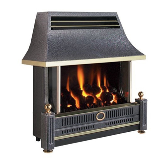
- Page 1 RENOIR RC RADIANT CONVECTOR GAS FIRE Installation, Maintenance & User Instructions Hand these instructions to the user Model No. FRECN0RN2 & FRECR0RN2 are for use on Natural Gas (G20) at a supply pressure of 20 mbar in G.B. / I.E.
-
Page 2: Table Of Contents
CONTENTS PAGE Section 1 Information and Requirements Appliance Information Conditions of Installation Flue & chimney suitability Fireplace / surround suitability Shelf position Side clearance Closure plate Flue & chimney inspection Chimney / flue type information Hearth information 1.10 Spillage monitoring system Section 2 Installation of Fire Packing check list... -
Page 3: Appliance Information
APPLIANCE DATA G20 Models Main injector (1 off) Stereomatic size 380 Cat 82 Pilot type ERTA OXYP PG-83-10 Max. Gross Heat Input : 6.0 kW Min. Gross Heat Input : 3.2 kW Cold Pressure : 20.0 +/- 1.0 mbar (8.0 +/- 0.4 in w.g.) Ignition : 4.5V battery / electronic ignition Electrode Spark Gap :... -
Page 4: Conditions Of Installation
CONDITIONS OF INSTALLATION In Great Britain :- It is law that all gas appliances are installed only by a GAS SAFE registered installer in GB, in accordance with these installation instructions and the Gas Safety (Installation and use) Regulations 1998. Failure to install appliances correctly could lead to prosecution. -
Page 5: Fireplace / Surround Suitability
FIREPLACE / SURROUND SUITABILITY The fire is suitable for hearth mounting or wall mounting. It must not be fitted directly onto a carpet or other combustible material. It must not be fitted to combustible walls. This fire is suitable for the following hearth / surround types: Non-combustible hearths / surrounds. -
Page 6: Chimney / Flue Type Information
1.7.2 Brick / stone built chimneys and any chimney or flue which has been used for an appliance burning fuel other than gas must be thoroughly swept. The base of the chimney / flue must also be thoroughly cleared of debris etc. Any under floor air supply to the fireplace must be completely sealed off. - Page 7 The front opening of the fireplace must be between 305mm and 440mm wide, and between 500mm and 650mm high. If the opening is larger than this, then a surround must be constructed in a suitable non-com bustible material to create an opening to these limits. Allow a minimum flat surface of 20mm around the opening to ensure that the closure plate can be sealed to the fireplace.
-
Page 8: Hearth Information
1.8.3 Fitting to Pre-Cast Flue Installations. The pre-cast opening must be a minimum of 122.7cm 2 or equivalent cross-sectional area and have a minimum effective flue height of 3 metres. This appliance has been tested for use in a pre-cast flue block complying with BS EN 1858. In accordance with BS EN 1858, pre-cast flues built with directly plastered faces (front or rear) are not correctly installed as to ensure proper operation with any type of gas fire. -
Page 9: Installation Of Fire
PACKING CHECK LIST 1 off Canopy / firebox / burner assembly 4 off 8G x 3/8” pozi screws 1 off Flue spigot 1 off DD cover (attached to rear of fire) 1 off Closure plate (attached to rear of fire) 1 off Installation &... - Page 10 2.2.6 Closure plate fitting 2.2.7 Fit the closure plate to the fireplace opening and ensure that it has a flat sealing area of at least 10mm sealed on all sides. See figure 3 below Dimensions stated are for closure plate supplied Check the operation of the chimney as follows:- Fig.
-
Page 11: Fitting The Canopy To The Firebox
FITTING THE CANOPY TO THE FIREBOX 2.3.1 Secure the canopy to the firebox with the four screws (2 off L/H & 2 off R/H) as shown below in figure 4. Fig. 4 2 off R/H canopy fixing screws... -
Page 12: Fitting The Spigot To The Firebox
FITTING THE SPIGOT TO THE FIREBOX 2.4.1 Screw the firebox spigot to the draught diverter with the four screws, 2 off upper (as shown below in figure 5) & 2 off lower screws (not pictured) . Fig. 5 Note : A means of isolation must be provided near to the appliance to facilitate servicing. -
Page 13: Assembly Of The Fuelbed
ASSEMBLY OF THE FUELBED NOTE : The position of the fuel-bed components are critical to the performance of the product. Therefore please ensure that the fuel-bed components are positioned as described in the following section prior to requesting a service call due to soot build up, poor flame pattern etc. 3.1.1 Fit the fuelbed base into the combustion chamber as shown below in figure 6. - Page 14 3.1.3 Fit coal “B” onto the fuelbed base in the position as shown below in figure 8. The coal form has the individual placement letters stamped on the bottom face. Fig. 8 Coal Form “B” 3.1.4 Fit coal “C” onto the fuelbed base in the position as shown below in figure 9.
- Page 15 Fig. 10 Coal Form “D” 3.1.6 Fit coal “E” onto the fuelbed base in the position as shown below in figure 11. The coal from has the individual placement letters stamped on the bottom face. Fig. 11 Coal Form “E” To ensure that the release of fibres from these R.C.F (Refractory Ceramic Fibre) articles is kept to a minimum, during installation and servicing we recommend that you use a HEPA filtered vacuum to remove any dust...
-
Page 16: Fitting The Batteries
FITTING THE BATTERIES 3.2.1 The control valve is located at the base right hand side of the fire, remove the fender if necessary for access by lifting it clear. Fig. 12 Position of battery cover on control valve 3.2.2 Remove the battery compartment cover from the control valve as indicated below in figure 13 and fit the 3 off AA sized alkaline batteries supplied to the control valve unit. -
Page 17: Lighting The Fire Manually Via The Control Valve
LIGHTING THE FIRE MANUALLY VIA THE CONTROL VALVE 3.3.1 These products can be operated manually by using the buttons directly on the fire control in addition to the handset (should the need arise). 3.3.2 To operate the fire press and hold the “power” button as shown below in figure 14 for two seconds, release as soon as the red indicator light shown in figure 14 illuminates. -
Page 18: Setting The Time And Date On The Remote Handset
SETTING THE TIME, DATE & TEMPERATURE ON THE REMOTE HANDSET 3.4.1 Fit the 2 off AA batteries to the handset by removing the cover on the rear of the handset and inserting the batteries, ensure the correct +/- polarity is observed. Following insertion of the batteries the screen displayed will be as shown below in figure 15. - Page 19 Fig. 16 24hr or 12 hr display, press the + or - buttons as shown to toggle between these two settings + button - button 3.4.4 When the 24hr or 12hr time display option has been chosen and you are ready to confirm the setting you want press the SET button on the handset to progress to setting the day of the week as shown overpage in figure 17.
- Page 20 Fig. 17 Celsius or Fahrenheit temperature display, press the + or - buttons as shown to toggle between these two settings and set the correct time of day. + button - button 3.4.7 As shown above in figure 17 the time on the handset can now be set by using the + and - buttons to change the hour to the correct hour then press SET to store and to move to setting the minute.
-
Page 21: Lighting The Fire - Remote Control Models
LIGHTING THE FIRE - REMOTE CONTROL MODELS 3.5.1 Ensure valve power isolation switch is in the on position - see figure 13 and that the time, date & temperature display settings as shown in section 3.4 have been completed. Hold the handset with one hand ensuring your hand is wrapped around the back and that your hand is in contact with both sides of the handset. - Page 22 Fig. 19 - “PILOT” displayed “PILOT” displayed on handset during ignition sequence (typically takes two seconds) Fig. 20 - “MAX” & large flame symbol displayed “MAX FLAME” displayed on handset when burner is lit to maximum rate...
- Page 23 LIGHTING THE APPLIANCE - REMOTE CONTROL MODELS (CONTINUED) 3.5.3 To decrease the heat input level of the burner hold the handset as described in section 3.5.1 to unlock the keypad then press and release the - button. Pressing and releasing the - button will lower the heat input level one step at a time.
-
Page 24: Advanced Settings Of Remote Control Models
3.5.6 If you are not intending to use the fire for a long period (i.e. over the summer months) the battery life can be extended by sliding the power isolator switch to the left (to the “0” position away from the “1” position) on the valve itself, which is located behind the ashpan cover on the fire. - Page 25 Fig. 22 MAN & Zzz symbols flashing illuminated Press mode button to scroll through to MAN & Zzz symbols, then press and release the set button to put the control into the manual snooze mode. 3.6.1.6 Pressing the set button again will now show you the snooze time period remaining.
- Page 26 Fig. 23 Handset showing snooze time period remaining, this can be adjusted from 1 minute to 4:00 hrs by using the + & - buttons on the handset as indicated + button - button 3.6.1.8 To adjust the snooze period use the + and - buttons to increase or decrease the snooze period for any period between 1 minute and 4:00 hours.
- Page 27 3.6.2 Thermostatic mode PLEASE NOTE : Thermostatic mode of this fire will only allow regulation of the room temperature by the fire when it has been already lit via manual operation of the handset. It will not allow the fire to light automatically due to low ambient room temperature and should therefore not be relied upon for frost protection purposes.
- Page 28 3.6.2.4 If at any time the power button is operated during thermostat mode the control will cancel any thermostat operation and return the control to manual mode. 3.6.2.5 IMPORTANT NOTE : Thermostat mode will not light the fire automatically and will only regulate between the maximum and minimum burner setting.
-
Page 29: Checking For Clearance Of Combustion Products
IMPORTANT: THE FIRE MUST ONLY BE OPERATED WITH THE FRONT FENDER IN PLACE CHECKING FOR CLEARANCE OF COMBUSTION PRODUCTS 3.7.1 Close all doors and windows in the room. 3.7.2 Light the fire and turn to the maximum position. After 5 minutes hold the smoke match as shown in figure 25 below. Whilst holding the smoke match in the correct position, approximately 25mm below the lower edge of the draught diverter, ensure that most of the smoke is drawn into the flue aperture. -
Page 30: Final Checks
FINAL CHECKS 3.8.1 Recheck the operation of the fire on all settings. 3.8.2 Make sure that the user knows how to operate the fire and refer them to the user book. 3.8.3 Inform the user that the model number for ordering parts is shown on the rating plate. -
Page 31: General Access For Servicing
MAINTENANCE INSTRUCTIONS Servicing Notes Servicing should be carried out annually by a competent person such as a registered engineer, and must include changing the oxypilot. This is a condition of the manufacturers guarantee. The service should include visually checking the chimney and fire opening for accumulations of debris and a smoke test to check for positive up-draught in the chimney. -
Page 32: Removal Of The Remote Control Valve
Fig. 27 2 off L/H Burner Retaining Screws 2 off R/H Burner Retaining Screws 4.2.5 Remove the four burner retaining screws as indicated in figure 27 above 4.26 Slide the burner assembly to the right, off the injector and remove the from the firebox. -
Page 33: Parts Shortlist
SAFE registered gas installer. The part numbers of the replaceable parts are as follows, these are available from your local Flavel stockist, whose details may be found on the BFM Europe website, address as shown on the back page of this book. -
Page 34: Installation Information / About Your Fire
SECTION FIVE - USER INSTRUCTIONS 5.1 INSTALLATION INFORMATION CONDITIONS OF INSTALLATION It is the law that all gas appliances are installed only by a competent (e.g. GAS SAFE registered) Installer, in G.B. in accordance with the installation instructions and the Gas Safety (Installation and Use) Regulations 1998. Failure to install appliances correctly could lead to prosecution. - Page 35 ABOUT YOUR NEW FLAVEL RENOIR GAS FIRE The Flavel Renoir gas fire incorporates a unique and highly developed heat exchanger which combined with the coal effect gives maximum heat whilst maintaining reasonable running costs Please take the time to fully read these instructions as you will then be able to obtain the most effective and safe operation of your fire.
-
Page 36: Operating Your Fire
OPERATING THE FIRE - REMOTE CONTROL MODELS 5.2.1 Ensure valve power isolation switch is in the on position - see figure 6 Hold the handset with one hand ensuring your hand is wrapped around the back and that your hand is in contact with both sides of the handset. The green light of the “unlock”... - Page 37 Fig. 2 - “PILOT” displayed “PILOT” displayed on handset during ignition sequence (typically takes two seconds) Fig. 3 - “MAX” & large flame symbol displayed “MAX FLAME” displayed on handset when burner is lit to maximum rate...
- Page 38 OPERATING THE APPLIANCE - REMOTE CONTROL MODELS (CONTINUED) 5.2.3 To decrease the heat input level of the burner hold the handset as described in section 5.2.1 to unlock the keypad then press and release the - button. Pressing and releasing the - button will lower the heat input level one step at a time.
- Page 39 5.2.6 If you are not intending to use the fire for a long period (i.e. over the summer months) the battery life can be extended by sliding the power isolator switch to the left (to the “0” position away from the “1” position) on the valve itself, which is located behind the ashpan cover on the fire.
-
Page 40: Manual Operation
MANUAL OPERATION OF THE FIRE 5.3.1 These products can be operated manually should the need arise. The control valve is located at the base of the fire at the right handside, remove the fender by lifting clear, the valve is then located as shown below in figure 5. -
Page 41: Replacing Batteries
5.3.3 To operate the fire press and hold the “power” button as shown in figure 2 on the previous page for two seconds, release as soon as the red indicator light in figure 2 on the previous page illuminates. The burner will start its ignition sequence and light to the maximum heat input level. -
Page 42: Setting The Time, Date & Temperature On The Remote Control Handset
SETTING THE TIME, DATE & TEMPERATURE ON THE REMOTE HANDSET 5.5.1 Fit the 2 off AA batteries to the handset by removing the cover on the rear of the handset and inserting the batteries, ensure the correct +/- polarity is observed. Following insertion of the batteries the screen displayed will be as shown below in figure 7. - Page 43 Fig. 8 24hr or 12 hr display, press the + or - buttons as shown to toggle between these two settings + button - button 5.5.4 When the 24hr or 12hr time display option has been chosen and you are ready to confirm the setting you want press the SET button on the handset to progress to setting the day of the week as shown overpage in figure 9.
- Page 44 Fig. 9 Hour and Minute display, press the + or - buttons as shown to toggle between these two settings and set the correct time of day. + button - button 5.5.7 As shown above in figure 9 the time on the handset can now be set by using the + and - buttons to change the hour to the correct hour then press SET to store and to move to setting the minute.
- Page 45 Fig. 10 Celsius or Fahrenheit temperature display, press the + or - buttons as shown to toggle between these two settings and set the correct time of day. + button - button 5.5.9 The control is now ready for use with the burner. 5.5.10 If the handset is misplaced you can “page it”...
-
Page 46: Advanced Settings Menu Of The Remote Control
ADVANCED SETTINGS MENU OF THE REMOTE CONTROL 5.6.1 Snooze mode in manual operation 5.6.1.1 Snooze mode is a time period which can be set which will turn the fire automatically off after a certain time period has elapsed. 5.6.1.2 Hold the handset with one hand ensuring your hand is wrapped around the back and that your hand is in contact with both sides of the handset. - Page 47 5.6.1.6 Pressing the set button again will now show you the snooze time period remaining. The snooze time period can be adjusted by pressing the + or - buttons on the handset. This time period can be set ranging from 1 minute to 4:00 hours.
- Page 48 5.6.2 Thermostatic mode PLEASE NOTE : Thermostatic mode of this fire will only allow regulation of the room temperature by the fire when it has been already lit via manual operation of the handset. It will not allow the fire to light automatically due to low ambient room temperature and should therefore not be relied upon for frost protection purposes.
-
Page 49: Cleaning
5.6.2.4 If at any time the power button is operated during thermostat mode the control will cancel any thermostat operation and return the control to manual mode. 5.6.2.5 IMPORTANT NOTE : Thermostat mode will not light the fire automatically and will only regulate between the maximum and minimum burner setting. -
Page 50: Removal / Re-Fitting The Fuel-Bed Ceramics
REMOVAL & RE-ASSEMBLY OF THE FUELBED NOTE : The position of the fuel-bed components are critical to the performance of the product. Therefore please ensure that the fuel-bed components are positioned as described in the following section prior to requesting a service call due to soot build up, poor flame pattern etc. 5.8.1 Fit the fuelbed base into the combustion chamber as shown below in figure 14. - Page 51 5.8.3 Fit coal “B” onto the fuelbed base in the position as shown below in figure 16. The coal form has the individual placement letters stamped on the bottom face. Fig. 16 Coal Form “B” 5.8.4 Fit coal “C” onto the fuelbed base in the position as shown below in figure 17.
- Page 52 5.8.5 Fit coal “D” onto the fuelbed base in the position as shown below in figure 18. The coal form has the individual placement letters stamped on the bottom face. Fig. 18 Coal Form “D” 5.8.6 Fit coal “E” onto the fuelbed base in the position as shown below in figure 19.
-
Page 53: User Replaceable Parts
To ensure that the release of fibres from these R.C.F (Refractory Ceramic Fibre) articles is kept to a minimum, during installation and servicing we recommend that you use a HEPA filtered vacuum to remove any dust accumulated in and around the appliance before and after working on the appliance. - Page 54 Due to our policy of continual improvement and development the exact accuracy of descriptions and illustrations cannot be guaranteed. TROUBLE SHOOTING ADVICE FOR REMOTE CONTROL MODELS PRIOR TO REQUESTING A SERVICE CALL Please locate the Indicator light on the control valve, located behind the fender at the right hand side of the fire (see figure 5 & 6 on page 40), if it shows any of the following flashing sequences then the problem requires the batteries in the control valve and / or handset changing, be advised that service calls as a result of batteries requiring...
Need help?
Do you have a question about the RENOIR RC and is the answer not in the manual?
Questions and answers