Table of Contents
Advertisement
Advertisement
Table of Contents

Related Manuals for Remotec ZTS-100


Summary of Contents for Remotec ZTS-100
- Page 1 ZTS-100 Z-Thermostat USER MANUAL...
-
Page 2: Table Of Contents
Setting Mode Temperature Scale selection (for SIMPLE mode) Setting Schedule Z-Wave Add (Inclusion) / Delete (Exclusion) Mode Add ZTS-100 to Gateway / Controller Z-Wave network Delete ZTS-100 from Gateway / Controller Z-Wave network Support Association Command Class Z-Wave Configuration Command... -
Page 3: Introduction
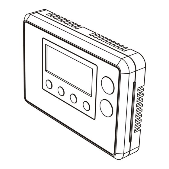
ZTS-100 Z-Thermostat Introduction Welcome to the Z-Wave world of home automation, your ZTS-100 Z-Thermostat (Figure 1) is a comfort control master that allows to control your room temperature with programmable time schedule WAKE, AWAY, HOME and SLEEP event which can maximize energy conservation and comfort while minimizing the effort required to maintain the appropriate temperature in your home whether you are at home or away. -
Page 4: Features List
Features List HVAC System Type Compatible: - Standard (gas/electric) or Heat Pump Multistage System Compatible: - Standard HVAC Systems: 2 stage heating, 1 stage cooling - Heat Pump Systems: 2 stage heating, 1 stage cooling Heat Pump change over valve: - Selectable change over with cool or with heat Power: - Powered by alkaline batteries AA x 4pcs or 24Vac... -
Page 5: Glossary
NWI is a feature supported by a new frame type named Explorer which enables the Z-Wave protocol to implement Adaptive Source Routing. A collection of Z-Wave devices is controlled by primary and secondary controllers operating on the same system. A Z- Z-Wave... -
Page 6: Physical Installation And Wiring
- Use new batteries of the recommended type and size only. - Never mix used and new batteries together. - To avoid chemical leaks, remove batteries from the ZTS-100 if you do not intend to use the unit for an extended period of time. -
Page 7: Installation Location
24Vac Power for Heating 24Vac Common Important! The ZTS-100 can be powered by alkaline batteries AA x 4pcs or 24Vac. Connect the "24Vac Common" (typically the black wire/terminal) and "24Vac Power" (typically the Red wire/terminal) from the HVAC system to the ZTS-100 HVAC System terminal block "C"... - Page 8 When wiring split systems, wire the heating systems "24Vac Power" (red wire) to the ZTS-100 "RH" terminal, and wire the cooling systems "24Vac Power" to the ZTS-100 "RC" terminal. Also wire the cooling systems "24Vac Common" to the ZTS-100 "C" terminals.
-
Page 9: Jumper Settings For Electh-Hpump And He-Hg
Set to HG for Gas heat-fan controlled unit (Default) Set to HE for Electrical heat-fan controlled unit Mounting: 1. Open the ZTS-100 by pushing the hook (Figure 5) 2. Install AAx4pcs batteries if using battery power (Alkaline batteries are recommended) 3. -
Page 10: Zts-100 Z-Thermostat Operations
ZTS-100 Z-Thermostat Operations The following section will guide you through the set up processes for your ZTS-100. Different listening nodes are able to act as repeaters to enlarge the network range. Please note that all Z-Wave thermostat controllers are designed and manufactured... -
Page 11: Description Of Function Keys
Description of Function Keys Symbol Key Description Increase value / Toggle selection Decrease value / Toggle selection Select fan mode; also the Backward function key in some menus Change operation mode; also the Forward function key in some menus Select program mode: PROG ON, OVERRIDE and PERMANENT OVERRIDE;... -
Page 12: Select Fan Mode
Select Fan Mode LCD indication Step Procedure / Description Press "Fan" key once to change the Fan mode: FAN AUTO -> FAN ON WAKE FAN AUTO: Electric heat (HE): Fan runs only when Heating/Cooling is COOL running. FAN AUTO Gas heat (HG): Fan runs only when Cooling is running. -
Page 13: Override/Permanent Override
Override/Permanent Override Note 1: Override/Permanent Override is only available in HEAT, COOL or AUTO mode. Step Procedure / Description LCD indication Press "Prog" key once to select PROG mode: OVERRIDE or PERMANENT HEAT OVERRIDE at Home page. OVERRIDE TARGET FAN AUTO HEAT Press Up/Down key to adjust set point OVERRIDE... -
Page 14: Setting Mode
Setting Mode (Set Day, Clock, 12/24 hour, F/C, Swing and Differential) Symbol Setting Mode Key Description Increase value / Toggle selection Decrease value / Toggle selection Backward to previous setting Forward to next setting Confirm and go to next setting Confirm and go back to Home Setting Mode Step... - Page 15 Step Procedure / Description LCD indication Day will keep flashing, press Up/Down key to set day from MO-SU. Press "Prog" key once to confirm the setting and it will go to hour setting. Hour will keep flashing, press Up/Down key to set hour. Press "Prog"...
-
Page 16: Temperature Scale Selection (For Simple Mode)
Step Procedure / Description LCD indication Press "Prog" key once to confirm the setting and it will go to differential set point setting. DIFF Press Up/Down key to set the differential set point setting. (Range is from 0.5 C to 2 C or 1 F to 4 F ) Press "Prog"... -
Page 17: Setting Schedule
Setting Schedule Default Schedule: Event Time Heat Cool WAKE 6:00AM 70 F (21 C) 78 F (26 C) AWAY 8:00AM 62 F (17 C) 85 F (29 C) HOME 6:00PM 70 F (21 C) 78 F (26 C) SLEEP 10:00PM 62 F (17 C) 82 F (28 C) WAKE... - Page 18 Step Procedure / Description LCD indication MO TU WE TH FR WAKE AWAY Press "Prog" key once to confirm the setting and it will go to event mode. HOME Press Up/Down key to select the event (WAKE -> AWAY -> HOME -> SLEEP). SLEEP Press "Prog"...
-
Page 19: Z-Wave Add (Inclusion) / Delete (Exclusion) Mode
Follow the program UI to complete the whole scheduling or press Home key once to save and exit. Z-Wave Add (Inclusion) / Delete (Exclusion) Mode Symbol Inclusion and Exclusion Mode Key Description Add (Inclusion) / Delete (Exclusion) - Page 20 Please perform the Delete (Exclusion) before adding into the new Z-Wave network. Note 2: User can control the ZTS-100 through gateway or controller after adding into the Z-Wave network. ZTS-100 can be configured as either "Frequently Listening Routing Slaves"...
-
Page 21: Add Zts-100 To Gateway / Controller Z-Wave Network
Important: It is not allow changing ZTS-100 operation mode by change of power source. It is need to follow the above steps to change ZTS-100 operation mode. Add (Inclusion) ZTS-100 to Gateway / Controller Z-Wave network Step Procedure / Description... - Page 22 5 nodes can be assigned in these 2 association groups. Association group_1: - ZTS-100 will send out basic set command 0xFF automatically once Heat Pump operation has been started in heating mode. - ZTS-100 will send out basic set command 0x00 automatically once Heat Pump operation has been stopped in heating mode.
-
Page 23: Support Association Command Class
Z-Wave Configuration Command Parameter value range Parameter Number Definitions 0x01 = 0.5 C / 1 F 0x02 = 1.0 C / 2 F (default) 1 (0x01) Swing 0x03 = 1.5 C / 3 F 0x04 = 2.0 C / 4 F 0x01 = 0.5 C / 1 F... -
Page 24: Filter Counter
Filter Counter LCD indication Step Procedure / Description Press and hold "Fan" key for 2 seconds to check the filter counter. FILTER The "usage hours" will be shown on screen. Press and hold "Prog" key for 2 seconds FILTER to reset the filter counter after replace a new filter. -
Page 25: Reset Zts-100 To Factory Default Settings
Reset ZTS-100 to Factory Default Settings LCD indication Step Procedure / Description Press and hold "Fan" + "Mode" keys for 2 seconds to entry the reset mode. Press Up/Down key to toggle Yes/No selection. Press "Prog" key once to confirm the action. -
Page 26: Defrost Indication
Energy Saving Mode Step Procedure / Description LCD indication User can enable/disable energy saving mode by using Z-Wave BASIC set command only. => Enable energy saving mode Basic set value = 0x00 (off mode) (energy saving mode will be mapped to off mode) =>... -
Page 27: Advanced Recovery Indication
Advanced Recovery Indication Step Procedure / Description LCD indication The Advanced Recovery feature allows heating and cooling systems to gradually recover from an energy-saving set point temperature to a comfort set point temperature. Advanced Recovery calculates the time needed to adjust the temperature to the next program setting. -
Page 28: Frequently Asked Questions
Z-Wave logo. Q Can I use 2 or more ZTS-100 in my house? What is the max. units if yes? A Yes and it is very depends on the capability of gateway / controller. For example, gateway can supports up to 8, 16 or 32 ZTS-100 in a network. - Page 29 COOL Mode: thermostat controls the temperature according to the following diagram Output Set point Cool Turn off Turn on Temperature Swing Example for Cooling: (Set point = 80 F, Swing = 1 F) => Cooler turns on when room temp is 81 F and off at 79 F. AUTO: thermostat controls the temperature according to the following diagram Output Heat Set point...
-
Page 30: Technical Specifications
Operating: 32-122 F / 0-50 C Temperature Storage: 23-140 F / -5-60 C Dimension (L x H x T) 145mm x 100mm x 25mm Weight 170g (Batteries excluded) Z-Wave device type Basic Device Class: Routing_Slave Generic Device Class: Thermostat Specific Device Class: Thermostat general v2... -
Page 31: Checking Accessories
COMMAND_CLASS_CONFIGURATION Checking Accessories After opening the cover of the packaging box, check that the following accessories are included. - ZTS-100: Z-Thermostat - Screw + Wall Anchor x 4pcs - User Manual FCC Notice This device complies with Part 15 of the FCC rules. Operation is subject to the... -
Page 32: Warnings
NOTE: This equipment has been tested and found to comply with the limits for a Class B digital device, pursuant to Part 15 of the FCC Rules. These limits are designed to provide reasonable protection against harmful interference in a residential installation. This equipment generates, uses and can radiate radio frequency energy and, if not installed and used in accordance with the instructions, may cause harmful interference to radio communications.
Need help?
Do you have a question about the ZTS-100 and is the answer not in the manual?
Questions and answers