Table of Contents
Advertisement
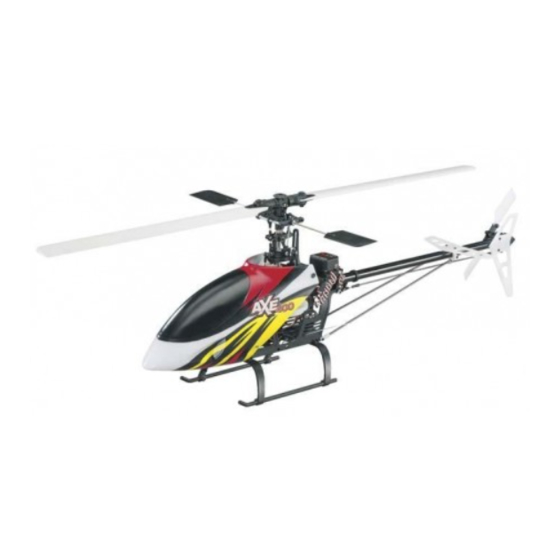
Rotor Span: 27.5 in [700mm]
Height: 9.3 in [236 mm]
Length: 24 in [610mm]
Weight: 18.4 oz [521g] no battery,
25 oz [708g] w/fl ight battery (GPMP0520)
Motor: 420 Brushless out-runner motor
Radio: Futaba
®
6EX 6-channel 2.4GHz FASST transmitter
Futaba R606FS 6-channel 2.4GHz FASST receiver
Servos: Futaba S3114 micro HT servo
Gyro: Heli-Max
™
Heading Lock HM 4000 Gyro w/remote dual gain
WARNING!! Read the entire instruction sheet included with your battery and charger. Failure to follow all
instructions could cause permanent damage to the battery, charger or its surroundings, and cause bodily harm!
• Never charge in excess of 4.20V per cell.
• If the battery should become damaged, discard the
battery. Do not attempt to use a damaged battery.
• Do not leave the charger unattended while charging.
Disconnect the battery and remove input power from the
charger immediately if either becomes hot! However, it is
normal for the charger to get warm.
• Disconnect the battery from the charger and carefully
move the battery to a fi reproof location if the battery
begins to swell or smoke!
• Never charge at currents greater than 1C.
• Always charge in a fi reproof location.
• Never trickle charge.
• Never allow the battery temperature to exceed 150° F
[65° C].
• Never disassemble or modify pack wiring in any way or
puncture cells.
• Never discharge below 2.5V per cell.
READ THROUGH THIS MANUAL BEFORE STARTING CONSTRUCTION.
IT CONTAINS IMPORTANT INSTRUCTIONS AND WARNINGS
CONCERNING THE ASSEMBLY AND USE OF THIS MODEL.
IMPORTANT PRECAUTIONS
• Do not allow water, moisture or foreign objects into
the charger.
• Do not block the air intake holes, which could cause the
charger to overheat.
• Do not place the charger or any battery on a fl ammable
surface or near a combustible material while in use.
• Do not charge on a carpet, cluttered workbench, paper,
plastic, vinyl, leather, wood, or inside an R/C model.
• Never charge inside a full sized vehicle.
• Always disconnect the battery from the charger and the
power supply from the charger when not in use.
• Do not attempt to charge a battery if it is swollen or hot.
• ALWAYS KEEP OUT OF REACH OF CHILDREN.
™
INSTRUCTION MANUAL
Champaign, Illinois
(217) 398-8970
helihotline@hobbico.com
Advertisement
Table of Contents

Related Manuals for Heli-Max AXE 400 RTF


Summary of Contents for Heli-Max AXE 400 RTF
-
Page 1: Instruction Manual
6EX 6-channel 2.4GHz FASST transmitter Futaba R606FS 6-channel 2.4GHz FASST receiver Servos: Futaba S3114 micro HT servo INSTRUCTION MANUAL Gyro: Heli-Max ™ Heading Lock HM 4000 Gyro w/remote dual gain IMPORTANT PRECAUTIONS WARNING!! Read the entire instruction sheet included with your battery and charger. Failure to follow all instructions could cause permanent damage to the battery, charger or its surroundings, and cause bodily harm! •... -
Page 2: Table Of Contents
For the latest technical updates or manual corrections • The spinning blades of a model helicopter can cause to the AXE 400 3D RTF visit the Heli-Max web site at serious injury. When choosing a fl ying site for your AXE www.helimax-rc.com. -
Page 3: Items Required
In that Heli-Max has no control over the fi nal assembly or material used for fi nal assembly, no liability shall be Remember: Take your time and follow the instructions to assumed nor accepted for any damage resulting from the build a safe and enjoyable model. -
Page 4: Kit Contents
KIT CONTENTS 1. Transmitter 2. Helicopter OPERATIONAL WARNINGS CAUTION! A separate Battery Eliminator Circuit (BEC) which will reduce the power output to safe levels when the ® must be used if you decide to change the stock (Futaba safe operating temperatures have been exceeded. If this has S3114) servos to some other type of analog or digital servos. -
Page 5: Electric Motor Warning
ELECTRIC MOTOR WARNING The Dual Rate Switch changes the control rate of the helicopter. The High Rate provides the maximum control which is necessary for 3D fl ight and aerobatics. The low rate reduces control throw which makes the model easier to fl y. The low rate is recommended for your fi... -
Page 6: Controls
LEFT CYCLIC The Idle-Up function is disabled within the transmitter for safety. If you are beginning aerobatics or are an experienced pilot and Moving the cyclic stick left will cause the helicopter to tilt left feel you have a need for the Idle Up function, then please follow and start moving in that direction. -
Page 7: Get The Model Ready To Fly
INCREASING THROTTLE & COLLECTIVE PITCH - CLIMB TAIL ROTOR RIGHT Moving the collective stick forward (away from you) will cause Moving the tail rotor stick right will cause the helicopter nose the helicopter to climb higher. to move right (clockwise). DECREASING THROTTLE &... - Page 8 MIX WARNING In the following step do not connect the fl ight battery to the ESC until you are instructed to do so. With the power lead facing downward, place the fl ight battery onto the battery tray and attach using the battery strap as shown. If the transmitter is turned on with the Throttle Hold or Idle Up function switched on, the screen will show "MIX"...
-
Page 9: Tracking The Main Blades
CONNECTING THE FLIGHT BATTERY TRACKING THE MAIN BLADES WARNING! Always wear safety glasses when operating this model or Tracking the Main Blades. Before connecting the fl ight battery verify that the Idle Up Switch and Throttle Hold switches are off and verify that the throttle stick is in the lowest position. - Page 10 the blades are the same. If they are not, adjust one of the to nose-in hovering, and try to lengthen the delay between linkages to bring the blades into the same plane. transitions. This will allow you to practice nose-in and still give you a chance to get out of trouble.
-
Page 11: Quick Reference To Transmitter Functions
periods of time. As you become accustomed to the reversed controls, you will extend the time inverted. It is very diffi cult QUICK REFERENCE TO and will take some practice. Also, make sure you have plenty TRANSMITTER FUNCTIONS of altitude for recovery if needed. ACTIVATING THE IDLE UP FUNCTION Please refer to the included manufacturer’s instruction manual for complete details for each function. -
Page 12: Linkage Rod Lengths
LINKAGE ROD LENGTHS ORDERING PARTS Replacement parts for the Heli-Max AXE 400 3D RTF are available using the order numbers in the Parts List on page 18. The fastest, most economical service can be provided by your hobby dealer. To locate a hobby dealer, visit the Hobbico web site at www.hobbico.com. - Page 13 23 HMXE8501 ..Swashplate ........1 OPTIONAL PARTS 24 HMXE8512 ..Mixing Arms ........16 Stock # ....Description 25 HMXE8502 ..Washout Base ........1 26 HMXE8503 ..Main Shaft .........1 HMXE7493 ..CNC Mixer Arms (2) AXE 400 27 HMXE8504 ..Seesaw Bushing Set ......2 HMXE7483 ..
-
Page 14: Exploded Views
EXPLODED VIEWS MAIN FRAME 3 Screw... - Page 15 TAIL BOOM ASSEMBLY 32 54 ROTOR HEAD...
-
Page 16: Parts Images
Blade Grip Bolt Set 1Set Main Blade Grip Set 1Set Dampening Shim Set 1Set Bearings Main Grips/Tail Shaft Part #HMXE8506 Part #HMXE8507 Part #HMXE8508 Part #HMXE8827 6Pcs EVPL #29 EVPL #30 EVPL #31 EVPL #31 Head Dampeners 4Pcs Feathering Spindle Head Block 1Set Mixing Arms... -
Page 18: Optional Parts
Tail Rotor Hub 1Set Tail Rotor Grips Tail Rotor Blades Main Rotor Blades 2Pcs Part #HMXE8648 Part #HMXE8649 Part #HMXE8426 Part #HMXM8323 EVPL #57 EVPL #58 EVPL #59 EVPL #60 Main Rotor Gear Tail Rotor Drive Belt Without One-Way Bearing Part #HMXM2009 Part #HMXM2009 Part #HMXM8029... - Page 19 CNC Swashplate (1 Pc) CNC Tail Case (1 Pc) CNC Tail Drive Belt Pulley (1 Pc) Part # HMXE7488 Part # HMXE7489 Part # HMXE7490 CNC Counter Drive Belt Pulley (1 Pc) CNC Tail Blade Grips (2 Pcs) CNC Mixer Arms (2 Pcs) Part # HMXE7491 Part # HMXE7492 Part # HMXE7493...
- Page 20 Entire Contents © Copyright 2009 HMXE0800 Manual 1.1...
Need help?
Do you have a question about the AXE 400 RTF and is the answer not in the manual?
Questions and answers