Table of Contents
Advertisement
Quick Links
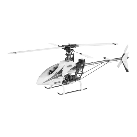
Rotor Diameter: 23 in [588 mm]
Weight: 20.5–23 oz [580–650 g]
Length: 25 in [630 mm]
Height: 9 in [225 mm]
Motor: 200W brushless, 28 mm diameter
Heli-Max
™
guarantees this kit to be free from defects in both
material and workmanship at the date of purchase. This warranty
does not cover any component parts damaged by use or
modification. In no case shall Heli-Max's liability exceed the
original cost of the purchased kit. Further, Heli-Max reserves
the right to change or modify this warranty without notice.
In that Heli-Max has no control over the final assembly or material
used for final assembly, no liability shall be assumed nor accepted
for any damage resulting from the use by the user of the final
user-assembled product. By the act of using the user-assembled
product, the user accepts all resulting liability.
READ THROUGH THIS INSTRUCTION MANUAL
FIRST. IT CONTAINS IMPORTANT INSTRUCTIONS
AND WARNINGS CONCERNING THE ASSEMBLY
AND USE OF THIS MODEL.
Entire Contents © Copyright 2005
INSTRUCTION MANUAL
WARRANTY
If the buyer is not prepared to accept the liability associated
with the use of this product, the buyer is advised to return
this kit immediately in new and unused condition to the place
of purchase.
To make a warranty claim, send
the defective part or item to
Hobby Services at this address.
Include a letter stating your name, return shipping address, as
much contact information as possible (daytime telephone number,
fax number, e-mail address), a detailed description of the problem
and a photocopy of the purchase receipt. Upon receipt of the
package the problem will be evaluated as quickly as possible.
™
Hobby Services
3002 N. Apollo Dr. Suite 1
Champaign IL 61822
Champaign, Illinois
(217) 398-8970
E-mail: helicoptersupport@greatplanes.com
HMXZ7011 for HMXE0205 V1.0
USA
Advertisement
Table of Contents

Related Manuals for Heli-Max MX400 PRO


Summary of Contents for Heli-Max MX400 PRO
-
Page 1: Instruction Manual
Champaign IL 61822 Hobby Services at this address. In that Heli-Max has no control over the final assembly or material used for final assembly, no liability shall be assumed nor accepted Include a letter stating your name, return shipping address, as... -
Page 2: Table Of Contents
DECISIONS YOU MUST MAKE....2 In the hands of a capable pilot, the MX400 Pro is an ASSEMBLE THE TAIL......3 impressive 3D performer. -
Page 3: Assemble The Tail
The Futaba GY240 gyro (FUTM0809) is an ASSEMBLE THE TAIL excellent choice. Battery The MX400 Pro requires a 1200-2000 mAh 3-cell Lithium- Polymer (LiPo) battery capable of delivering 15A of current continuously. We recommend the ElectriFly ™ 3S 1250 mAh pack (GPMP0823). -
Page 4: Install The Pushrods & Servos
Check to see that the ball link runs freely on the assembly firmly in place. Do not over-tighten. ball, and loosen it if necessary using the following Heli-Max Tip. - Page 5 5. Center the rudder servo and install the servo arm. With the servo centered, the tailrotor should be at approximately HELI-MAX TIP zero pitch. If it is not, adjust the length of the rudder pushrod. How to adjust the fit of ball links.
- Page 6 ❏ ❏ 8. Drill 1/16" pilot holes in the outer hole on the aileron 10. Using two plastic servo nuts, install the elevator servo servo arm and install a ball in each end. Center the servo as shown. and install the arm onto it. ❏...
- Page 7 ❏ 13. Install a ball link on the inside of the elevator servo horn and install the elevator pushrod as shown. With the elevator servo centered, the elevator control horn should be vertical. If it is not, adjust the length of the elevator pushrod until it is.
-
Page 8: Final Assembly & Setup
FINAL ASSEMBLY & SETUP ❏ 3. Install the gyro directly under the main shaft. Connect your rudder servo to the gyro’s output port. Alternately, the gyro can be installed on top of the rear end of the main frames. Use a piece of foam tape to isolate the gyro against vibration, and secure it with a tie wrap. - Page 9 ❏ 9. Cut the window out of the canopy, and trim the flashing from around the rear opening. ❏ 5. Install the speed control on the bottom of the helicopter with double-sided tape. Connect the ESC to the motor and the receiver.
-
Page 10: Check The Control Directions
❏ ❏ 1. Attach the “loop” side of the hook-and-loop material to 1. Balance your main blades using the Heli-Max Blade the battery. Mount the battery to the battery tray. Balancer (HMXR4855). Do so according to the instructions that came with your balancer. -
Page 11: Set Control Throws
SET CONTROL THROWS RANGE CHECK Ground check the operational range of your radio before the first flight of the day. With the transmitter antenna collapsed and the receiver and transmitter on, you should be able to walk at least 50 feet away from the model and still have control. Have an assistant stand by your model and, while you work the controls, tell you what the servos are doing. -
Page 12: Mx400 Parts List
HMXE9619 .....4003-317....Tail Stabilizer Set Pro HMXE8620 .....ARK-203 ....Aluminum Top Dome HMXE9422 .....4003-318....Tail Case Plate w/Bearing Pro HMXE9421 .....ARK-204 ....Aluminum Tail Case Set HMXE7506 .....4004-062....Decal Sheet MX400 Pro HMXE7000 .....ARK-205 ....CCPM Upgrade Kit HMXE8312 .....4011-001....Collar 3x5x4 mm HMXE7950 .....ARK-209 ....Carbon Frame Full Set HMXE9060 .....4012-007....Wash-Out Control Arm... -
Page 13: Parts Drawings
ROTOR HEAD ARK-222 4001-123 Full Set 4013-010 4102-004 4043-007 4012-020 4045-001 4011-010 4045-001 4014-001 4012-010 4603-003 4001-122 4043-007 4202-007 MIXING LEVERS... - Page 14 PITCH LINKS 4001-120 FLYBAR 4013-006 4001-106 4603-003...
- Page 15 BLADE GRIPS ARK-203 4202-007 4043-007 4001-102 4045-003 4703-055 ARK-220 4011-001 4012-112 4016-002 5400-115 4013-001 BLADE ATTACHMENT...
- Page 16 PITCH LEVER LINKAGES 4001-116 4001-114 4043-002...
- Page 17 TAIL DRIVE MAIN SHAFT SWASH PLATE...
- Page 18 MAIN FRAME LOWER FRAME...
- Page 19 LANDING GEAR TAIL BOOM...
-
Page 20: Pitch Gauge
TAIL ROTOR TAIL DRIVE GEARBOX CANOPY PITCH TEMPLATE...
Need help?
Do you have a question about the MX400 PRO and is the answer not in the manual?
Questions and answers