Table of Contents
Advertisement
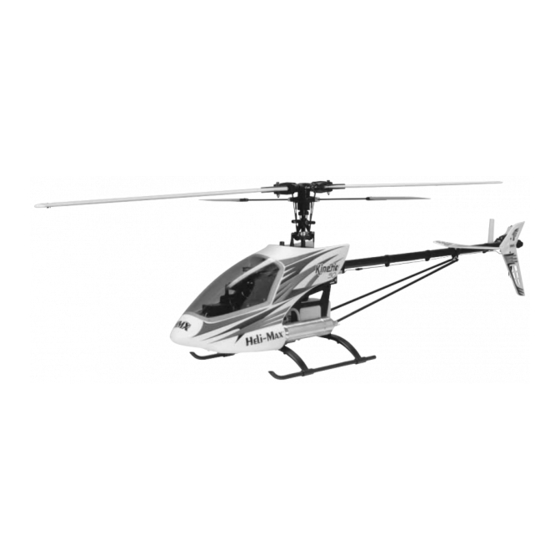
Rotor Span: 52.75 in [1340mm]
Weight: 7.5 lb [3402g]
Length: 47 in [1194mm]
Height: 15.25 in [387mm]
Engine: .46-.51 cu in [7.5-8cc] 2-Stroke
Gear Ratio: 9.1:1 (Main)
5:1 (Tail)
Heli-Max
guarantees this kit to be free from defects in both
™
materials and workmanship at the date of purchase. This
warranty does not cover any component parts damaged by use
or modification. In no case shall Heli-Max's liability exceed the
original cost of the purchased kit. Further, Heli-Max reserves
the right to change or modify this warranty without notice.
In that Heli-Max has no control over the final assembly or material
used for final assembly, no liability shall be assumed nor accepted
for any damage resulting from the use by the user of the final
user-assembled product. By the act of using the user-assembled
product, the user accepts all resulting liability.
If the buyer is not prepared to accept the liability associated
with the use of this product, the buyer is advised to return
this kit immediately in new and unused condition to the place
of purchase.
READ THROUGH THIS INSTRUCTION MANUAL
FIRST. IT CONTAINS IMPORTANT INSTRUCTIONS
AND WARNINGS CONCERNING THE ASSEMBLY
AND USE OF THIS MODEL.
Entire Contents © Copyright 2007
TM
INSTRUCTION MANUAL
WARRANTY
To make a warranty claim, send the defective part or item to
Hobby Services at this address.
Include a letter stating your name, return shipping address, as
much contact information as possible (daytime telephone
number, fax number, e-mail address), a detailed description of the
problem and a photocopy of the purchase receipt. Upon receipt of
the package the problem will be evaluated as quickly as possible.
Hobby Services
3002 N. Apollo Dr., Suite 1
Champaign, IL 61822
USA
Champaign, Illinois
(217) 398-8970, Extension 6
E-mail: helihotline@hobbico.com
HMXZ7013 for HMXE0250 V1.1
TM
Advertisement
Table of Contents

Subscribe to Our Youtube Channel
Related Manuals for Heli-Max Kinetic 50


Summary of Contents for Heli-Max Kinetic 50
-
Page 1: Instruction Manual
3002 N. Apollo Dr., Suite 1 Champaign, IL 61822 In that Heli-Max has no control over the final assembly or material used for final assembly, no liability shall be assumed nor accepted for any damage resulting from the use by the user of the final user-assembled product. -
Page 2: Table Of Contents
Intermediate and Basic Aerobatic Curves ......23 Advanced 3D and Aerobatic Curves ......23 For the latest technical updates or manual corrections to the SERVO SETUP AND LINKAGES ........24 Kinetic .50 visit the Heli-Max web site at: Forward/Aft Cyclic Setup ..........24 Left/Right Cyclic Setup ............24 www.helimax-rc.com Collective Pitch Setup............25... -
Page 3: Safety Precautions
For any helicopter to perform to its full potential, it must be equipped with all the right gear (servos, batteries, receiver, etc). While other brands of equipment can be used, the equipment SAFETY PRECAUTIONS we recommend has the advantage of being extensively tested and proven effective. -
Page 4: Decisions You Must Make
Great Planes 3' Silicone Fuel Tubing (GPMR4131) ❏ Great Planes Fuel Filter (GPMQ4150) ❏ O.S. Remote Glow Plug Adapter (OSMG2401) ❏ Heli-Max .30 – .50 Size Blade Holder (GPMQ4150) DECISIONS YOU MUST MAKE FIELD EQUIPMENT ❏ Heli-Max One-Way Start Shaft (HMXP2050) ❏... -
Page 5: Important Building Notes
Kit Contents list. Machine screws are designated by a diameter and threads per mm/inch. This type of screw is referred to as Heli-Max Product Support: Socket Head Cap Screw (SHCS) through out this manual. 3002 N. Apollo Drive, Suite 1,... -
Page 6: Assembly Instructions
ASSEMBLY INSTRUCTIONS LOWER FRAME AND TANK ❏ 2. Cut the clunk line to a length of 60mm and slide it onto the short brass tubing. Slide the fuel tubing over the clunk. Cut a piece of the larger silicone tubing to 30mm with an angled cut as shown above. - Page 7 ❏ Note: You will need to lock the crankshaft while tightening 3. Apply thread lock to the crankshaft of the engine and the clutch and nut. We recommend using a O.S. Crankshaft thread the clutch onto the engine. Use a thick piece of Clamp .32-.46 (OSMR1004) as shown above.
-
Page 8: Upper Frame And Servo Frame Installation
❏ 6. Install the engine onto the mount using thread locker Bag 9 Contents: Servo Tray Set, 3x12mm Cap Screw (4), 3x8mm Self-Tapping Screw (2), 3x8mm Mashine Screw (2), and the four 3x16mm screws provided. 3x8x1mm Flat Washer (4), 3x12mm Self-Tapping Screw ❏... -
Page 9: Main Rotor Head Assembly And Installation
❏ 3. Apply thread locker to one 3x12mm socket head cap 51mm screw. Install the screw and washer as shown above. Repeat on the opposite side of the frame. (Sketch not to scale) ❏ 6. Install the silver 3x6mm silver Phillips screw into the lower part of the servo frame as shown above. - Page 10 ❏ 5. Install the two 3x3mm set screws into the flybar ❏ 2. Remove the set screws from the flybar arms and align the weights. Slide the weights onto the flybar with the beveled hole with the flat spot on the flybar. Apply a small amount of end facing inward.
-
Page 11: Tail Boom And Gearbox Assembly
42mm Bag 8-2 Contents: 3x16mm SHCS, 3x10mm SHCS, 3mm Nylon Lock Nuts (Sketch not to scale) ❏ 8. Check the two linkages and verify they are 42mm. Install the two linkages onto the flybar control arm and the washout arm as shown above. Temporarily install the 4mm main blade bolts into the blade grips. -
Page 12: Tail Blades
❏ Install the plastic tail blades as shown above using a 3x16mm SHCS and 3mm Nylon lock nuts. Tighten until the blades will support their own weight. Both tail blades need to be tightened equally. HORIZONTAL AND VERTICAL FINS ❏ 3. -
Page 13: Tail Boom Supports
❏ ❏ 2. Install the horizontal fin clamp. Using two 3x16mm self- 1. Install the boom supports using two 3x10mm SHCS and tapping screws, attach the horizontal fin to the clamp. Do not two 3mm nylon lock nuts. You will need a pair of small needle completely tighten bolts at this time as you will need to adjust nose pliers for this step. -
Page 14: Landing Gear
LANDING GEAR ❏ 3. Install the four 3x4mm set screws into the inside of the Bag 6 Contents: 3x20mm SHCS (4), Plastic Spacers, struts. These are used to lock the struts to the skids. Please 3mm Nylon Lock Nut (4), 3x4mm Set Screws (4) be careful not to overtighten. -
Page 15: Horizontal Fin Alignment
EQUIPMENT INSTALLATION SERVOS AND POWER SWITCH Please follow the manufacturer’s instructions for your servos. Install the grommets and eyelets and remove the servo arm screws and servo arms. ❏ 2. Thread the plastic tail rotor pushrod coupler onto the short pushrod at least 1/4" [6.4mm]. If you find the coupler difficult to thread on you can use a hobby knife to chamfer the ball link. -
Page 16: Battery, Receiver And Gyro
❏ ❏ 4. The collective and throttle servos are mounted on the 8. Install the tail rotor servo as shown using four 2.6x10mm inside of the frame. Slide the throttle servo into the frame as screws and two plastic servo nuts. shown above. -
Page 17: Receiver Antenna
RECEIVER CHANNEL ASSIGNMENTS LEFT / RIGHT FOR/AFT RECEIVER TYPE CYCLIC CYCLIC TAIL ROTOR GYRO GAIN COLLECTIVE THROTTLE Futaba PPM / FM CH 1 CH 2 CH 4 CH 5 CH 6 CH 3 Futaba PCM 1024 CH 1 CH 2 CH 4 CH 5 CH 6... -
Page 18: Radio Setup (Futaba: 6Exh,7Ch,9Ch)
SETUP QUICK REFERENCE L/R CYCLIC F/A CYCLIC THROTTLE TAIL ROTOR GYRO COLLECTIVE EPA/ATV 110% / 110% 110% / 110% 100% / 90% 100% / 100% 100% / 100% 100% / 100% 100% 100% 100% -30% -30% -30% Reverse (Futaba) 1 – Normal 2 –... -
Page 19: Set Modulation Type
❏ MODEL NAME 2. Futaba T7CH: Select the [PARAMETER] menu and verify the model [TYPE>] is set to [H-1]. Position the cursor on [RESET>EXECUTE]. Press the rotary dial and hold it for two seconds. The screen will show [SURE?]. Press the 6EXH rotary dial again to confirm and execute the reset. -
Page 20: Servo Reversing
SERVO REVERSING 6EXH 6EXH ❏ Futaba T6EXH: Press the (MODE) button until the screen shows [D/R ch1 100%]. Press the (Select) button until the WARNING: These settings are ONLY for Futaba radios using Futaba servos. Please double-check the settings before flight screen shows [EXPO CH1 + –... -
Page 21: End Point Adjustments
END POINT ADJUSTMENTS FAIL-SAFE 6EXH 6EXH ❏ Futaba T6EXH: Select the [EPA] menu and set CH1 and This function is only available for PCM receivers and cannot CH2 to 110% (left/right and forward/aft). be used on FM. What fail-safe provides is a set of commands for the servos to follow if the receiver should experience ❏... -
Page 22: Throttle Cut
❏ THROTTLE CURVE Futaba T7CH: Select the [GYRO] menu. Enable the function and set the switch to [SW-E] (Flight Condition Switch). Set all positions to [A 60%] which is AVCS (Heading Hold) and 60% gain. 6EXH ❏ Futaba T9CH: Select the [GYRO] menu. Enable the function and set the switch to [SW-E] (Flight Condition Switch). -
Page 23: Pitch Curve
PITCH CURVE to set it to 45%. Press the button to move to Point #2. Set it to 55%. Set Point #3 to 65%, Point #4 to 82% and Point #5 to 100%. 6EXH ❏ Futaba T9CH: Select the [PI-CV/NOR] menu. Set Point #1 to 45%. -
Page 24: Servo Setup And Linkages
SERVO SETUP AND LINKAGES the servo arm at 10.5mm from center (second hole out from center on Futaba arms). Using thread locker, install the 2mm nut onto the back side of the servo arm and tighten. ❏ 3. Verify the servo arm clears the left/right cyclic servo. If needed, trim the arm as required. -
Page 25: Collective Pitch Setup
COLLECTIVE SERVO SETUP 10.5mm 90mm (Sketch not to scale) ❏ 1. Make sure that the transmitter and receiver are “ON” and the sticks are centered. Put a servo arm in place, making sure that one side is perpendicular to the servo. ❏... -
Page 26: Throttle Setup
THROTTLE SETUP TAIL ROTOR SERVO ❏ 1. With the transmitter and receiver turned on, make sure the gyro is centered. (Use Normal mode instead of Heading 13mm hold.) Place a servo arm onto the servo and verify the arm is perpendicular to the servo. 90mm ❏... -
Page 27: Gyro Setup
GY401 GYRO SETUP MAIN BLADES Warning: The blade root reinforcements must be glued to the main blades. Please inspect the blades for damage before assembling them. Do not exceed 1700 RPM with the wood blades or failure may occur. Blades are considered consumable items and should be discarded if there is any sign of damage. -
Page 28: Blade Balancing
BLADE BALANCING Note: All main blades must be balanced before use. We recommend using the Heli-Max Blade Balancer (HMXE4855). ❏ 1. Apply the two colored stripe decals to the tips of your main rotor blades (for use in blade tracking later on). -
Page 29: Pitch Curves
(or bottom) of ❏ 6. Your Heli-Max Blade Balancer includes four sizes of the gauge is parallel with the flybar. Make sure the flybar is level blade mounting plates and a nylon mounting bolt. Select the while doing this. -
Page 30: Final Assembly
FINAL ASSEMBLY FUEL LINES ❏ 2. Turn on the transmitter and receiver. Move the collective stick to full throttle. Place the pitch gauge on the blade as shown and set it to +10°. Align the top (or bottom) of the pitch gauge with the flybar. -
Page 31: Decals
❏ ❏ 2. Trim the front of the body as shown above. Make a clean 5. Once the body is installed, trim and test fit the cut by making several passes with a hobby knife. Mark the windshield. When satisfied with the fit, drill 1/16" [1.5mm] body 5/8"... -
Page 32: Prepare For Flight
Left Cyclic PREPARE FOR FLIGHT CHECK THE CONTROL DIRECTIONS Turn on the transmitter and allow the gyro 5 seconds to initialize before moving the helicopter or operating the sticks. If everything has been adjusted properly the swashplate should be level with the main frame when the sticks are centered. ❏... - Page 33 Left Tail Rotor ❏ When the left (collective) stick is pushed forward, the ❏ swashplate should move up and the carburetor should open. When the left (tail rotor) stick is moved to the left, the tail pitch slider should move to the right as shown. Right Tail Rotor Descend Collective ❏...
-
Page 34: Range Check
RANGE CHECK Ground check the range of your radio before the first flight of the day. With the transmitter antenna collapsed and the AMA SAFETY CODE ( EXCERPTS receiver and transmitter “ON”, you should be able to walk at least 100 feet away from the model and still have control. Have an assistant stand by your model and tell you what the servos are doing while you work the controls. -
Page 35: Flying
G3.5 (GPMZ4405) is the most realistic simulator available and is highly recommended. CONTROLS Shown below are the controls available on the Heli-Max Kinetic .50 and how they operate during flight. Forward Cyclic Moving the right (cyclic) stick to the right causes the helicopter to lean right and start moving in that direction. -
Page 36: Training Gear
Descend Collective TRAINING GEAR If you have never flown a helicopter before, consider purchasing training gear. It not only helps prevent crashes and tip-overs, but prevents damage by softening not-so-perfect landings.The Heli- When the left (collective) stick is moved downward, the Max Training Gear (HMXE2025) is highly recommended. -
Page 37: Adjust Blade Tracking
ADJUST BLADE TRACKING moving the helicopter to the side and turning back. Then fly back to the other side in straight lines. Once you become comfortable with those you can try rotating the helicopter 360°, which is called a pirouette. The helicopter can drift during pirouettes, so make sure you have plenty of room to perform the maneuver. -
Page 38: Parts List
As the model approaches knife edge (blades vertical), slowly move the collective stick towards 0°. As the To locate a hobby dealer, visit the Heli-Max web site at model approaches inverted, you should slowly move the www.helimax-rc.com. -
Page 39: Exploded Views
MAIN ROTOR HEAD 27 CC 31 B WASHOUT AA x 3 SWASHPLATE BB x 3 Stock # Description Contents Stock # Description HMXE1008 ..Main Rotor Blades 600mm....25 x1pc HMXE7291 ..Ball Bearing (4x8x3mm) ....8 x2pcs HMXE4463 ..Metal Swashplate Set....134 x1pc, HMXE7810 ..3D Flybar Paddles .....1,3,C x2pcs AA x3pcs, BB x4pcs HMXE7812 ..Flybar..........10 x1pc HMXE4464 ..Radius Link w/Pin ......30,31 x2pcs... - Page 40 RIGHT MAIN FRAME TAIL DRIVE SHAFT ELEVATOR ARM ASSEMBLY LEFT MAIN FRAME MAIN SHAFT COUNTER GEAR MAIN GEAR START SHAFT ASSEMBLY ASSEMBLY Stock # Description Contents Stock # Description Contents HMXE4400 ..Hex Adapter ......61 x1pc, M x2pcs HMXE7293 ..Main Shaft BB (10x19x5mm) ...46 x1pc HMXE4401 ..Start Shaft ..62,63,68,143,157,M x2pcs HMXE7295 ..Tail Rotor Coupler Bearings ..103 x2pcs HMXE4402 ..Starter Shaft Bearing Blocks ..67,I,Z x2pcs,...
- Page 41 105 H TAIL ROTOR ASSEMBLY TAIL BOOM TAIL ROTOR PUSHROD TORQUE TUBE Stock # Description Contents Stock # Description Contents HMXE4705 ..Assorted Hardware HMXE9130 ..Tail Output Shaft Spacer Tube..88 x1pc HMXE7292 ..Ball Bearing (3x10x4mm) .....162 x4pcs HMXE9131 ..Tail Rotor Hub ......140,C x1pc HMXE7294 ..Tail Slider BB (6x10x3mm) ...163 x2pcs HMXE9132 ..Dual Tail Boom Supports ....97 x1pcs HMXE7295 ..Tail Output Shaft BB (5x13x4mm) 152 x2pcs...
- Page 42 LOWER RIGHT FRAME LOWER LEFT FRAME SERVO FRAME LANDING GEAR ENGINE AND CLUTCH O.S. .50 SX-H RING HYPER Stock # Description Contents Stock # Description Contents HMXE4450 ..Cooling Fan ......113,114 x1pc HMXE8422 ..Front Servo Frame Set..119,120,120,123, HMXE4451 ..Clutch Bell ........117 x1pc 124 x1pc, FF x2pcs, HMXE4453 ..Clutch Shoes ........115 x1pc S x8pcs, E x10pcs...
- Page 43 Stock # Description Contents Stock # Description Contents HMXE4462 ..Plastic Links .........See Below HMXE7439 ..Canopy ...........204 x1pc HMXE4469 ..Stainless Ball 3mm Short .....206 x2pcs HMXE7440 ..Clear Windshield ......202 x1pc HMXE4704 ..Antenna Tube .........205 x1pc HMXE7510 ..Decal .............x1pc HMXE7289 ..Thrust Bearing ........19 x2pcs HMXE7811 ..Pushrod Set ........x14pcs HMXE7438 ..Canopy Screws &...
- Page 44 ™ www.helimax-rc.com Please check out the new Heli-Max Kinetic .50 web site. • Comprehensive Setup Guides – Beginners – Sport Flyers – 3D • Setup Videos and Pictures • Flight Videos • Parts List and Exploded Views •...
Need help?
Do you have a question about the Kinetic 50 and is the answer not in the manual?
Questions and answers