Table of Contents
Advertisement
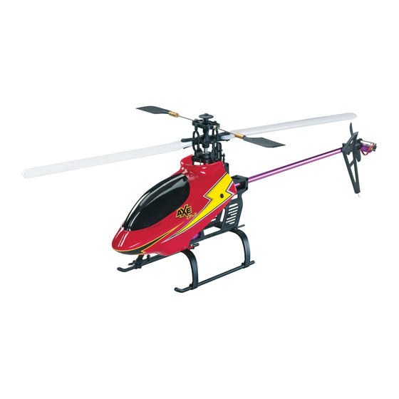
Rotor Span: 20.75 in [528mm]
Height: 8.125 in [206 mm]
Length: 23 in [584mm]
Weight:16 oz [454g]
Motor: 380 Brushed Motor
Radio: 5-Channel FM with 3 Micro Servos,
Receiver, ESC, and Gyro
WARNING!! Read the entire instruction sheet included with this battery and charger. Failure to follow all
instructions could cause permanent damage to the battery, charger or its surroundings, and cause bodily harm!
• Only use a LiPo approved charger. NEVER use a NiCd/
NiMH peak charger!
• Do not attempt to use this charger with NiCd or NiMH
battery packs.
• Never charge in excess of 4.20V per cell.
• Only charge through the "charge" lead. Never charge
through the "discharge" lead.
• Use only the supplied AC wall adapter to power the charger.
• If the battery should become damaged, discard the battery.
Do not attempt to use a damaged battery.
• Do not leave the charger unattended while charging.
Disconnect the battery and remove input power from the
charger immediately if either becomes hot! However, It is
normal for the charger to get warm.
• Disconnect the battery from the charger and carefully move
the battery to a fi reproof location if the battery begins to
swell or smoke!
• Never charge at currents greater than 1C.
• Always charge in a fi reproof location.
READ THROUGH THIS MANUAL BEFORE STARTING CONSTRUCTION.
IT CONTAINS IMPORTANT INSTRUCTIONS AND WARNINGS
CONCERNING THE ASSEMBLY AND USE OF THIS MODEL.
IMPORTANT PRECAUTIONS
• Never trickle charge.
• Never allow the battery temperature to exceed 150° F
[65° C].
• Never disassemble or modify pack wiring in any way or
puncture cells.
• Never discharge below 2.5V per cell.
• Do not allow water, moisture or foreign objects into
the charger.
• Do not block the air intake holes, which could cause the
charger to overheat.
• Do not place the charger or any battery on a fl ammable
surface or near a combustible material while in use.
• Do not charge on a carpet, cluttered workbench, paper,
plastic, vinyl, leather, wood, and inside an R/C model.
• Never charge inside a full sized vehicle.
• Always disconnect the battery from the charger and the
power supply from the charger when not in use.
• Do not attempt to charge a battery if it is swollen or hot.
• ALWAYS KEEP OUT OF REACH OF CHILDREN.
INSTRUCTION MANUAL
Champaign, Illinois
(217) 398-8970
helihotline@hobbico.com
Advertisement
Table of Contents

Related Manuals for Heli-Max AXE CPv3


Summary of Contents for Heli-Max AXE CPv3
- Page 1 Rotor Span: 20.75 in [528mm] Height: 8.125 in [206 mm] Length: 23 in [584mm] Weight:16 oz [454g] Motor: 380 Brushed Motor Radio: 5-Channel FM with 3 Micro Servos, INSTRUCTION MANUAL Receiver, ESC, and Gyro IMPORTANT PRECAUTIONS WARNING!! Read the entire instruction sheet included with this battery and charger. Failure to follow all instructions could cause permanent damage to the battery, charger or its surroundings, and cause bodily harm! •...
-
Page 2: Table Of Contents
• Keep your face and body as well as all spectators away For the latest technical updates or manual corrections from the plane of rotation of the rotors whenever the battery to the AXE CP V3 RTF visit the Heli-Max web site at is connected. www.helimax-rc.com. Open the “Helicopters” link, and then select the AXE CP V3 RTF. -
Page 3: Items Required
fl ight to insure that all equipment is operating and that the model has remained structurally sound. Be sure to check In that Heli-Max has no control over the fi nal assembly linkages or other connectors often and replace them if they or material used for fi... -
Page 4: Kit Contents
KIT CONTENTS 1. Transmitter 4. Helicopter 7. Training Gear (Carbon 2. Main Rotor Blades 5. Charger Rods, Fittings, Foam Balls) 3. Body 6. LiPo Battery 8. DVD BATTERY & CHARGER HMXP1004 3S LiPo CHARGER SPECIFICATIONS GPMP0401 BATTERY SPECIFICATIONS Input voltage: 12V DC Capacity: 950mAh... -
Page 5: Assembly Instructions
CHARGING THE FLIGHT BATTERY ASSEMBLY INSTRUCTIONS IMPORTANT!! Always remove the LiPo battery pack from the helicopter and charge the battery in a location INSTALL BATTERIES IN THE TRANSMITTER that is fi reproof. Never leave the battery unattended while being charged! If the battery becomes hot, starts to smoke or begins to swell immediately disconnect the battery from the charger and carefully move the battery to a fi... - Page 6 that the battery is being charged. If the charger indicator INSTALL MAIN ROTOR BLADES light turns to green immediately, then the battery is already fully charged. ❏ 4. When the battery is fully charged, the charge indicator light will turn GREEN. Remove the battery from the charger at this time and disconnect the charger from its power source.
-
Page 7: Get The Model Ready To Fly
ASSEMBLE TRAINING GEAR GET THE MODEL READY TO FLY ELECTRIC MOTOR WARNING ❏ 1. Snap the four plastic fi ttings onto the landing gear as shown. Slide the carbon rods through the underside of the fi ttings. Electric-powered models are very dangerous. Please remove the pinion gear or unplug the motor while working on the model. -
Page 8: Preflight
transmitter on, you should be able to walk at least 50 feet 5) I will not fl y my model unless it is identifi ed with my name away from the model and still have control. Have an assistant and address or AMA number, on or in the model. Note: stand by your model and while you work the controls, tell you This does not apply to models while being fl... -
Page 9: Controls
Idle Up Switch: Used for forward fl ight and aerobatics. This CONTROLS switch raises the main rotor RPM and also changes the lowest position on the throttle stick to around 40% throttle. This allows the AXE CP V3 RTF to perform aerobatics and inverted fl ight. This can be a dangerous switch since it raises the throttle. - Page 10 Moving the cyclic stick forward (away from you) will cause Moving the tail rotor stick left will cause the helicopter nose the helicopter to tilt forward and start moving that direction. to move left (counterclockwise). Moving the tail rotor stick right will cause the helicopter nose to move right (clockwise).
-
Page 11: Flying
TRACKING THE MAIN BLADES FLYING TAKEOFF During your fi rst fl ights it is important to have light winds and a helper to keep an eye on things around you. Also, if you are fl ying from grass, make sure it’s cut low as this will allow the helicopter to slide around without catching. -
Page 12: Maintenance & Repair
transitions. This will allow you to practice nose-in and still MAINTENANCE & REPAIRS give you a chance to get out of trouble. As you improve you’ll remain nose-in for longer periods of time. Forward Flight: Now it’s time to work into basic forward E-BOARD ADJUSTMENTS fl... - Page 13 SERVO SETUP SPINDLE REPLACEMENT Note: The AXE CP V3 RTF is factory set-up and test fl own so there is no need to make these adjustments unless you have damaged or changed a servo. Servo arms are perfectly level when the throttle stick is all the way down in normal mode (Idle Up Off).
- Page 14 by pulling outward. Remove the dampening spacer. Pull on MAIN SHAFT REMOVAL the other blade grip and remove the spindle and blade grip. If the O-rings come loose, simply press them back into the head block. New spindle installation. Apply threadlocking compound to one of 2mm screws.
-
Page 15: Optional Upgrade
Solder and Soldering Iron Wire Cutters Installing a heading hold gyro into the Heli-Max AXE CP V3 RTF will make the model easier to fl y. The gyro will now allow you to focus your concentration on the other controls instead of constantly fl... - Page 16 Solder a Micro Deans plug onto the motor wires of the C- 12 ESC as shown. The negative (–) motor lead (blue wire) connects to the male pin on the connector. This will be connected to the tail motor in a later step. Disconnect the tail motor plug as shown above and connect the plug directly into the blue and white motor wires on the C-12 ESC.
- Page 17 Since the E-Board provides power to the receiver and servos, On the gyro, set the “AVCS” switch to “ON” and set the “DIR” the BEC in the C-12 ESC must be disabled. Carefully lift up switch to “REV”. Set the gain to 60% using the adjustment the plastic tab on the C-12 ESC connector, remove the red dial on the gyro.
-
Page 18: Ordering Parts
24 HMXE9561 ..Tail Vertical Fin Bracket w/screws ..3 25 HMXE7301 ..Replacement Bearing Set ....8 Replacement parts for the Heli-Max AXE CP V3 RTF are 26 HMXE8405 ..Main Shaft Collar and Bushing ..3 available using the order numbers in the Parts List on page 27 HMXE7627 .. -
Page 19: Exploded View
EXPLODED VIEW DETAILED VIEW OF ROTOR HEAD... -
Page 20: Parts Images
LiPo Battery 1 PC Antenna Tube 1 PC Canopy 1 PC Canopy Grommets 2 PCS 950 mAh 11.1V Part # HMXE4703 Part # HMXE7420 Part # HMXE7426 Part # GPMP0401 EVPL # 5 EVPL # 1 EVPL # 3 EVPL # 4 Center Hub 1 PC 3s LiPo Balance Charger... - Page 21 Screw Set 40 PCS Silicon Secture Tubes 4 PCS Skids 2 PCS Part # HMXE7342 Part # HMXE8701 Part # HMXE8901 EVPL # 8 EVPL# 7 Skid Supports 2 PCS Slide Block 1 PC Stabilizer Control Hub 1 PC Swashplate Assembly 1 SET Part # HMXE8902 Part # HMXE9058...
-
Page 22: Optional Parts
OPTIONAL PARTS CF 3D Vertical Fin w/Hardware (1 Set) CF 3D Horiz Fin w/Hardware (1 Set) CF 3D Flybar Paddles (2 Pcs) Part # HMXE7450 Part # HMXE7451 Part # HMXE7452 CF Tail Boom (1 Set) CNC Swashplate Assembly (1 Set) CNC Center Hub &... - Page 23 LiPo Charger Part # GPMP0401 Part # GPMM3010 ElectriFly Triton2 ™ Charger DuraTrax ® IntelliPeak ™ ™ Charger Part # GPMM3153 Part # DTXP4170 ™ ElectriFly Triton Jr Charger Heli-Max HM4000 Heading Lock Gyro Part # GPMM3152 Part # HMXM1012...
- Page 24 Entire Contents © Copyright 2008 HMXE07xxMNL01...
Need help?
Do you have a question about the AXE CPv3 and is the answer not in the manual?
Questions and answers