Table of Contents
Advertisement
Advertisement
Table of Contents

Subscribe to Our Youtube Channel
Related Manuals for GDC SX-2000


Summary of Contents for GDC SX-2000
- Page 1 GDC Technology Ltd SX-2000 SERVER INSTALLATION MANUAL...
-
Page 2: Table Of Contents
SX-2000 Installation Manual 11/8/2010 Table of Contents Introduction ........................3 SX-2000 and Integrated Media Block (IMB) physical setup ........... 3 Server Presentation ..................... 3 Placing the Server ......................4 Insertion of Drives......................4 Cable connections ......................5 Installing and connecting the GDC Integrated Media Block (IMB) ......... 6 2.5.1... - Page 3 SX-2000 Installation Manual 11/8/2010 3.3.7 Automation setup for Christie ACT devices ............36 3.3.8 Automation setup for Dolby CP650 devices ............37 3.3.9 Automation setup for USL DAX devices .............. 38 3.3.10 Automation setup for USL JSD devices ..............39 3.3.11...
-
Page 4: Introduction
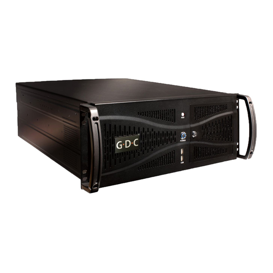
This section describes the physical setup of the SX-2000 server in order to ensure proper operation. 2.1 Server Presentation The front and rear panel of the SX-2000 server is shown in Figure 1 and Figure 2. Figure 1 SX-2000 server front panel Figure 2 SX-2000 server rear panel The SX-2000 can be set up with an external touchscreen LCD, as shown in Figure 3. -
Page 5: Placing The Server
2.2 Placing the Server The SX-2000 is a 4U unit that is designed to be mounted on standard 19” racks. The server is usually mounted to the rack in the projector pedestal, but it can also be mounted to any other standard 19”... -
Page 6: Cable Connections
3. Network connections a. eth0 – Projector b. eth1 – Management 4. USB slot used for connecting to external touch screen monitor 5. PCI-e cable Figure 4 SX-2000 rear panel with cables attached GDC Technology Ltd. Page 5 of 42... -
Page 7: Installing And Connecting The Gdc Integrated Media Block (Imb)
Refer to Section 2.5.2 to connect the PCI-e cable to the IMB on the projector and to the SX-2000 server. If the projector does not have the GDC IMB installed, follow the steps below to install the IMB into the projector. - Page 8 SX-2000 Installation Manual 11/8/2010 Figure 6 GDC Integrated Media Block (IMB) 2.5.1.2 Remove existing interface board/placeholders from projector Before installing the IMB, check the figures below to ensure proper placement of the IMB. Figure 7 shows an interface board (with SMPTE 292 inputs) connected to a Barco projector. This board must be removed in order to install the IMB.
- Page 9 SX-2000 Installation Manual 11/8/2010 installed here Figure 8 IMB placement on Christie projectors Figure 9 shows the location where the IMB should be installed on a NEC projector. Remove any existing interface boards or placeholder faceplates from this position before installing the IMB.
-
Page 10: Connecting The Imb To The Sx-2000 Server
2.5.2 Connecting the IMB to the SX-2000 server The IMB on the projector and the SX-2000 server must be connected for proper operation. There are two cables to be connected between the projector and the SX-2000 server: •... - Page 11 Figure 11 Connecting cables on the projector 2.5.2.2 Connecting to the SX-2000 server Connect the PCI-e cable and the network cables as shown in Figure 12. Figure 12 Connecting cables on the SX-2000 server GDC Technology Ltd. Page 10 of 42...
-
Page 12: Series 2 Projector Setup
SX-2000 Installation Manual 11/8/2010 2.5.3 Series 2 projector setup To work with the GDC IMB, the projector must be set up according to the requirements of the projector manufacturer. 2.5.3.1 Barco Series 2 Projector No system configuration is required for Barco Series 2 projector to work with the GDC IMB. The Service Door/Marriage Tamper on the server must be cleared before the IMB can be used for playback (refer to Section 3.1.2). - Page 13 SX-2000 Installation Manual 11/8/2010 3. Select [Start] ->[Mode] ->[Service] and enter the Service password to activate service mode operation. (See Figure 14) Figure 14 Service mode on NEC Digital Cinema Communicator 4. Select [Setup] ->[Option Slot] on the Digital Cinema Communicator and select IMB for Slot A in Option Slot Setting.
- Page 14 Christie Series 2 Projector When the IMB is installed into a Christie Series 2 projector, the following steps must be taken in order for GDC server to playback with the Christie Series 2 projector: Note: Ensure the projector is powered ON before proceeding.
- Page 15 SX-2000 Installation Manual 11/8/2010 b. Read and perform the actions listed in the Marriage Checklist. In the Marriage Checklist window (see Figure 17), the system checks that all tamper switches are secure and lists items that you must check to ensure the projector is secure before proceeding.
- Page 16 SX-2000 Installation Manual 11/8/2010 Figure 18 Arm Marriage and Marriage countdown d. The Finish window states the success of the marriage. Click the Finish button to return to the Main panel. 2. Clear the Service Door/Marriage Tamper on the server (refer to Section 3.1.2).
- Page 17 SX-2000 Installation Manual 11/8/2010 All 3D IMB channels on the Christie Series 2 projector should use the ‘IMB’ input and ‘4:4:4 (RGB)’ input data format (see Figure 19). Figure 19 Projector input settings for Christie projectors 2.5.3.3.1 3D settings for Christie Series 2 projectors The 3D macros for Christie Series 2 projectors should be configured with the following settings for ‘3D Input Control’...
-
Page 18: Imb 3D Macro Settings Changes
SX-2000 Installation Manual 11/8/2010 Figure 20 3D macro settings for Christie projectors The settings for 3D output control ( ‘3D Sync Polarity’, ‘Dark Time’, ‘Output Delay’ and ‘Phase Delay’) should be customized according to the type of 3D system used (RealD, XpanD or Dolby3D). -
Page 19: Sx-2000 Server Configuration
The ‘IMB 3D 4:4:4’ option in SMS configuration must be checked. No additional configuration is required for the projector. SX-2000 server configuration This section describes the steps necessary to set up the SX-2000 and configure it to work with supported cinema equipment. GDC Technology Ltd. -
Page 20: Sx-2000 Configuration
LED light (SOFT) should be blinking green. 3.1.1 Server IP Setup The IP address of the two network interface cards (NIC) on the SX-2000 server needs to be set for proper operation. When configuring the NICs please keep in mind that eth0 is used for projector communication and eth1 is used for the media network. -
Page 21: Imb And Projector Ip Setup
3.1.2 IMB and Projector IP Setup The IMB and projector IP settings on the SX-2000 server must be configured for proper operation. Once the SX-2000 server IP addresses are set up, the projector IP and IMB marriage can be configured with the following steps: Click the power button once to access the Control Panel Select SMS->Configuration... -
Page 22: Content Ingest Management Setup
SX-2000 Installation Manual 11/8/2010 Figure 24 Cinecanvas setup screen Enter the projector IP address in the “Primary Projector IP” field and enable CineCanvas by checking the box “Enable CineCanvas”. Select General -> IMB to check the Marriage/Service door tamper. Click Clear to clear... - Page 23 SX-2000 Installation Manual 11/8/2010 3.1.3.1 Content ingest from USB disk The following steps describe the setup of a content ingest source for ingesting content from an external USB hard drive: 1. Click the power button once to access the Control Panel.
- Page 24 SX-2000 Installation Manual 11/8/2010 Figure 27 USB ingest source setup 5. Click [Save] to save the settings for the USB content ingest source. 3.1.3.2 Content ingest from FTP The following steps describe the setup of a content ingest source for ingesting content from an FTP server: 1.
- Page 25 SX-2000 Installation Manual 11/8/2010 3. Enter the respective parameters for Source IP, Source Path, Username and Password (see Figure 28). 4. Click [Save] to save the settings for the FTP content ingest source. GDC Technology Ltd. Page 24 of 42...
- Page 26 SX-2000 Installation Manual 11/8/2010 3.1.3.3 Selecting an ingest source To select an ingest source, click next to the “Source to ingest from:” label on the “Ingest” tab. Choose the required ingest source from the drop down menu. (See Figure 29) Figure 29 Ingest from USB source GDC Technology Ltd.
-
Page 27: Time Zone Setup
11/8/2010 3.1.4 Time Zone Setup The SX-2000 server may or may not arrive with the local time zone set. The following steps show how to change the time zone on the server. 1. Click the power button once to access the Control Panel. -
Page 28: Audio Setup
SX-2000 Installation Manual 11/8/2010 3.2 Audio Setup Not every case will require a Digital-to-Analog Converter (DAC) as some sound processors are able to receive digital input. In the case that a DAC is required the first thing that should be done is to connect the server to the DAC. -
Page 29: Dolby Cp650 Sound Processor
SX-2000 Installation Manual 11/8/2010 2. Connect the other end of the audio cable into the input labeled “4x AES In (Digital 8 ch)” on the Dolby DMA8. 3.2.5 Dolby CP650 Sound Processor The Dolby CP650 requires an optional board to be used (650-OPTIO-AES). Once installed the optional 650 OPTIO-AES board will enable 25-pin D-Sub digital input to the Dolby CP650. -
Page 30: Automation Setup
SX-2000 Installation Manual 11/8/2010 3.3 Automation Setup The SX-2000 server is able to control external devices using its automation interface. This can be used to automate repetitive tasks for the cinema operator to prevent user error. 3.3.1 General automation setup The following steps describe the general setup of an automation device on the SX-2000 server. - Page 31 SX-2000 Installation Manual 11/8/2010 3.3.2 Adding event labels and actions The following steps describe how to add an event label to the automation interface. This automation label is used to trigger the associated automation actions during playback. 1. Click the [Add] button next to the ‘Event Label’ menu to add a new event label. Enter the name of the event label.
-
Page 32: Automation Scheduling
3.3.4 Automation setup for server GPIO If the SX-2000 server has a GPIO card installed, the ‘GPIO’ automation device will be available for configuration. It is not possible to add a ‘GPIO’ automation device if the GPIO card is not installed. -
Page 33: Automation Setup For Projectors
Click the [Save] button to save any changes made. 3.3.5 Automation setup for projectors The SX-2000 server supports automation for Barco, Christie and NEC projectors. Follow the steps below to configure a projector device in the server automation interface. 1. Click the [Add] button on the [Devices] tab and enter the name of the device. In this case, it is “PROJECTOR”. -
Page 34: Automation Setup For Ecna Devices
Figure 35 Automation settings for projector device 3.3.6 Automation setup for eCNA devices The SX-2000 server supports the eCNA-10 automation system. Follow the steps below to configure an eCNA device in the server automation interface. 7. Click the [Add] button on the [Devices] tab and enter the name of the device. In this case, it is “eCNA”. - Page 35 SX-2000 Installation Manual 11/8/2010 Figure 36 eCNA automation device setup 8. Click [OK] and set up the device parameters for the eCNA device. 9. Enter the IP address of the eCNA device (see Figure 37). 10. The eCNA device has many cues available for automation. These cues can be enabled or disabled by selecting them after clicking the [Server events], [eCNA controls], and [eCNA status] buttons.
-
Page 36: Automation Setup For Jnior Devices
11/8/2010 3.3.7 Automation setup for JNIOR devices The SX-2000 server supports the JNIOR Model 310 automation device. Follow the steps below to configure a JNIOR device in the server automation interface. 1. Click the [Add] button on the [Devices] tab and enter the name of the device. In this case, it is “JNIOR”. -
Page 37: Automation Setup For Christie Act Devices
Figure 39 Automation settings for JNIOR device 3.3.8 Automation setup for Christie ACT devices The SX-2000 server supports Christie ACT automation device. Follow the steps below to configure a Christie ACT device in the server automation interface. 1. Click the [Add] button on the [Devices] tab and enter the name of the device. In this case, it is “ChristieACT”. -
Page 38: Automation Setup For Dolby Cp650 Devices
Figure 41 Automation settings for Christie ACT device 3.3.9 Automation setup for Dolby CP650 devices The SX-2000 server supports automation for the Dolby CP650 sound processor. Follow the steps below to configure a Dolby CP650 device in the server automation interface. -
Page 39: Automation Setup For Usl Dax Devices
3.3.10 Automation setup for USL DAX devices The SX-2000 server supports automation for USL DAX sound processor. Follow the steps below to configure a USL DAX device in the server automation interface. 1. Click the [Add] button on the [Devices] tab and enter the name of the device. In this case, it is “DAX”. -
Page 40: Automation Setup For Usl Jsd Devices
3.3.11 Automation setup for USL JSD devices The SX-2000 server supports automation for USL JSD-80 and JSD-100 sound processor. Follow the steps below to configure a USL JSD device in the server automation interface. 1. Click the [Add] button on the [Devices] tab and enter the name of the device. In this case, it is “JSD”. -
Page 41: Component Engineering Ta-10 Setup
Figure 47 Automation settings for USL JSD device 3.3.12 Component Engineering TA-10 Setup The Component Engineering TA-10 can be used for theater automation with the SX-2000 server. It requires that the TA-10 be wired in a particular configuration. A wiring diagram can be seen in Figure 48. -
Page 42: Testing Procedures For Qc After Installation
3.4 Testing Procedures for QC after Installation After the installation has been completed, it is necessary to test the following to ensure that the SX-2000 has been properly installed: 1. Test the video playback capabilities of the server using the following file formats: MPEG2, JPEG2000, Scope, Flat, 3D.
Need help?
Do you have a question about the SX-2000 and is the answer not in the manual?
Questions and answers