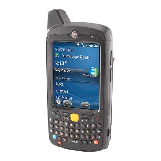
Motorola MC65 Manual
Mobile computer
Hide thumbs
Also See for MC65:
- Quick start manual (2 pages) ,
- User manual (214 pages) ,
- User manual (60 pages)
Table of Contents
Advertisement
Quick Links
Advertisement
Table of Contents
Troubleshooting

Related Manuals for Motorola MC65


Summary of Contents for Motorola MC65
- Page 1 MC65 Integrator Guide...
- Page 3 MC65 Integrator Guide 72E-142435-01 Rev. A September 2010...
- Page 4 Motorola. No right to copy a licensed program in whole or in part is granted, except as permitted under copyright law. The user shall not modify, merge, or incorporate any form or portion of a licensed program with other program material, create a derivative work from a licensed program, or use a licensed program in a network without written permission from Motorola.
-
Page 5: Revision History
Revision History Changes to the original manual are listed below: Change Date Description -01 Rev. A 09/2010 Initial release. - Page 6 MC65 Integrator Guide...
-
Page 7: Table Of Contents
Charging the Battery ........................1-5 Charging the Main Battery ....................... 1-5 Charging Spare Batteries ......................1-6 Charging Temperature ......................1-6 Powering On the MC65 ........................1-6 Calibrating the Screen ......................1-6 First-time Network Activation ......................1-7 Network Activation ........................1-7 Replacing the Battery .......................... - Page 8 Chapter 2: Accessories Introduction ............................2-1 Single Slot USB Cradle ........................2-3 Setup .............................. 2-3 Charging the MC65 Battery ......................2-3 Charging the Spare Battery ......................2-4 Battery Charging Indicators ......................2-4 Charging Temperature ......................2-5 Four Slot Ethernet Cradle ........................2-6 Setup ..............................
- Page 9 Introduction ............................3-1 Installing ActiveSync ..........................3-1 MC65 Setup ............................3-2 Setting Up an ActiveSync Connection on the Host Computer ............. 3-3 Synchronization the MC65 ......................3-3 Chapter 4: Application Deployment Introduction ............................4-1 Security ..............................4-1 Application Security ........................4-1 Digital Signatures ...........................
- Page 10 Magnetic Stripe Reader ......................... 6-11 Appendix A: Technical Specifications MC65 Technical Specifications ......................A-1 MC65 ............................. A-1 MC65 External Connector Pin-Outs ....................A-6 MC65 Accessory Specifications ......................A-7 Single Slot USB Cradle ........................A-7 Single Slot Ethernet/Modem/USB Cradle ..................A-8 Four Slot Battery Charger ......................
- Page 11 Table of Contents Four Slot Ethernet Cradle ......................A-9 Magstripe Reader .......................... A-10 Vehicle Cradle ..........................A-11 Cables ............................A-11 Glossary Index...
- Page 12 MC65 Integrator Guide...
-
Page 13: About This Guide
Screens and windows pictured in this guide are samples and can differ from actual screens. Documentation Set The documentation for the MC65 is divided into guides that provide information for specific user needs. • MC65 Quick Start Guide - describes how to get the MC65 up and running. -
Page 14: Software Versions
MC65 configurations and accessories, charging the battery, and resetting the device. • Chapter 2, Accessories describes the accessories available for the MC65 and how to set up power connections and battery charging capabilities, where applicable. • Chapter 3, ActiveSync provides instructions on installing ActiveSync and setting up a partnership between the MC65 and a host computer. -
Page 15: Notational Conventions
Wireless Fusion Enterprise Mobility Suite User Guide for Version 3.20, p/n 72E-113153-01. • Enterprise Mobility Developer Kits (EMDKs), available at: http://www.motorola.com/enterprisemobility/support. • Latest ActiveSync software, available at: http://www.microsoft.com. For the latest version of this guide and all guides, go to: http://www.motorola.com/enterprisemobility/manuals. -
Page 16: Service Information
Software type and version number. Manufacturing label Motorola responds to calls by e-mail, telephone or fax within the time limits set forth in support agreements. If your problem cannot be solved by Motorola Enterprise Mobility Support, you may need to return your equipment for servicing and will be given specific directions. -
Page 17: Introduction
Chapter 1 Getting Started Introduction This chapter lists the parts and accessories for the MC65 and explains how to set up the MC65 for the first time. Unpacking Carefully remove all protective material from the MC65 and save the shipping container for later storage and shipping. -
Page 18: Installing A Microsd Card
1 - 2 MC65 Integrator Guide Getting Started To start using the MC65 for the first time: • Install a microSD card (optional) • Install the SIM card (GSM only) • Install the main battery pack. • Charge the MC65. -
Page 19: Installing The Sim Card
GSM only. NOTE GSM phone service requires a Subscriber Identification Module (SIM) card. Obtain the card from the your service provider. The card fits into the MC65 and can contain the following information: • Mobile phone service provider account details. -
Page 20: Installing The Battery
Close SIM card holder door and slide down to lock into place. Close the rubber access door. Install the battery. NOTE For detailed information about WWAN activation and settings, refer to the MC65 Integrator Guide. Installing the Battery To install the battery. -
Page 21: Charging The Battery
The MC65 is equipped with a memory backup battery which automatically charges from the fully-charged main battery. When using the MC65 for the first time, the backup battery requires approximately 40 hours to fully charge. This is also true any time the backup battery is discharged, which occurs when the main battery is removed for several hours. -
Page 22: Charging Spare Batteries
Table 1-1. Powering On the MC65 Press the Power button to turn on the MC65. The splash screen displays for about a minute as the MC65 initializes its flash file system, then the calibration window appears. Calibrating the Screen NOTE The Calibration screen can be accessed by pressing Blue key then Backspace key. -
Page 23: First-Time Network Activation
Getting Started 1 - 7 First-time Network Activation Network Activation To activate on a GSM/UMTS network: If an active SIM card was installed in the ES400, the ES400 performs the activation process. The Phone Network - GSM/UMTS Setup dialog box displays. Tap Yes and then OK. -
Page 24: Replacing The Battery
Press the battery down until the battery release latch snaps into place. Replace the handstrap. Resetting the MC65 A reset restarts the MC65 by closing all running programs. Data saved in flash memory or a memory card is not lost. If the MC65 is not functioning properly, perform a reset. -
Page 25: Performing A Clean Boot
Calibrate the screen. Waking the MC65 The wake-up conditions define what actions wake up the MC65 after it has gone into suspend mode. The MC65 can go into suspend mode by either pressing the Power button or automatically by time-out settings... - Page 26 1 - 10 MC65 Integrator Guide...
-
Page 27: Chapter 2 Accessories
Chapter 2 Accessories Introduction This chapter provides set up information for the MC65 various accessories listed in Table 2-1: MC65 Accessories Table 2-1 Accessory Part Number Description Cradles Single Slot USB Cradle CRD5500-1000UR Charges the MC65 main battery and a spare battery. Synchronizes the MC65 with a host computer through a USB connection. - Page 28 Magnetic Stripe Reader MSR5500-100R Captures data from magnetic stripe cards. Belt Mounted Rigid Holster SG-MC5511110-01R Clips onto belt to hold the MC65 when not in use. Fabric Holster SG-MC5521110-01R Soft holder for added protection. Stylus KT-119150-03R Replacement stylus (3-pack).
-
Page 29: Single Slot Usb Cradle
Accessories 2 - 3 Single Slot USB Cradle This section describes how to set up and use a Single Slot USB cradle with the MC65. For USB communication setup procedures see Chapter 3, ActiveSync. The Single Slot USB cradle: •... -
Page 30: Charging The Spare Battery
Charge Status LED MC65 Battery Charging Figure 2-2 Charging the Spare Battery Spare Battery Spare Battery Charging LED Spare Battery Charging Figure 2-3 Battery Charging Indicators The Single Slot USB cradle charges the MC65’s main battery and a spare battery simultaneously. -
Page 31: Charging Temperature
Charge batteries in temperatures from 0°C to 40°C (32°F to 104°F). Charging is intelligently controlled by the MC65. To accomplish this, for small periods of time, the MC65 or accessory alternately enables and disables battery charging to keep the battery at acceptable temperatures. The MC65 or accessory indicates when charging is disabled due to abnormal temperatures via its LED. -
Page 32: Four Slot Ethernet Cradle
2 - 6 MC65 Integrator Guide Four Slot Ethernet Cradle This section describes how to set up and use a Four Slot Ethernet cradle with the MC65. The Four Slot Ethernet cradle: • Provides 5.4 VDC power for operating the MC65. -
Page 33: Ethernet Cradle Drivers
Daisychaining Four Slot Ethernet Cradles Figure 2-5 Ethernet Cradle Drivers The MC65 includes Ethernet cradle drivers that initiate automatically when you place the MC65 in a properly connected Four Slot Ethernet cradle. After inserting the MC65, configure the Ethernet connection: >... - Page 34 2 - 8 MC65 Integrator Guide IP Address Tab Figure 2-7 In the window, select the appropriate radio button: IP address • Use server-assigned IP address • . Enter the IP address, Subnet mask, and Default gateway, as needed. Use specific IP address Tap the tab.
-
Page 35: Charging And Communication
Charge batteries in temperatures from 0°C to 40°C (32°F to 104°F). Charging is intelligently controlled by the MC65. To accomplish this, for small periods of time, the MC65 alternately enables and disables battery charging to keep the battery at acceptable temperatures. The MC65 indicates when charging is disabled due to abnormal temperatures via its LED. -
Page 36: Four Slot Charge Only Cradle
2 - 10 MC65 Integrator Guide Four Slot Charge Only Cradle This section describes how to set up and use a Four Slot Charge Only cradle with the MC65. The Four Slot Charge Only cradle: • Provides 5.4 VDC power for operating the MC65. -
Page 37: Wall Mount Bracket
Accessories 2 - 11 Wall Mount Bracket Use the optional Wall Mount Bracket to mount a four slot cradle to a wall. To attach the Wall Mount Bracket: Use the Wall Mount Bracket as a template and mark the locations of the four mounting screws. NOTE Use fasteners appropriate for the type of wall and the Wall Mount Bracket mounting slots. - Page 38 2 - 12 MC65 Integrator Guide Swing the four slot cradle down onto the mounting bracket and align the mounting screws so that they fit into the screw slots. Wall Mount Bracket Screw Slots Power Supply Well Wall Mount Bracket Figure 2-13 Tighten the mounting screws to secure the four slot cradle to the bracket.
-
Page 39: Vcd5500 Vehicle Cradle
CAUTION with the MC65 display facing up. Never mount the vehicle cradle on the side or upside down or on a wall that can be subject to impact or collision of greater than 40Gs, in accordance with SAE J1455 Section 4.10.3.5... -
Page 40: Power Connection
Select a mounting location for the cradle. It should be flat, and must provide adequate support for the cradle. NOTE If using the GPS functionality of the MC65, ensure that the vehicle cradle is positioned so that the MC65 has a clear unobstructed view of the sky. - Page 41 Connect the power input cable into the power port on the cradle. To see if the cradle has power, insert the MC65. The Charging LED on the MC65 blinks slowly to indicate charging and turns solid amber when the battery is completely charged. See Table 1-1 on page 1-6 for other indications.
-
Page 42: Charging The Mc65 Battery
Motorola, Inc. is not responsible for any loss resulting from the use of the products while driving. Removing the MC65 To remove the MC65, press the release levers on the cradle and pull the MC65 up and out of the cradle. Release Lever Removing the MC65... -
Page 43: Battery Charging Indicators
Charge batteries in temperatures from 0°C to 40°C (32°F to 104°F). Charging is intelligently controlled by the MC65. To accomplish this, for small periods of time, the MC65 alternately enables and disables battery charging to keep the battery at acceptable temperatures. The MC65 indicates when charging is disabled due to abnormal temperatures via its LED. -
Page 44: Four Slot Battery Charger
2 - 18 MC65 Integrator Guide Four Slot Battery Charger This section describes how to use the Four Slot Battery Charger to charge up to four MC65 spare batteries. Spare Battery Charging Connect the charger to a power source. Insert the spare battery into a spare battery charging well and gently press down on the battery to ensure proper contact. - Page 45 Accessories 2 - 19 Spare Battery LED Charging Indicators Table 2-4 Indication No spare battery in slot; spare battery not placed correctly; cradle is not powered. Fast Blinking Amber Error in charging; check placement of spare battery. Slow Blinking Amber Spare battery is charging.
-
Page 46: Cables
Auto Charge cable. USB Charging Cable The USB Charging cable provides the MC65 with operating and charging power when used with the Motorola approved power supply and AC line cord and synchronize information between the MC65 and a host computer. -
Page 47: Auto Charge Cable
If required, connect the cable power input connector to the Motorola approved power source. Slide the bottom of the MC65 into the connector cup end of the cable until the MC65 is firmly seated in the cup. Slide the two locking tabs up until they both lock into position. -
Page 48: Battery Charging Indicators
To remove, slide the two locking tab down and remove the cable from the MC65. Battery Charging Indicators The MC65 amber Charge LED indicates the MC65 battery charging status. The 3600 mAh battery charges in less than six hours. See Table 1-1 on page 1-6 for charging status indications. - Page 49 Accessories 2 - 23 To accomplish this, for small periods of time, the MC65 alternately enables and disables battery charging to keep the battery at acceptable temperatures. The MC65 indicates when charging is disabled due to abnormal temperatures via its LED. See Table 1-1 on page 1-6.
-
Page 50: Vehicle Holder
Do not mount the vehicle holder near the driver seat air bag deployment area. • Do not place the MC65 on top of the dashboard or anywhere without securing it in the vehicle holder. • Do not mount the vehicle holder near the passenger seat air bag deployment area. -
Page 51: Assembly
Windshield Installation Figure 2-25 Flip the lever down to create a vacuum between the suction cup and the mounting surface. Make sure that the suction bond is strong enough before proceeding to the next step. Slide the MC65 into the cradle. -
Page 52: Flat Surface Installation
Locking Tab Insert MC65 into Vehicle Holder Figure 2-26 Connect the auto charger cable to the MC65 and slide the two locking tabs up to secure the cable cup to the MC65. Connect the other end to the cigarette lighter socket. - Page 53 Vehicle Holder Mounted on Flat Surface Figure 2-28 Connect the auto charger cable to the MC65 and slide the two locking tabs up to secure the cable cup to the MC65. Connect the other end to the cigarette lighter socket.
- Page 54 2 - 28 MC65 Integrator Guide...
-
Page 55: Chapter 3 Activesync
Changes made on the MC65 or host computer appear in both places after synchronization. NOTE When an MC65 with Windows Mobile 6.5 is connected to a host computer and an ActiveSync connection is made, the WLAN radio (if applicable) is disabled. This is a Microsoft security feature to prevent connection to two networks at the same time. -
Page 56: Mc65 Setup
The MC65 by default is set up to communicate through a USB connection. Chapter 2, Accessories provides the accessory setup and cable connection information for use with the MC65. The MC65 communication settings must be set to match the communication settings used with ActiveSync. On the MC65 tap >... -
Page 57: Setting Up An Activesync Connection On The Host Computer
Start Programs Microsoft ActiveSync ActiveSync ActiveSync Window Figure 3-1 NOTE Assign each MC65 a unique device name. Do not try to synchronize more than one MC65 to the same name. In the window, select > . The window appears. ActiveSync... - Page 58 3 - 4 MC65 Integrator Guide To synchronize: If the window does not appear on the host computer, select > > Get Connected Start All Programs Microsoft ActiveSync Synchronization Setup Wizard Window Figure 3-3 Click Next Synchronization Directly With a Server Window Figure 3-4 Select the check box to synchronize with a server running Microsoft Exchange if applicable.
- Page 59 ActiveSync 3 - 5 Synchronization Option Window Figure 3-5 Select the appropriate settings and click Next Wizard Complete Window Figure 3-6 Click Finish ActiveSync Connected Window Figure 3-7...
- Page 60 3 - 6 MC65 Integrator Guide During the first synchronization, information stored on the MC65 is copied to the host computer. When the copy is complete and all data is synchronized, the MC65 can be disconnect from the host computer.
-
Page 61: Chapter 4 Application Deployment
MC65. Security The MC65 implements a set of security policies that determine whether an application is allowed to run and, if allowed, with what level of trust. To develop an application, you must know the security configuration of the device, and how to sign an application with the appropriate certificate to allow the application to run (and to run with the needed level of trust). -
Page 62: Locking Down A Mobile Computer
4 - 2 MC65 Integrator Guide This means that only applications signed with a certificate from the Privileged Execution Trust Certificate Store can run. To support the broadest number of deployments, third-party software developers should perform the following when releasing software for a Windows Mobile 6 devices: •... -
Page 63: Installing Certificates
The Remote API (RAPI) enables applications that run on a desktop to perform actions on a remote device. RAPI provides the ability to manipulate the file system on the remote device, including the creation and deletion of files and directories. By default, Motorola ships with RAPI in the restricted mode. Certain tools, such as RAPIConfig,... -
Page 64: Packaging
Packaging combines an application's executable files into a single file, called a package. This makes it easier to deploy and install an application to the MC65. Package new applications and updates, such as new DLL files, as CAB files, then deploy them to devices. Refer to the Microsoft Windows Mobile 6 Help file for information on CAB files. -
Page 65: Installation Using Airbeam
Refer to the AirBEAM Smart Windows CE Client Product Reference Guide, p/n 72-63060-xx, for instructions for AirBEAM Smart client. The MSP 3 Client Software is a set of software components that come pre-installed on the MC65. The MSP 3 Client software consists of the following components: The RD Client provides support for MSP 3 Staging functionality, provides support for the MSP 3 Legacy Staging process, and provides support for backward-compatible legacy MSP 2.x Legacy Staging functionality. -
Page 66: Microsd Card
The Update Loader application looks for the update loader file in the root directory of the microSD card. When it finds the file, it loads the update loader package onto the MC65. A progress bar displays until the update completes. -
Page 67: Xml Provisioning Vs. Regmerge And Copy File
Optionally, use the Authenticode tools to sign the .cpf file. Tap the filename to install. Certain applications and settings require a cold boot to take affect. In these cases, cold boot the MC65. Refer to the Windows Mobile Version 6 Help file for more information. -
Page 68: Storage
The MC65 uses the Cache Disk for temporary data that can be restored from other sources, for example, for temporarily “caching” HTML web pages by a browser or generating formatted files to send to a printer. Both... -
Page 69: Persistent Storage
Windows Mobile 6 protects all data and applications from power-related loss. Because Windows Mobile 6 mounts the entire file system and registry in persistent storage (rather than using RAM), MC65 devices provide a reliable storage platform even in the absence of battery power. - Page 70 4 - 10 MC65 Integrator Guide...
-
Page 71: Chapter 5 Phone Setup
MC65 upon startup. Manual Network Setup NOTE When an AT&T SIM card is installed in the MC65, the user interface for the CDMA settings is hidden. To restore access to these settings, please contact Motorola Enterprise Mobility Support. -
Page 72: Gsm Network Setup
Tap Start Activation button. On the Phone Network - CDMA Activation dialog box, tap Yes. On an active phone line, call your carrier to active the MC65. Provide the MEID number on the screen to the customer representative. When requested, tap Activate Now to activate the MC65. -
Page 73: Dual Network Usage
Phone Setup 5 - 3 Dual Network Usage The MC65 can be set up to be used on both a CDMA and GSM/UMTS networks and the user can switch between them. NOTE Each active network account uses its own phone number. - Page 74 5 - 4 MC65 Integrator Guide Tap > Start > Setting > Connections > Phone network Setup. On the Band tab, tap Network type and select CDMA First or CDMA Only. Tap OK.
-
Page 75: Configuring A Gsm Data Connection
Phone Setup 5 - 5 Configuring a GSM Data Connection NOTE SIM cards of supported carriers automatically configure the data connection upon activation. Data connections for non-supported carriers must be manually configured. A data connection allows Internet access across a wireless network. To set up a new data connection: Acquire an Access Point Name (APN) from the service provider. -
Page 76: Phone Settings
The ring type changes the way the MC65 rings when it Ring type: receives an incoming call. Regardless of the ring type selected, a dialog box appears on the MC65’s display for incoming calls. Select a ring tone for incoming calls from the drop-down list. -
Page 77: Changing A Pin
Phone Setup 5 - 7 Security Tab Figure 5-2 To require a PIN when using the phone: Select the check box. Require PIN when phone is used Enter PIN Figure 5-3 Use the dialer keypad to enter a four to eight digit PIN. to enable the PIN and return to the tab. -
Page 78: Disabling A Pin
5 - 8 MC65 Integrator Guide to confirm the change. Disabling a PIN Deselect the check box. Require PIN when phone is used Use the dialer keypad to enter the current PIN. Enter to confirm the change and exit settings. -
Page 79: Call Waiting
Done NOTE PIN2 is buffered in the MC65 indefinitely after entry and will not be requested again until a reboot of the MC65 has been performed. Should PIN2 be required, then the user must perform a reboot of the MC65. -
Page 80: Internet
5 - 10 MC65 Integrator Guide Internet Use the Internet tab to configure Internet calling. Broadcast Channels Enable broadcast messages from local cell sites. These messages include emergency directions and information services. -
Page 81: Chapter 6 Maintenance & Troubleshooting
Do not store or use the MC65 in any location that is dusty, damp, or wet. • Use a soft lens cloth to clean the MC65. If the surface of the MC65 screen becomes soiled, clean it with a soft cloth moistened with a diluted window-cleaning solution. -
Page 82: Removing The Screen Protector
• Quick and easy installation. Removing the Screen Protector A screen protector is applied to the MC65. Motorola recommends using this to minimize wear and tear. Screen protectors enhance the usability and durability of touch screen displays. To remove the screen protector, lift the corner using a thin plastic card, such as a credit card, then carefully lift it off the display. -
Page 83: Cleaning
Always wear eye protection. Read warning label on compressed air and alcohol product before using. If you have to use any other solution for medical reasons please contact Motorola for more information. WARNING Avoid exposing this product to contact with hot oil or other flammable liquids. If such exposure occurs, unplug the device and clean the product immediately in accordance with these guidelines. -
Page 84: Cleaning The Mc65
Dip the cotton portion of the cotton tipped applicator in isopropyl alcohol. Rub the cotton portion of the cotton tipped applicator back-and-forth across the connector on the bottom of the MC65. Do not leave any cotton residue on the connector. Repeat at least three times. -
Page 85: Cleaning Frequency
Replace battery. If the MC65 still does not operate, perform a did not charge. reset. See Resetting the MC65 on page 1-8. MC65 removed Insert MC65 in cradle. The 3600 mAh battery fully charges in less from cradle while than six hours. battery was charging. Extreme battery Battery does not charge if ambient temperature is below 0°C... - Page 86 MC65 shuts off. MC65 is inactive. The MC65 turns off after a period of inactivity. If the MC65 is running on battery power, set this period from 1 to 5 minutes, in one-minute intervals. Check the Power window by selecting Tap Status Bar >...
-
Page 87: Bluetooth Connection
Refer to the EMDK or Control Panel application. bar code. MC65 is not If the MC65 does not beep on a good decode, set the application programmed to to generate a beep on good decode. generate a beep. -
Page 88: Single Slot Usb Cradle
AC power. battery is inserted. MC65 is not seated Remove and re-insert the MC65 into the cradle, ensuring it is firmly firmly in the cradle. seated. Spare battery is not Remove and re-insert the spare battery into the charging slot, seated firmly in the ensuring it is firmly seated. -
Page 89: Four Slot Ethernet Cradle
An icon is visible in the status bar if a connection is currently active. incomplete. connection. Battery is not MC65 removed Replace the MC65 in the cradle. The 3600 mAh battery fully charging. from the cradle too charges in less than six hours. Tap Status Bar > to view battery soon. -
Page 90: Four Slot Battery Charger
Battery is faulty. Verify that other batteries charge properly. If so, replace the faulty battery. The MC65 is not Detach and re-attach the power cable to the MC65, ensuring it is fully attached to firmly connected. power. During data Cable was Re-attach the cable and retransmit. -
Page 91: Magnetic Stripe Reader
Battery is faulty. Verify that other batteries charge properly. If so, replace the faulty battery. The MC65 is not Detach and re-attach the MSR to the MC65, ensuring it is firmly fully attached to the connected. MSR. During data MC65 detached Reattach MC65 to MSR and retransmit. - Page 92 6 - 12 MC65 Integrator Guide...
-
Page 93: Appendix A Technical Specifications
Appendix A Technical Specifications MC65 Technical Specifications The following tables summarize the EDA’s intended operating environment and technical hardware specifications. MC65 MC65 EDA Technical Specifications Table A-1 Item Description Physical Characteristics Dimensions Height: 16.2 cm (6.38 in.) Width: 7.7 cm (3.03 in.) Depth: 3.4 cm (1.32 in.) - Page 94 A - 2 MC65 Integrator Guide MC65 EDA Technical Specifications (Continued) Table A-1 Item Description Performance Characteristics MSM Qualcomm 7627@ 600 MHz (multi-processor architecture) Operating System ® Microsoft Windows Mobile™ 6.5 Professional Memory 256 MB RAM/1 GB Flash Output Power USB: 5 VDC @ 300 mA max.
- Page 95 MS-CHAPv2, PAP or MD5); PEAP (TLS, MSCHAPv2, EAP-GTC); LEAP, EAP-FAST (TLS, MS-CHAPv2, EAP-GTC) Voice Communications Voice-over-IP ready, Wi-Fi™-certified, IEEE 802.11a/b/g direct sequence wireless LAN, Wi-Fi Multimedia™ (WMM and WMM-PS) Motorola Voice Quality Manager (VQM), Motorola TEAM Express Ready Wireless PAN Data and Voice Communications Bluetooth Class II, v2.0 with Enhanced Data Rate (EDR)
- Page 96 A - 4 MC65 Integrator Guide MC65 EDA Technical Specifications (Continued) Table A-1 Item Description Wireless Wide Area Network GSM-HSDPA Global: 3GPP TS 51.010, 3GPP TS 34.121, 3GPP TS 34.123, GCF and PTCRB approved USA: FCC Part 22, Part 24...
- Page 97 Technical Specifications A - 5 MC65 EDA Technical Specifications (Continued) Table A-1 Item Description Illumination Element (LED) 625 nm +/- 5 nm Camera Specifications Resolution 3.2 Mega pixel Data Capture Options Table A-2 Item Description Laser Decode Capability Code 39...
-
Page 98: Mc65 External Connector Pin-Outs
GS1 DataBar GS1 DataBar Truncated GS1 DataBar Limited GS1 DataBar Stacked GS1 DataBar Expanded GS1 DataBar Expanded Stacked GS1 DataBar Stacked Omni MC65 External Connector Pin-Outs Pin 1 External Connector Figure A-1 External Connector Pin-Outs Table A-3 Description External Trigger/Cradle Detect USB_ID 5.4 VDC... -
Page 99: Mc65 Accessory Specifications
Technical Specifications A - 7 External Connector Pin-Outs (Continued) Table A-3 Description USB_D- USB_D+ Ground MC65 Accessory Specifications Single Slot USB Cradle Single Slot USB Cradle Technical Specifications Table A-4 Feature Description Dimensions Height: 7.1 cm (2.80 in.) Width: 11.0 cm (4.33 in.) Depth: 15.0 cm (5.91 in.) -
Page 100: Single Slot Ethernet/Modem/Usb Cradle
A - 8 MC65 Integrator Guide Single Slot Ethernet/Modem/USB Cradle Single Slot Ethernet/Modem/USB Cradle Technical Specifications Table A-5 Feature Description Dimensions Height: 7.1 cm (2.80 in.) Width: 11.0 cm (4.33 in.) Depth: 15.0 cm (5.91 in.) Weight 210 g (7.41 oz) -
Page 101: Four Slot Charge Only Cradle
Technical Specifications A - 9 Four Slot Battery Charger Technical Specifications (Continued) Table A-6 Feature Description Humidity 5% to 95% non-condensing Drop 76.2 cm (30.0 in.) drops to vinyl tiled concrete at room temperature Electrostatic Discharge (ESD) +/- 15 kV air +/- 8 kV contact Four Slot Charge Only Cradle Four Slot Charge Only Cradle Technical Specifications... -
Page 102: Magstripe Reader
A - 10 MC65 Integrator Guide Four Slot Ethernet Cradle Technical Specifications (Continued) Table A-8 Feature Description Storage Temperature -40°C to 70°C (-40°F to 158°F) Charging Temperature 0°C to 40°C (32°F to 104°F) Humidity 5% to 95% non-condensing Drop 76.2 cm (30.0 in.) drops to vinyl tiled concrete at room temperature... -
Page 103: Vehicle Cradle
Technical Specifications A - 11 Vehicle Cradle Vehicle Cradle Technical Specifications Table A-10 Feature Description Dimensions Height: 10.4 cm (4.09 in.) Width: 11.1 cm (4.37 in.) Depth: 6.9 cm (2.72 in.) Weight 240 g (8.47 oz) Power 9- 32 VDC Operating Temperature -20°C to 50°C (-4°F to 122°F) Storage Temperature... - Page 104 A - 12 MC65 Integrator Guide Charge Only Cable Technical Specifications (Continued) Table A-12 Feature Description Storage Temperature -40°C to 70°C (-40°F to 158°F) Humidity 10% to 95% non-condensing Electrostatic Discharge (ESD) +/- 15 kV air +/- 8 kV contact...
-
Page 105: Glossary
Glossary API. (Application Programming Interface) An interface by means of which one software component communicates with or controls another. Usually used to refer to services provided by one software component to another, usually via software interrupts or function calls AZERTY. A standard keyboard commonly used on French keyboards. “AZERTY” refers to the arrangement of keys on the top row of keys. - Page 106 Glossary - 2 MC65 Integrator Guide bps. See Bits Per Second. Byte. On an addressable boundary, eight adjacent binary digits (0 and 1) combined in a pattern to represent a specific character or numeric value. Bits are numbered from the right, 0 through 7, with bit 0 the low-order bit. One byte in memory is used to store one ASCII character.
- Page 107 Glossary - 3 Decryption. Decryption is the decoding and unscrambling of received encrypted data. Also see, Encryption and Key. Depth of Field. The range between minimum and maximum distances at which a scanner can read a symbol with a certain minimum element width.
- Page 108 IEEE Address. See MAC Address. Input/Output Ports. I/O ports are primarily dedicated to passing information into or out of the terminal’s memory. MC65 mobile computers include USB ports. Interleaved 2 of 5. A binary bar code symbology representing character pairs in groups of five bars and five interleaved spaces.
- Page 109 Mobile Computer. In this text, mobile computer refers to the MC65. It can be set up to run as a stand-alone device, or it can be set up to communicate with a network, using wireless radio technology.
- Page 110 Glossary - 6 MC65 Integrator Guide Open System Authentication. Open System authentication is a null authentication algorithm. PAN . Personal Area Network. Using Bluetooth wireless technology, PANs enable devices to communicate wirelessly. Generally, a wireless PAN consists of a dynamic group of less than 255 devices that communicate within about a 33-foot range.
- Page 111 Glossary - 7 SID. System Identification code. An identifier issued by the FCC for each market. It is also broadcast by the cellular carriers to allow cellular devices to distinguish between the home and roaming service. Space. The lighter element of a bar code formed by the background between bars. Specular Reflection.
- Page 112 Glossary - 8 MC65 Integrator Guide TFTP. (Trivial File Transfer Protocol) A version of the TCP/IP FTP (File Transfer Protocol) protocol that has no directory or password capability. It is the protocol used for upgrading firmware, downloading software and remote booting of diskless devices.
- Page 113 Index application security ......4-1 auto charge cable ....2-1, 2-20, 2-21 accessories auto charge cable .
- Page 114 Index - 2 MC65 Integrator Guide certificates ....... . . 4-3 enabling PIN for phone use .
- Page 115 Index - 3 hard ........1-9 soft .
- Page 116 Index - 4 MC65 Integrator Guide suspend ........1-8 technical specifications .
- Page 118 1-800-927-9626 http://www.motorola.com/enterprisemobility MOTOROLA and the Stylized M Logo and Symbol and the Symbol logo are registered in the U.S. Patent and Trademark Office. All other product or service names are the property of their registered owners. © Motorola, Inc. 2010...
Need help?
Do you have a question about the MC65 and is the answer not in the manual?
Questions and answers