Fujitsu PRIMERGY RX600 S4 Operating Manual
Hide thumbs
Also See for PRIMERGY RX600 S4:
- User manual (242 pages) ,
- Options manual (58 pages) ,
- User manual (230 pages)
Table of Contents
Advertisement
Quick Links
Download this manual
See also:
User Manual
Advertisement
Table of Contents

Related Manuals for Fujitsu PRIMERGY RX600 S4


Summary of Contents for Fujitsu PRIMERGY RX600 S4
- Page 1 PRIMERGY RX600 S4 Server Operating manual Edition April 2008...
-
Page 2: Copyright And Trademarks
Gesellschaft für Technik-Dokumentation mbH www.cognitas.de Copyright and Trademarks Copyright © 2008 Fujitsu Siemens Computers GmbH. All rights are reserved. Delivery subject to availability. The right to technical modification is reserved. All hardware and software names used are trade names and/or trademarks of their respective... -
Page 3: Table Of Contents
Contents Preface ......7 Concept and target groups for this manual . - Page 4 Contents Notes on connecting/disconnecting cables ..54 Starting up and operation ....55 Controls and indicators .
- Page 5 Contents Incorrect date and time ....78 Drives reported as “dead” when starting system ..78 Added drive reported as defective .
-
Page 7: Preface
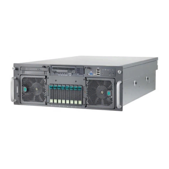
Preface The PRIMERGY RX600 S4 server is an Intel-based server for mid-size and large companies. The server is suitable for use as a file server and also as an application, information or Internet server. It is used as a rack model. -
Page 8: Documentation Overview
Documentation overview Preface Documentation overview More information on your PRIMERGY RX600 S4 can be found in the following documents: – “Quick Start Hardware - PRIMERGY RX600 S4” leaflet (only included as a printed copy) – “Quick Start Software - Quick Installation Guide” leaflet (only included as a printed copy) –... -
Page 9: Features
– Information files on your operating system Features Customer Self Service (CSS) The Fujitsu Siemens Computers Customer Self Service (CSS) concept enables you to identify and replace the affected component yourself in the case of certain error scenarios. In the CSS concept, you can replace the following components yourself in the event of an error: –... - Page 10 Features Preface In the event of errors, ServerView S2 refers you directly to the affected component and its order information in the Illustrated Spares catalog of the server in question. System board The features of the system board are described in the technical manual for the system board D2244 for the hardware and in the “BIOS Setup”...
- Page 11 Preface Features Accessible drives/components A number of mounting locations are available: – An installation slot for a ServerView Local Service Display (standard) – An installation slot for a slimline CD/DVD drive (option) – A 5.25-inch bay for a magnetic tape drive (option) The accessible drives/components integrated in this locations cannot be replaced during operation.
- Page 12 ASR&R (Automatic Server Reconfiguration and Restart) restarts the system in the event of an error and automatically "hides" the defective system compo- nents. The PDA (Prefailure Detection and Analysis) technology from Fujitsu Siemens Computers analyzes and monitors all components that are critical for system reliability.
- Page 13 Preface Features iRMC S2 with integrated service LAN port The features of the iRMC S2 Advanced Video Redirection and Remote Storage are available as an option. The iRMC S2 (integrated Remote Management Controller) is a BMC with integrated service LAN port and expanded functionality that was previously only available with additional plug-in cards.
- Page 14 Server management Server management is implemented using the ServerView software supplied combined with PDA (Prefailure Detection and Analysis) technology from Fujitsu Siemens Computers. PDA reports the threat of a system error or overload at an early stage, allowing preventive measures to be taken.
- Page 15 For further information, please refer to the diagnosis LEDs on the hot-plug components (power supply unit, fans, expansion cards, HDD modules). The Global Flash program supplied with the Fujitsu Siemens Computers utilities supports a fast remote BIOS update via the LAN interface; the BIOS can be updated locally via USB.
- Page 16 ServerView Remote Management ServerView Remote Management is the remote management solution from Fujitsu Siemens Computers for PRIMERGY servers. ServerView Remote Management and the relevant hardware components integrated on the system board allow remote monitoring and maintenance as well as fast restoration of operation in the event of errors.
-
Page 17: Notational Conventions
Preface Notational conventions Notational conventions The following notational conventions are used in this manual: Text in italics indicates commands or menu items. “Quotation marks” indicate names of chapters and terms that are being emphasized. Ê describes activities that must be performed in the order shown. - Page 18 Technical data Preface Compliance with regulations and standards Product safety and IEC 60950-1 / EN 60950-1, UL/CSA 60950-1, ergonomics CNS 14336 / GB 4943 / EN 50371 Electromagnetic compatibility Interference EN 55022 class A; FCC class A; CNS 13438 class A; emissions VCCI class A;...
- Page 19 Preface Technical data Weight Approx. 40 kg (depending on configuration). Ventilation clearance At least 200 mm on the front and rear. Ambient conditions Environment class 3K2 EN 60721 / IEC 721 Part 3-3 Environment class 2K2 EN 60721 / IEC 721 Part 3-2 Temperature: Operation (3K2) 10 °C ..
-
Page 21: Overview Of The Installation Steps
Overview of the installation steps This chapter contains an overview of the steps necessary to install your server. Links guide you to sections where you can find more detailed information on the individual steps: Ê At first, please take notice of the safety instructions in chapter “Important information”... - Page 22 Overview of the installation steps Ê Configure the server and install the desired operating system and applica- tions. Here you can choose from two possibilities: – Remote configuration and installation with ServerStart: The ServerStart disc 1 supplied allows you to conveniently configure the server and install the operating system.
-
Page 23: Important Information
Important information In this chapter you will find essential information regarding safety when working on your server. Safety instructions The following safety instructions are also provided in the manual “Safety notes and other important information”. This device meets the relevant safety regulations for IT equipment. If you have any questions about whether you can install the server in the intended environment, please contact your sales outlet or our customer service team. - Page 24 Safety instructions Important information Before starting up CAUTION! During installation and before operating the device, observe the instructions on environmental conditions for your device (see “Technical data” on page 17). If the server has been moved from a cold environment, condensation may form both inside and on the outside of the machine.
- Page 25 Important information Safety instructions CAUTION! Ensure that the power sockets on the device and the grounded shock- proof sockets are freely accessible. The On/Off button or the main power switch (if present) does not isolate the device from the mains power supply. To disconnect it completely from the mains power supply, unplug all network power plugs from the grounded shockproof sockets.
- Page 26 Safety instructions Important information CAUTION! Proper operation of the system (in accordance with IEC 60950-1/ EN 60950-1) is only ensured if the casing is completely assembled and the rear covers for the installation slots have been fitted (electric shock, cooling, fire protection, interference suppression). Only install system expansions that satisfy the requirements and rules governing safety and electromagnetic compatibility and those relating to telecommunication terminals.
- Page 27 Important information Safety instructions Batteries CAUTION! Incorrect replacement of batteries may lead to a risk of explosion. The batteries may only be replaced with identical batteries or with a type recommended by the manufacturer (see the technical manual for the system board).
- Page 28 Safety instructions Important information Working with CDs/DVDs and CD/DVD drives When working with devices with CD/DVD drives, these instructions must be followed. CAUTION! Only use CDs/DVDs that are in perfect condition in your server's CD/DVD drive, in order to prevent data loss, equipment damage and injury.
- Page 29 Important information Safety instructions Modules with Electrostatic-Sensitive Devices Modules with electrostatic-sensitive devices are identified by the following sticker: Figure 1: ESD label When you handle components fitted with ESDs, you must always observe the following points: Switch off the system and remove the power plugs from the power outlets before installing or removing components with ESDs.
-
Page 30: Ce Conformity
CE conformity Important information Other important information: During cleaning, observe the instructions in section “Cleaning the server” on page Keep this operating manual and the other documentation (such as the technical manual, CD) close to the device. All documentation must be included if the equipment is passed on to a third party. -
Page 31: Fcc Class A Compliance Statement
Consult the dealer or an experienced radio/TV technician for help. Fujitsu Siemens Computers is not responsible for any radio or television inter- ference caused by unauthorized modifications of this equipment or the substi- tution or attachment of connecting cables and equipment other than those specified by Fujitsu Siemens Computers. -
Page 32: Transporting The Server
Transporting the server Important information WARNING: This is a class A product. In a domestic environment this product may cause radio interference in which case the user may be required to take adequate measures. Transporting the server CAUTION! Only transport the server in its original packaging or in packaging that protects it from impacts and jolts. -
Page 33: Notes On Installing In The Rack
Important information Notes on installing in the rack Notes on installing in the rack CAUTION! For safety reasons, at least two people are required to install the rack model because of its weight and size. Never lift the server into the rack using the handles on the front panel. When connecting and disconnecting cables, observe the relevant instructions in the “Important Information”... -
Page 34: Environmental Protection
Important information Environmental protection Environmentally-friendly product design and development This product has been designed in accordance with the Fujitsu Siemens Computers standard for “environmentally friendly product design and devel- opment”. This means that key factors such as durability, selection and labeling of materials, emissions, packaging, ease of dismantling and recycling have been taken into account. - Page 35 Details regarding the return and recycling of devices and consumables within Europe can also be found in the “Returning used devices” manual, via your local Fujitsu Siemens Computers branch or from our recycling center in Paderborn: Fujitsu Siemens Computers Recycling Center D-33106 Paderborn Tel.
-
Page 37: Hardware Installation
Hardware installation CAUTION! Follow the safety instructions in the chapter “Important information” on page Do not expose the server to extreme environmental conditions (see “Ambient conditions” on page 19). Protect the server from dust, humidity and heat. Make sure that the server is acclimatized for the time indicated in this table before putting it into operation. -
Page 38: Unpacking The Server
Unpacking the server Hardware installation Unpacking the server CAUTION! Follow the safety instructions in chapter “Important information” on page The server must always be lifted or carried by at least two people. Do not unpack the server until it is at its installation location. Ê... -
Page 39: Rack Installation/Removal Of Server
The power is supplied via the multiple socket outlets fitted in the rack. The main features of the rack systems from Fujitsu Siemens Computers are as follows: PRIMECENTER Rack –... - Page 40 Rack installation/removal of server Hardware installation DataCenter Rack – Directly laterally bolted telescopic rails or sliding rails (except within the rear left area where a support bracket is used). – Enhanced cable management in the lateral rack area. The mounting of the rails in the different racks is described in the next sections. Installation of the cable management is described in detail in the Technical Manual for the respective rack.
- Page 41 Hardware installation Rack installation/removal of server Figure 2: Mechanical requirements Operating manual RX600 S4...
- Page 42 Rack installation/removal of server Hardware installation – You must ensure that the safety mechanisms on the server, e.g. stoppers or retaining systems, are functioning correctly. – The shape of the rack support uprights must ensure that the rails can be bolted to the front.
-
Page 43: Mounting In The Primecenter Rack
Hardware installation Rack installation/removal of server 4.2.1 Mounting in the PRIMECENTER Rack For mounting the server in the PRIMECENTER Rack the following parts are necessary: – a support bracket with two M5x10 screws including centering disks – a rack mount kit, comprising two telescopic rails (left/right), completely mounted –... - Page 44 Rack installation/removal of server Hardware installation For better orientation the height units are marked on the support uprights. Figure 4: Mounting the telescopic rails in the PRIMECENTER Rack Ê Position the left vario support system with mounted telescopic rail (1) on the support bracket (insert retaining bolts).
-
Page 45: Installation In The Datacenter Rack
Hardware installation Rack installation/removal of server Ê Fit the PRIMECENTER Rack cable management as described in the technical manual for the PRIMECENTER Rack. Ê Insert the server (see section “Inserting the server” on page 46). Ê Route the cables once the server has been inserted, as described in the Technical Manual for the PRIMECENTER Rack. -
Page 46: Inserting The Server
Rack installation/removal of server Hardware installation 4.2.4 Inserting the server CAUTION! At least two people are needed to position the server in the rack. Ê Fully extend the fitted telescopic rails. They must click into place so that they can no longer be moved. Figure 5: Inserting the server Ê... - Page 47 Hardware installation Rack installation/removal of server The following steps can then be carried out by one person only. Figure 6: Unlock telescopic rails and push server into the rack Ê Press the safety catch (1) on the outside of the two rails upwards in the direction of the arrow and push the server into the rack in the direction of the arrow (2).
- Page 48 Rack installation/removal of server Hardware installation Figure 7: Securing the server Ê Place the cage nuts for fastening the front panel in the corresponding holes of the front support uprights and fasten the server using two knurled screws (1). To remove the server, follow this procedure in reverse. When removing the server, make sure that the two system support rods (see figure 5 on page are pulled out parallel right and left.
-
Page 49: Connecting Devices To The Server
Hardware installation Connecting devices to the server Connecting devices to the server The ports for external devices are on the front and rear of the server. The additional ports available on your server depend on the expansion cards installed (e.g. optional SCSI port). Some of the devices that can be connected may require special software, e.g. - Page 50 Connecting devices to the server Hardware installation The standard ports on the rear are marked with symbols, and some are color- coded: Figure 9: Ports on the left side of the rear 1 2 x USB ports 3 Serial port COM1 (turquoise) 2 Monitor port (blue) Operating manual RX600 S4...
- Page 51 Hardware installation Connecting devices to the server There are further ports at the rear right, see figure 10. Figure 10: Ports on the right side of the rear 1 Service LAN port 3 LAN port 1 2 2 x LAN ports 4 LAN port 2 Ê...
-
Page 52: Connecting The Server To The Mains
Connecting the server to the mains Hardware installation Connecting the server to the mains The server has two hot-plug power supply units. This ensures redundant power supply. If one power supply unit is defective, the other then guarantees unimpaired operation. Each hot-plug power supply unit can be replaced during operation (see “Replacing the hot-plug power supply unit”... -
Page 53: Connecting The Monitor
Hardware installation Connecting the monitor Figure 12: Securing the power cord in the cable clamp Ê Secure the power cords in the cable clamps so the insulated connectors cannot be disconnected from the server accidentally. Connecting the monitor Ê Plug the data cable for the monitor into the monitor port on the server. Alter- natively, the monitor port at the front or the rear of the server can be used. -
Page 54: Notes On Connecting/Disconnecting Cables
Notes on connecting/disconnecting cables Hardware installation Notes on connecting/disconnecting cables CAUTION! Always read the documentation supplied with the device you wish to connect. Never connect, or disconnect cables during a thunderstorm. Never pull on a cable when disconnecting it. Always take hold of the cable by the plug. -
Page 55: Starting Up And Operation
Starting up and operation CAUTION! Follow the safety instructions in chapter “Important information” on page Controls and indicators 5.1.1 Front of server Figure 13: Front - detailed view: port and control panel Monitor port ID indicator 3 x USB ports ID button Hard disk activity indicator On/Off button... -
Page 56: Controls
Controls and indicators Starting up and operation Figure 14: Front - overall view 1 ServerView Local Service Display 4 Hard disk drive indicators 2 CD/DVD drive activity indicator 5 Accessible drive (optional) 3 Fan indicator 6 Fan indicator 5.1.1.1 Controls NMI button Do not press! The NMI button may only be used by service personnel. -
Page 57: Indicators On The Control Panel
Starting up and operation Controls and indicators ID button Lights up (blue) on the front and on the rear of the server when the ID button is pressed. The two ID indicators are synchronized. 5.1.1.2 Indicators on the control panel Hard disk activity indicator (green/orange) Lights up or flashes green if one of the SAS hard disk drives controlled by the SAS Controller is being accessed. - Page 58 Controls and indicators Starting up and operation CSS/Global Error indicator (yellow/orange) Generally, the three possible states of this indicator have the following meanings: – Does not light up when the system is OK. – If the event is still acute after a power failure, the indicator is activated after the restart.
-
Page 59: Indicators On The Accessible Drives/Components
Starting up and operation Controls and indicators Power-on indicator (green/orange) Lights up green when the server is switched on and ready. Flashes green when the server is switched on and is in sleep mode (ACPI state S1). Lights up orange when the server is switched off (ACPI state S5). Does not light when the server is switched off. -
Page 60: Indicators On The Hdd Modules
Controls and indicators Starting up and operation 5.1.1.4 Indicators on the HDD modules Figure 15: Indicators on an HDD module HDD BUSY (green) – Lights up: HDD in active phase – Does not light: HDD inactive (drive inactive) HDD FAULT (orange) –... -
Page 61: Indicator On The Fan Modules
Starting up and operation Controls and indicators 5.1.1.5 Indicator on the fan modules Figure 16: Fan status indicator (right fan module) The server has two fan modules each with two hot-plug system fans. The fan status indicator (1) visible at the front relates to both fans in a module. Fan indicator Meaning does not light... -
Page 62: Rear Of Server
Controls and indicators Starting up and operation 5.1.2 Rear of server 5.1.2.1 LAN indicators Figure 17: LAN indicators (rear right) 1 LAN activity indicator (service LAN) Lights up green if a LAN connection exists. Does not light up if no LAN connection exists. Flashes green when a LAN transfer is in progress. -
Page 63: Css Indicator
Starting up and operation Controls and indicators The LAN activity indicators are synchronous with the LAN indicators on the front of the server (see “Indicators on the control panel” on page 57). 5.1.2.2 CSS indicator Figure 18: CSS indicator (rear right) 1 CSS indicator (yellow) Does not light up when the system is OK. -
Page 64: Global Error Indicator
Controls and indicators Starting up and operation 5.1.2.3 Global Error indicator Figure 19: Global Error indicator (rear right) 1 Global Error indicator (orange) Does not light up when the system is OK. No service incident or critical event has occurred. Flashes orange when a critical event has occurred. -
Page 65: Id Indicator And Id Button
Starting up and operation Controls and indicators 5.1.2.4 ID indicator and ID button Figure 20: ID indicator and ID button (rear right) 1 ID indicator (blue) Lights up blue when the system has been selected by pressing the ID button (2). To deactivate, press the button again. The ID indicator can also be activated via ServerView and its status reported to ServerView. -
Page 66: Indicators On The Hot-Plug Power Supply Units
Controls and indicators Starting up and operation 5.1.2.5 Indicators on the hot-plug power supply units Figure 21: Indicators on the power supply units (right power supply unit) 1 Switch-on indicator (green) Lights up when the server is switched on. 2 Fault indicator (orange) Lights up if there is a fault in the power supply unit. -
Page 67: Switching The Server On And Off
Starting up and operation Switching the server on and off Switching the server on and off CAUTION! It nothing appears on the screen but flickering stripes after switching on the server, switch the server off immediately (see chapter “Trouble- shooting and tips” on page 75). - Page 68 Switching the server on and off Starting up and operation Switching the server off The power-on indicator lights up green (item 6 in figure 13 on page 55). Ê Shut down the operating system properly. The server is switched off automatically and goes into standby mode. The power-on indicator lights up orange.
-
Page 69: Configuring The Server
Starting up and operation Configuring the server Configuring the server This section contains information about configuring the server and installing the operating system. Make sure that the energy saving functions are disabled in the BIOS Setup during server operation. 5.3.1 Configuring onboard SAS RAID controller You can configure the RAID either before or during ServerStart. -
Page 70: Configuration With Serverstart
Configuring the server Starting up and operation 5.3.2 Configuration with ServerStart The ServerStart disc 1 supplied allows you to conveniently configure the server and install the operating system. Menu-guided configuration includes server configuration with the SCU and RAID controller configuration with ServerVie- wRAID. -
Page 71: Configuration Without Serverstart
Starting up and operation Cleaning the server 5.3.3 Configuration without ServerStart Configuring onboard SAS RAID controller Configure the controller as described in section “Configuring onboard SAS RAID controller” on page Installing the operating system Ê Insert the CD for the operating system you want to install. Ê... -
Page 73: Property And Data Protection
Property and data protection Mechanical access protection The lockable rack door protects the server against unauthorized access. BIOS Setup security functions The Security menu in BIOS Setup offers various options for protecting your data from unauthorized access. For example, you can assign passwords for users and administrators. -
Page 75: Troubleshooting And Tips
Troubleshooting and tips CAUTION! Follow the safety instructions in the “Safety notes and other important information” manual and in chapter “Important information” on page If a fault occurs, attempt to resolve it using the measures described: – in this chapter, –... -
Page 76: Server Switches Itself Off
Server switches itself off Troubleshooting and tips Server switches itself off Server Management has detected an error Ê Check the error list or the ErrorLog file in the ServerView program, and attempt to eliminate the error. Screen remains blank Monitor is switched off Ê... -
Page 77: Flickering Stripes On Monitor Screen
Troubleshooting and tips Flickering stripes on monitor screen Flickering stripes on monitor screen CAUTION! Switch off the server immediately. Risk of damaging the server. Monitor does not support the set horizontal frequency Ê Find out which horizontal frequency your monitor screen supports. You will find the horizontal frequency (also known as line frequency or horizontal deflection frequency) in the documentation for your monitor. -
Page 78: Incorrect Date And Time
Incorrect date and time Troubleshooting and tips Incorrect date and time Ê Set the date and time in the operating system or in the BIOS Setup under the Main menu, using System Date and System Time respectively. Note that the operating system may affect the system time. For example, the operating system time may deviate from the system time under Linux, and would overwrite the system time in the default setting on shutdown. -
Page 79: Added Drive Reported As Defective
Troubleshooting and tips Added drive reported as defective Added drive reported as defective RAID controller is not configured for this drive The drive was probably installed when the system was switched off. Ê Reconfigure the RAID controller for the drive using the corresponding utility. Information is provided in the documentation for the RAID controller. -
Page 81: Css Components
CSS components This chapter describes how to handle CSS components and how to identify defective CSS components and replace them yourself. Further information on the CSS concept is provided in the “Customer Self Service (CSS)” manual on the ServerBooks DVD. Upgrades, updates and replacement of non-CSS components are described in the “Options Guide”... -
Page 82: Hot-Plug Components
Hot-plug components CSS components Hot-plug components This section describes how to handle the hot-plug components and/or how to modify your server hardware (e.g. adding/replacing hot-plug power supply units or hot-plug HDD modules). The hot-plug procedure increases the availability of system operation and guarantees a high degree of data integrity and failsafe performance. - Page 83 CSS components Hot-plug components Figure 22: Unlocking and removing the power supply unit Ê Remove the cable of the defective power supply unit. Ê Briefly press the green point (1). This releases the locking lever. Ê Rotate the locking lever in the direction of the arrow (2). Ê...
-
Page 84: Replacing Hot-Plug Cpu Fans
Hot-plug components CSS components If everything is functioning correctly, the green LEDs 1 and 3 (see “Indicators on the hot-plug power supply units” on page 66) at the rear of the power supply unit will now light up. 8.1.2 Replacing hot-plug CPU fans The server has two pairs of redundant hot-plug CPU fan (2+2). - Page 85 CSS components Hot-plug components Figure 23: Unlocking fan module left and removing it Ê Briefly press the green point (1). The handle (2) is released. Use the handle to pull out the defective fan module. CAUTION! Never leave the fan module slot empty for more than two minutes during operation.
-
Page 86: Replacing Hot-Plug Main Memory Fans
Hot-plug components CSS components 8.1.3 Replacing hot-plug main memory fans CAUTION! The actions described in this section may only be performed by personnel with the appropriate technical training. Any unauthorized openings and improper repairs could expose the user to risks (electric shock, fire hazards) and could also damage the equipment. - Page 87 CSS components Hot-plug components Ê Open the housing cover (see “Opening/closing the housing” on page 114). Figure 24: Diagnostic LED on main memory fan Ê Use the diagnostic LED (1) to identify the faulty fan. The diagnostic LED lights up/flashes orange. Figure 25: Exchanging the fan Ê...
- Page 88 Hot-plug components CSS components CAUTION! Never set a removed/defective fan down inside the server. Risk of short circuit! Mounting is performed in the reverse order. The new fans are measured with explicit commands in Server Management. Depending on the result, the corresponding LED is set to orange (fan is not in order).
-
Page 89: Hot-Plug Hard Disk Drives
Up to eight hot-plug hard disk drives can be installed in the PRIMERGY RX600 S4 Server. The hard disk drives which can be ordered for the PRIMERGY RX600 S4 are supplied already mounted in an installation frame so that defective hard disk drives can be replaced and new drives can be added during operation. -
Page 90: Handling Hard Disk Drives And Hdd Modules
Hot-plug components CSS components 8.1.4.1 Handling hard disk drives and HDD modules Hard disk drives incorporated in the HDD modules are highly sensitive electro- magnetic devices and must be handled with great care. Incorrect handling can cause partial or total failure of the hard disk drives. These failures can result in data errors and to a loss of data or to total corruption of the hard disk drive. -
Page 91: Removing/Installing The Dummy Module
CSS components Hot-plug components 8.1.4.2 Removing/installing the dummy module Free slots are provided with dummy modules. Remove the dummy module before installing an additional HDD module. Figure 26: Removing the dummy module Ê Press both tabs on the dummy module together until the locking mechanism disengages (1). -
Page 92: Installing/Removing The Hdd Module
Hot-plug components CSS components 8.1.4.3 Installing/removing the HDD module Unlocking the HDD module Figure 27: Unlocking the HDD module Ê Release the locking mechanism by pressing the locking button (1). Ê Push the handle of the HDD module fully in the direction of the arrow (2). The HDD module is now unlocked. - Page 93 CSS components Hot-plug components Installing the HDD module Ê Unlock the HDD module as described in section “Unlocking the HDD module” on page Figure 28: Pushing the HDD module into the slot Ê Carefully push the HDD module into the empty slot until it stops. Operating manual RX600 S4...
- Page 94 Hot-plug components CSS components Figure 29: Lock the HDD module Ê Push the handle completely until the locking mechanism engages. Operating manual RX600 S4...
- Page 95 CSS components Hot-plug components Removing the HDD module CAUTION! Only remove an HDD module during operation if the drive is not currently being accessed. Observe the control LEDs for the corre- sponding HDD modules (see “Indicators on the HDD modules” on page 60).
- Page 96 Hot-plug components CSS components Ê Install the new HDD module, as described in “Unlocking the HDD module” on page 92 “Installing the HDD module” on page CAUTION! If you have removed a HDD module and do not install a new one in its place, put the dummy module back in its place for cooling, to comply with EMC regulations (regulations regarding electromagnetic compatibility), and for protection against fire.
-
Page 97: Hot-Plug Expansion Cards
CSS components Hot-plug components 8.1.5 Hot-plug expansion cards CAUTION! The actions described in this section may only be performed by personnel with the appropriate technical training. Any unauthorized openings and improper repairs could expose the user to risks (electric shock, fire hazards) and could also damage the equipment. Please observe the safety information in chapter “Important infor- mation”... -
Page 98: Removing A Hot-Plug Expansion Card
Hot-plug components CSS components Figure 30: Slots with and without hot-plug functionality Slots 1 - 4 (green locks) are hot-plug slots. Slots 5 - 7 (blue locks) are slots without hot-plug functionality. The server must be switched off before expansion cards are replaced or inserted in these slots. - Page 99 CSS components Hot-plug components Figure 31: Deactivating, unlocking and removing the board Ê Deactivate the expansion card using either the relevant PCI hot-plug software or by pressing the optical waveguide (1). Ê Wait until the optical waveguide (1) no longer lights up. The slot is now zero potential.
- Page 100 Hot-plug components CSS components Removing expansion card from the removal tool CAUTION! When removing the expansion card from the removal tool, pay particular attention to the engaging hooks that fasten the board to the removal tool (see figure 32 on page 100).
- Page 101 CSS components Hot-plug components Removing engaging hooks Figure 33: Removing engaging hooks from the removal tool Ê Push the green engaging hooks down in the direction of the arrow (1) until they disengage from the removal tool. Ê Remove the engaging hooks (2) and keep them in a safe place. Ê...
-
Page 102: Removing A Dummy Module
Hot-plug components CSS components 8.1.5.2 Removing a dummy module If a slot does not contain an expansion card, it is occupied by a dummy module. This is a retaining plate with an attached removal tool. Before inserting an additional hot-plug expansion card, you will first have to remove the dummy module from its slot. -
Page 103: Installing A Hot-Plug Expansion Card
CSS components Hot-plug components Keep the retaining plate for future use. Ê Push the engaging hooks down until they disengage from the removal tool (see figure 33 on page 101), and keep them in a safe place. 8.1.5.3 Installing a hot-plug expansion card Inserting an expansion card in the removal tool Figure 35: Inserting the new expansion card in the removal tool Ê... - Page 104 Hot-plug components CSS components Ê Insert the green engaging hooks in the rods and push them down until they engage in the upper edge of the expansion card. CAUTION! Make sure that the ports on the expansion card are not blocked by the engaging hooks.
-
Page 105: Replacement Of Non-Hot-Plug Components
CSS components Replacement of non-hot-plug components Replacement of non-hot-plug components 8.2.1 Replacing a memory module CAUTION! The actions described in this section may only be performed by personnel with the appropriate technical training. Any unauthorized openings and improper repairs could expose the user to risks (electric shock, fire hazards) and could also damage the equipment. - Page 106 Replacement of non-hot-plug components CSS components Ê Open the server (see “Opening/closing the housing” on page 114). Figure 36: Example: Diagnostic LEDs on memory board B Ê Use the diagnostic LEDs (1-8) to identify the faulty memory module. The diagnostic LED lights up/flashes orange and indicates the slot on the memory board (1-8) that is occupied by the faulty memory module.
-
Page 107: Removing The Memory Board In Question
CSS components Replacement of non-hot-plug components 8.2.1.1 Removing the memory board in question Figure 37: Example: Removing memory board A Ê Unlock the memory board in question. Ê Lift the memory board up and out. Operating manual RX600 S4... - Page 108 Replacement of non-hot-plug components CSS components Figure 38: Removing the memory board cover Ê Remove the cover on the memory board by pressing the marked tabs. First press tabs 1 and 2, then tab 3. Operating manual RX600 S4...
-
Page 109: Removing A Defective Memory Module
CSS components Replacement of non-hot-plug components 8.2.1.2 Removing a defective memory module Figure 39: Identify the slot on the memory board Ê Identify the slot with the defective memory module (see page 106). The slots on the memory board are numbered 1 through 8 ("DIMM 1" to "DIMM 8"). - Page 110 Replacement of non-hot-plug components CSS components Figure 40: Removing a memory module Ê Press the holders on either side of the mounting location concerned outward (1). Ê Pull the defective memory module out of the slot (2). Operating manual RX600 S4...
-
Page 111: Installing A New Memory Module
CSS components Replacement of non-hot-plug components 8.2.1.3 Installing a new memory module CAUTION! The faulty memory module must only be replaced by an identical memory module. Figure 41: Inserting a memory module Ê Carefully press the memory module into the slot (1) until the fastening tabs on both sides of it engage (2). -
Page 112: Reinstalling The Memory Board In Question
Replacement of non-hot-plug components CSS components 8.2.1.4 Reinstalling the memory board in question Figure 42: Placing the cover on the memory board Ê Place the cover back on the memory board by pressing the marked tabs. First press tab 3, then tabs 1 and 2. Operating manual RX600 S4... - Page 113 CSS components Replacement of non-hot-plug components Figure 43: Example: Installing memory board A Ê Slide the memory board down in the lateral guide channels until it engages in the slot. Ê Make sure that the locks on the sides engage. Operating manual RX600 S4...
-
Page 114: Opening/Closing The Housing
Opening/closing the housing CSS components Opening/closing the housing CAUTION! The actions described in this section may only be performed by personnel with the appropriate technical training. Any unauthorized openings and improper repairs could expose the user to risks (electric shock, fire hazards) and could also damage the equipment. CAUTION! The housing cover must be replaced as soon as possible for purposes of cooling, to comply with EMC regulations (regulations regarding electro-... -
Page 115: Abbreviations
Abbreviations Alternating Current ACPI Advanced Configuration and Power Interface ANSI American National Standards Institute ASR&R Automatic Server Reconfiguration and Restart Battery Backup Unit BIOS Basic Input-Output System Baseboard Management Controller British Thermal Unit Cache Coherency Compact Disk CD-ROM Compact Disk-Read Only Memory Cylinder Head Sector CMOS Complementary Metal Oxide Semiconductor... - Page 116 Abbreviations Communications Central Processing Unit Customer Replaceable Unit Customer Self Service Direct Current DIMM Dual Inline Memory Module Dual Inline Package Direct Memory Access Desktop Management Interface Digital Versatile Disk Error Checking and Correcting Extended Capabilities Port EEPROM Electrically Erasable Programmable Read-Only Memory Extensible Firmware Interface Operating manual RX600 S4...
- Page 117 Abbreviations Electronic Industries Alliance Emergency Management Port Enhanced Parallel Port Elektromagnetische Verträglichkeit (electromagnetic compatibility) EPROM Erasable Programmable Read-Only Memory ElectroStatic Discharge File Allocation Table Front Panel Controller Field Replaceable Unit Front Side Bus Graphical User Interface Hard Disk Drive Hot-Swap Controller Height Unit Operating manual RX600 S4...
- Page 118 Abbreviations I²C Inter-Integrated Circuit Input/Output Intelligent Chassis Management Identification Integrated Drive Electronics International Electrotechnical Commission Integrated Mirroring Enhanced IPMI Intelligent Platform Management Interface Interrupt Request Line Local Area Network Logical Block Address Liquid Crystal Display Local Diagnostic LED Light Emitting Diode Operating manual RX600 S4...
- Page 119 Abbreviations Low Profile Logical Unit Number Low-Voltage Differential SCSI LichtWellenLeiter (fiber optic cable) Manual Retention Latch Multi Mode Faser Non Maskable Interrupt NTFS New Technology File System NVRAM Non Volatile Random Access Memory Operating System Peripheral Component Interconnect Prefailure Detection and Analysis Portable Data Format POST Power ON Self Test...
- Page 120 Abbreviations PS/2 Personal System/2 RAID Redundant Arrays of Independent Disks Random Access Memory RoHS Restriction of the Use of Certain Hazardous Substances (Waste from Electric and Electronic Equipment) Read-Only Memory RoMB RAID on Mother Board Remote Service Board Real Time Clock RTDS Remote Test- und Diagnose-System SAF-TE...
- Page 121 Abbreviations SCSI Small Computer System Interface System Configuration Utility Sensor Data Record SDRAM Synchronous Dynamic Random Access Memory System Event Log S.M.A.R.T Self-Monitoring, Analysis, and Reporting Technology System Management Interrupt Service Replaceable Unit System Setup Utility SVGA Super Video Graphics Adapter Universal Serial Bus Video Graphics Adapter WEEE...
-
Page 123: Index
Index connecting cables 3rd party rack connection panel 49, installing server consumables requirements control panel 56, controls ID button 55, accessible drives on/off button DVD 11, 56, reset button 55, magnetic tape cooling acclimatization time 37, correcting faults Advanced Video Redirection CPU fan ambient conditions CSS indicator... - Page 124 Index EMC directive hard disk drive EMC regulations 91, 96, handling environment class HDD module environmental protection indicators error installation frame drifting display on monitor HDD module drive “dead” acclimatization time 37, drive defective dummy module incorrect date handling incorrect time indicators no display on monitor installation frame...
- Page 125 Index DataCenter Rack 40, operation installation in rack 39, configuring the server ports control panel 56, PRIMECENTER Rack 39, indicators rack requirements server switch on/off telescopic rails 43, installation overview packaging 34, installing in the rack, notes PCI slots integrated Remote Management dummy module Controller expansion cards, replacing...
- Page 126 Index rating plate support recycling devices switches itself off (error) regulations and standards switching on/off Remote Storage technical data replace system fan transport reset button 55, troubleshooting return of devices unpacking voltage range 11, server management safety precautions ServerStart 15, safety standards ServerView SAS controller 10,...
Need help?
Do you have a question about the PRIMERGY RX600 S4 and is the answer not in the manual?
Questions and answers