Table of Contents
Advertisement
Quick Links
SmartNode™ 4660 & 4670 Series
Multiport BRI/FXS/FXO VoIP
Gateway-Router, IAD
User Manual
This is a Class B device and is intended for use in a light industrial (commercial) or residential environment. It is not intended
for use in a heavy industrial environment.
If a copper module is used, it may void the CE Certification. This product is intended for Fiber SFP modules only.
REGULATORY MODEL NUMBER: 13243D4-001
Sales Office:
+1 (301) 975-1000
Technical Support:
+1 (301) 975-1007
E-mail:
support@patton.com
www.patton.com
Part Number: 07MSN4660-4670-UM, Rev. C
Revised: June 4, 2014
Advertisement
Table of Contents

Related Manuals for Patton SmartNode 4660 Series


Summary of Contents for Patton SmartNode 4660 Series
-
Page 1: User Manual
If a copper module is used, it may void the CE Certification. This product is intended for Fiber SFP modules only. REGULATORY MODEL NUMBER: 13243D4-001 Sales Office: +1 (301) 975-1000 Technical Support: +1 (301) 975-1007 E-mail: support@patton.com www.patton.com Part Number: 07MSN4660-4670-UM, Rev. C Revised: June 4, 2014... - Page 2 E-mail: support@patton.com Trademark Statement The term SmartNode is a trademark of Patton Electronics Company. All other trademarks presented in this document are the property of their respective owners. Copyright © 2013, Patton Electronics Company. All rights reserved. The information in this document is subject to change without notice. Patton Electronics assumes no liability for errors that may appear in this document.
-
Page 3: Table Of Contents
1 General Information ............................. 15 SmartNode 4660 and 4670 Series Overview ......................16 Key Features ..............................17 SmartNode 4660 Series Model Codes......................18 SmartNode 4670 Series Model Codes ......................18 CodesSmartNode 4660 and 4670 Series Rear Panels ....................19 SmartNode 4660 Rear Panel ...........................19 SmartNode 4670 Rear Panel........................... - Page 4 5 Contacting Patton for Assistance........................42 Introduction .................................43 Contact Information ............................43 Patton support headquarters in the USA ......................43 Alternate Patton support for Europe, Middle East, and Africa (EMEA) ............43 Warranty Service and Returned Merchandise Authorizations (RMAs) ..............43 Warranty coverage ............................43 Out-of-warranty service ..........................44 Returns for credit ............................44...
- Page 5 Operating humidity ............................50 System ..................................50 Dimensions ................................50 Weight and Power Dissipation ..........................51 C Cabling ................................. 52 Introduction .................................53 Ethernet ................................53 ISDN BRI ................................54 D Port Pin-outs ..............................55 Console ................................56 Ethernet ................................56 ISDN BRI NT (Net) ............................57 ISDN BRI TE (User) ............................57 FXS ..................................57 FXO ..................................58 G.SHDSL ................................58...
- Page 6 List of Figures 1 SmartNode 4660 (left) and SmartNode 4670 (right) ................16 2 SmartNode 4660 rear panel (Model SN4661/4BIS4JS12V/EUI shown) ..........19 3 SmartNode 4670 rear panel (Model SN4671/4BIS4JS8V2GS/EUI shown) ........21 4 SN4660 application ..........................26 5 SN4670 application ..........................26 6 Connecting the FXS/FXO interface .....................
- Page 7 List of Tables 1 General conventions .............................14 2 SmartNode 4660 Ports and Voice Channels ......................18 3 SmartNode 4670 Ports and Voice Channels ......................18 4 SN4660 rear panel ports ............................19 5 SmartNode SN4660 LED Definitions ........................20 6 SN4670 rear panel ports ............................21 7 SN4670 LED Definitions .............................22 8 SmartNode 4660 LED definitions ........................24 9 SmartNode 4670 LED definitions ........................24...
-
Page 8: Audience
33 provides quick-start procedures for configuring the SmartNode 4660 and 4670 • Chapter 5 on page 40 contains information on contacting Patton technical support for assistance • Appendix A on page 43 contains compliance information for the SmartNode 4660 and 4670 •... -
Page 9: Precautions
SmartNode 4660 & 4670 User Manual About This Guide Precautions Notes, cautions, and warnings, which have the following meanings, are used throughout this guide to help you become aware of potential problems. Warnings are intended to prevent safety hazards that could result in per- sonal injury. -
Page 10: Safety When Working With Electricity
SmartNode 4660 & 4670 User Manual About This Guide Safety When Working with Electricity • Do not open the device when the power cord is connected. For systems without a power switch and without an external power adapter, line voltages are present within the device when the power cord is connected. -
Page 11: General Observations
SmartNode 4660 & 4670 User Manual About This Guide This device contains no user serviceable parts. This device can only be repaired by qualified service personnel. Cet appareil contient des pièces n'est réparable par l'utilisateur. Ce dispositif ne peut être réparé par du personnel qualifié. In accordance with the requirements of council directive 2002/ 96/EC on Waste of Electrical and Electronic Equipment (WEEE), ensure that at end-of-life you separate this product from other... -
Page 12: Typographical Conventions Used In This Document
SmartNode 4660 & 4670 User Manual About This Guide Typographical Conventions Used in this Document This section describes the typographical conventions and terms used in this guide. General Conventions The procedures described in this manual use the following text conventions: Table 1. -
Page 13: General Information
Chapter 1 General Information Chapter contents SmartNode 4660 and 4670 Series Overview......................14 Key Features ..............................15 SmartNode 4660 Series Model Codes ......................16 SmartNode 4670 Series Model Codes ......................16 CodesSmartNode 4660 and 4670 Series Rear Panels.....................17 SmartNode 4660 Rear Panel ...........................17 SmartNode 4670 Rear Panel ...........................19... -
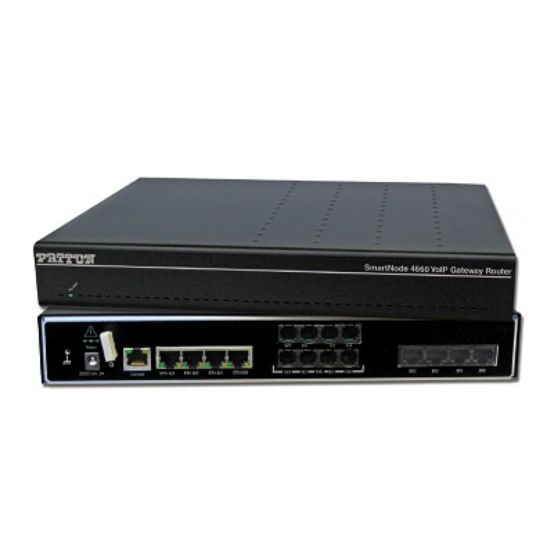
Page 14: Smartnode 4660 And 4670 Series Overview
The SmartNode survivability suite combines PSTN fallback, SIP Registrar and IP-link redundancy to ensure business continuity if the IP network fails. Patton’s DownStreamQoS delivers the advantage of clear, uninter- rupted voice-and-data communication. Furthermore, SmartNode’s unique high-precision clock delivers first- line IP telephony service in demanding ISDN and DECT environments with reliable FAX and modem perfor- mance. -
Page 15: Smartnode 4660 And 4670 Series Overview
SmartNode 4660 & 4670 User Manual 1 • General Information Key Features The SmartNode 4660 and 4670 Series perform the following major functions: • Up to 24 channels for Voice-over-IP or Fax-over-IP (Voice Channels or VC) • All SN4660 and SN4670 models have four 10/100BaseT Ethernet LAN/WAN ports for connection to any existing network device •... -
Page 16: Smartnode 4660 Series Model Codes
SmartNode 4660 & 4670 User Manual 1 • General Information SmartNode 4660 Series Model Codes Table 2. SmartNode 4660 Ports and Voice Channels High Voice Model Ethernet Precision Channels Clock SN4660/8BIS16V/EUI – – – SN4660/4BIS4V/EUI – – – SN4660/4BIS8V/EUI –... -
Page 17: Codessmartnode 4660 And 4670 Series Rear Panels
SmartNode 4660 & 4670 User Manual 1 • General Information CodesSmartNode 4660 and 4670 Series Rear Panels SmartNode 4660 Rear Panel The SmartNode 4660 rear panel ports are described in Table Figure 2. SmartNode 4660 rear panel (Model SN4661/4BIS4JS12V/EUI shown) Table 4. -
Page 18: Codessmartnode 4660 And 4670 Series Rear Panels
SmartNode 4660 & 4670 User Manual 1 • General Information Table 4. SN4660 rear panel ports (Continued) Port Description Reset The reset button (see Figure 2) has three functions: • Restart the unit with the current startup configuration—Press (for less than 1 second) and release the Reset button to restart the unit with the current star- tup configuration. -
Page 19: Smartnode 4670 Rear Panel
SmartNode 4660 & 4670 User Manual 1 • General Information SmartNode 4670 Rear Panel The SmartNode 4670 rear panel ports are described in Table Figure 3. SmartNode 4670 rear panel (Model SN4671/4BIS4JS8V2GS/EUI shown) Table 6. SN4670 rear panel ports Port Description Switched Auto-MDX Fast-Ethernet port, RJ-45 (see Figure... -
Page 20: Smartnode 4670 Rear Panel
• IEEE 802.3 G.998.2 compliant. • SFP tray supporting various Fiber to ethernet converter modules. See http://www.patton.com/products/sfpmodules.asp for tested modules. Used for service and maintenance, the Console port (see Figure 2), an RS-232 RJ- Console 45 connector, connects the SmartNode to a serial terminal such as a PC or ASCII terminal (also called a dumb terminal). - Page 21 SmartNode 4660 & 4670 User Manual 1 • General Information Table 7. SN4670 LED Definitions Definitions ETH 0/0 -0/3 On when the Ethernet connection on the corresponding port has a link indi- cation. Orange LED BRI 0/0 - 0/7 On when Layer1 and Layer2 are active. Act LED BRI 0/0 - 0/7 Off indicates no active calls.
-
Page 22: Smartnode 4660 And 4670 Series Front Panels
SmartNode 4660 & 4670 User Manual 1 • General Information SmartNode 4660 and 4670 Series Front Panels SmartNode 4660 Front panel The LED definitions are listed in Table Table 8. SmartNode 4660 LED definitions Description Power When lit, indicates power is applied and the unit is in normal operation. Off indicates no power applied. -
Page 23: Applications Overview
Chapter 2 Applications Overview Chapter contents Typical Application ..............................24... -
Page 24: Typical Application
SmartNode 4660 & 4670 User Manual 2 • Applications Overview Typical Application IP-enable legacy PBX systems while connecting fax separately with both BRI and FXS/FXO interfaces on one box. Combining a VoIP gateway with an IP router, the SmartNode 4660/4670 adds QoS and VPN security, making it the ideal solution for secure prioritized communications. -
Page 25: Smartnode Installation
SmartNode Installation Chapter 3 Chapter contents Planning the Installation ............................25 Site Log ................................25 Network Information ............................25 Network Diagram ............................25 IP Related Information ...........................26 Software Tools ..............................26 AC Power Mains .............................26 Location and Mounting Requirements ......................26 Installing the SmartNode ............................27 Placing the SmartNode ...........................27 Ground Connection ............................27... -
Page 26: Planning The Installation
28 to install the device. Site Log Patton recommends that you maintain a site log to record all actions relevant to the system, if you do not already keep such a log. Site log entries should include information such as listed in Table Table 10. -
Page 27: Ip Related Information
If you suspect that your AC power is not reliable, for example if room lights flicker often or there is machinery with large motors nearby, have a qualified professional test the power. Patton recommends that you include an uninterruptible power supply (UPS) in the installation to ensure that VoIP service is not impaired if the “Connecting the SmartNode to the power supply”... -
Page 28: Installing The Smartnode
SmartNode 4660 & 4670 User Manual 3 • SmartNode Installation Installing the SmartNode SmartNode hardware installation consists of the following: • “Placing the SmartNode”) Placing the device at the desired installation location (see section • Connecting the interface and power cables (see section “Installing cables”) “Initial Configuration”... -
Page 29: Installing An Interface Cable On The Smartnode's Fxs And Fxo Interface Ports
SmartNode 4660 & 4670 User Manual 3 • SmartNode Installation 4. For SN4671 models, connect the DSL cable (see section “Connecting the SmartNode’s DSL, EFM or Fiber port (SN4670 series only)” on page 30) 5. Connect the power supply (see section “Verify that the green Power LED is lit (see Figure 7).”... -
Page 30: Installation Cable Requirements For The Dsl Wan Cable (Sn4670 Only)
SmartNode 4660 & 4670 User Manual 3 • SmartNode Installation Installation cable requirements for the DSL WAN cable (SN4670 only) The SmartNode Model comes with an option for a G.SHDSL, ADSL, ADD EFM or Fiber interface. Use a straight-through RJ-45 cable to connect the G.SHDSL port. Connecting the SmartNode to the IP network The SmartNode comes with four 10/100 Base-Tx Ethernet ports for connection to an IP network. -
Page 31: Using The Ferrite Clamp
Figure 7. Power connector location on rear panel 3. Verify that the AC power cord included with your SmartNode is compatible with local standards. If it is “Contacting Patton for Assistance” not, refer to Chapter 5, on page 40 to find out how to replace it with a compatible power cord. -
Page 32: External S-Bus Power Supply
SmartNode 4660 & 4670 User Manual 3 • SmartNode Installation • Option 2: Loop a wire tie around the power wire coming out of the end of the ferrite clamp. Repeat the process with the other wire tie on the other end of the clamp. Do not trim the end off of the wire ties. Option 1 Option 2 Two untrimmed... -
Page 33: Initial Configuration
Initial Configuration Chapter 4 Chapter contents Introduction .................................33 Start the SmartNode Discovery Tool ........................33 Access the Web Browser (GUI) Interface ......................34 Configuring your SmartNode ..........................36 Accessing the Internet .............................36 Configuring the default gateway ........................38... -
Page 34: Introduction
The SmartNode discovery tool provides a quick and easy way to access the management interfaces residing within your SmartNode. The tool identifies any Patton VoIP devices installed on your network and displays the model number, IP address and MAC address of each unit.To use the discovery tool, do the following: 1. -
Page 35: Access The Web Browser (Gui) Interface
SmartNode 4660 & 4670 User Manual 4 • Initial Configuration Access the Web Browser (GUI) Interface The SmartNode provides a web-browser-based graphical user interface (GUI) that makes it easy to configure, monitor and manage your SmartNode. To access the web-browser interface, do the following: 1. -
Page 36: Main Gui Elements
SmartNode 4660 & 4670 User Manual 4 • Initial Configuration The SmartNode home page displays three action buttons that allow you to store the current configuration state, reload the device, and restore to factory defaults. The home page also displays certain basic system infor- mation. -
Page 37: Configuring Your Smartnode
SmartNode. The information in this section is intended to introduce the configuration tools and get you started. For more detailed information about configuring your SmartNode, please refer to the SmartWare Configuration Guide available online at www.patton.com/smartnode. The SmartNode immediately applies your changes whenever you modify the configuration. -
Page 38: Ethernet Configuration
SmartNode 4660 & 4670 User Manual 4 • Initial Configuration Figure 14. Ethernet Configuration page The SmartNode supports two configuration options for the Ethernet connection (see Figure 14), as described in the following paragraphs: • DHCP (client—factory default). The SmartNode’s WAN port has a DHCP client enabled that uses an established Internet connection to get the Internet connectivity parameters (IP address, default gateway) automatically from a DHCP server. -
Page 39: Configuring The Default Gateway
SmartNode 4660 & 4670 User Manual 4 • Initial Configuration Configuring the default gateway To configure the default gateway on the SmartNode: 1. In the configuration menu pane, click IP/DNS. Click on the Routes tab. The Configuration screen for 15). Static Routes displays (Figure Figure 15. -
Page 40: Contacting Patton For Assistance
Chapter 5 Chapter contents Introduction .................................40 Contact Information ............................40 Patton support headquarters in the USA ......................40 Alternate Patton support for Europe, Middle East, and Africa (EMEA) ............40 Warranty Service and Returned Merchandise Authorizations (RMAs) ..............40 Warranty coverage ............................40 Out-of-warranty service ..........................41 Returns for credit ............................41... -
Page 41: Introduction
RAS warranty and obtaining a return merchandise authorization (RMA). Contact Information Patton Electronics offers a wide array of free technical services. If you have questions about any of our other products we recommend you begin your search for answers by using our technical knowledge base. Here, we have gathered together many of the more commonly asked questions and compiled them into a searchable database to help you quickly solve your problems. -
Page 42: Out-Of-Warranty Service
RMA#: xxxx 7622 Rickenbacker Dr. Gaithersburg, MD 20879-4773 USA Patton will ship the equipment back to you in the same manner you ship it to us. Patton will pay the return shipping costs. Warranty Service and Returned Merchandise Authorizations (RMAs) -
Page 43: A Compliance Information
Appendix A Compliance Information Chapter contents Compliance ................................43 EMC Compliance ............................43 Low Voltage Directive (Safety) Compliance ....................43 Radio and TV Interference ...........................43 CE Declaration of Conformity ..........................43 Authorized European Representative ........................43... -
Page 44: Compliance
AC outlet (such that the computing equipment and receiver are on different branches). CE Declaration of Conformity Patton Electronics, Inc declares that this device is in compliance with the essential requirements and other rele- vant provisions of Directive 1999/5/EC and Directive 2011/65/EC relating to RoHS compliance. The Decla- ration of Conformity may be obtained from Patton Electronics, Inc at www.patton.com/certifications. - Page 45 Appendix B Specifications Chapter contents ..................................45 Voice Connectivity ...............................45 Data Connectivity ..............................45 Voice Processing (Signaling Dependent) .......................45 Fax and Modem Support ............................45 Voice Signaling ..............................46 Voice Routing—Session Router ...........................46 IP Services ................................46 Management ................................47 Broadband Access (if applicable) ...........................47 Operating Environment ............................47 Operating temperature ............................47...
-
Page 46: B Specifications
SmartNode 4660 & 4670 User Manual B • Specifications Up to three 8/12 channel DSPs Voice Connectivity 2/4/8 ISDN BRI S0 ports, RJ-45. NT/TE configurable per port Point-to-point, point-to-multipoint configurable BRI port provides ISDN line power to connected terminals Data Connectivity Four 10/100Base-TX Ethernet LAN/WAN ports Full duplex, autosensing, auto-MDX Voice Processing (Signaling Dependent) -
Page 47: Voice Signaling
SmartNode 4660 & 4670 User Manual B • Specifications Voice Signaling SIPv2 H.323v4 SIP call transfer, redirect Overlap or en-bloc dialing DTMF in-band, out-of-band Configurable progress tones Voice Routing—Session Router Local switching Interface huntgroups Call-Distribution groups Call Routing Criteria: • Interface •... -
Page 48: Management
EFM: ITU-T G.991.2, Annex A, B, D, F; Up to 22.8 Mbps Fiber: 100 bT and GigE support, 100Mbps and 1000Mbps fiber SFP. See list of tested modules at http:// www.patton.com/products/sfpmodules.asp PPPoE, PPPoA, IPoA 8 PVCs, each UBR, CBR or VBR-rt selectable I.610 OAM F4/F5 support... -
Page 49: Weight And Power Dissipation
SmartNode 4660 & 4670 User Manual B • Specifications Weight and Power Dissipation Table 11. SmartNode weight and maximum power specifications SmartNode model Weight Maximum power dissipation SN4660/SN4661/SN4670/SN4671 <30 oz./1850 g Weight and Power Dissipation... - Page 50 Appendix C Cabling Chapter contents Introduction .................................50 Ethernet ................................50 ISDN BRI ................................51...
-
Page 51: C Cabling
SmartNode 4660 & 4670 User Manual C • Cabling Introduction This section provides information on the cables used to connect the SmartNode and the interface cards to the existing network infrastructure and to third party products. Ethernet Ethernet devices (10Base-T/100Base-Tx) are connected to the SmartNode over a cable with RJ-45 plugs. All Ethernet ports on the SmartNode are Auto-MDX and use any straight or crossover cable to connect to hubs, switches, PCs or other devices. -
Page 52: Isdn Bri
SmartNode 4660 & 4670 User Manual C • Cabling ISDN BRI The ISDN port connects to ISDN terminals (phones, PBXs) or an ISDN S-BUS using cables terminated with RJ-45 connectors. Use straight-though cables to connect to the TE port of your phone, PBX, or residential S-BUS. - Page 53 Appendix D Port Pin-outs Chapter contents Console ................................53 Ethernet ................................53 ISDN BRI NT (Net) ............................54 ISDN BRI TE (User) ............................54 ..................................54 ..................................55 G.SHDSL ................................55 ADSL ...................................55 ..................................55 Fiber ..................................56...
-
Page 54: D Port Pin-Outs
SmartNode 4660 & 4670 User Manual D • Port Pin-outs Console Configuration settings: 9600 bps, 8 bits, no parity, 1 stop bit, no flow control 8–RTS (N/C) 7–CTS (N/C) 6–TD 5–RD 4–SG 3–DTR 2–CD (N/C) 1–DSR 1 2 3 4 5 6 7 8 Pins 1 &... -
Page 55: Isdn Bri Nt (Net)
SmartNode 4660 & 4670 User Manual D • Port Pin-outs ISDN BRI NT (Net) Table 13). The BRI phone port uses an 8-pin RJ-45 connector (the pinout is shown in Table 13. ISDN BRI NT Port: RJ-45 socket Signal Note Pins not listed are not used. -
Page 56: Fxo
SmartNode 4660 & 4670 User Manual D • Port Pin-outs The FXO ports use an RJ-11 connector with 6 positions. The middle two positions, 3 and 4, are used accord- ing to Table Table 16. FXO Port: RJ-11 socket Signal Ring (-) Tip (+) Pins not listed are not used. -
Page 57: Fiber
SmartNode 4660 & 4670 User Manual D • Port Pin-outs Table 19. EFM Port Signal Pair Ring Ring Fiber For tested and approved modules, please refer to the list of SFP’s Patton has tested at http://www.patton.com/ products/sfpmodules.asp. Fiber... -
Page 58: E Smartnode Factory Configuration
Appendix E SmartNode Factory Configuration Chapter contents Introduction .................................58... -
Page 59: Introduction
PROVISIONING now + 1 minute "provisioning execute PF_PROVISIONING_CONFIG" sntp-client sntp-client server primary pool.ntp.org profile provisioning PF_PROVISIONING_CONFIG destination configuration activation reload immediate location 1 http://redirect.patton.com/ $(system.mac);mac=$(system.mac);serial=$(system.serial);hwMajor=$(system.hw.major);hwMi nor=$(system.hw.minor);swMajor=$(system.sw.major);swMinor=$(system.sw.minor);swDate=$(s ystem.sw.date);productName=$(system.product.name);cliMajor=$(cli.major);cliMinor=$(cli. minor);osName=$(cli.major>=4|Trinity|SmartWare);subDirTrinity=$(cli.major>=4|/Trin- ity);subDirSmartWare=$(cli.major<4|/SmartWare);dhcp66=$(dhcp.66);dhcp67=$(dhcp.67) location 2 $(dhcp.66) location 3 $(dhcp.66)/$(system.mac).cfg location 4 http://$(dhcp.66)/$(dhcp.67) location 5 http://$(dhcp.66)/$(system.mac).cfg... -
Page 60: F End User License Agreement
Appendix F End User License Agreement Chapter contents End User License Agreement ..........................60 1. Definitions ..............................60 2. Title ................................60 3. Term ................................60 4. Grant of License ............................60 5. Warranty ..............................60 6. Termination ..............................61 7. Other licenses .............................61 8. SmartWare licenses .............................61... -
Page 61: End User License Agreement
Program(s), even if Patton Electronics Company has been advised of the possibility of such damages. Because some states do not allow the exclusion or limitation of liability for consequential or incidental damages, the above limitation may not apply to you. -
Page 62: Termination
The End User may terminate this agreement by returning the Designated Equipment and destroying all copies of the licensed Program(s). Patton Electronics Company may terminate this Agreement should End User violate any of the provisions of section “4. Grant of License”...
Need help?
Do you have a question about the SmartNode 4660 Series and is the answer not in the manual?
Questions and answers