Table of Contents
Advertisement
Quick Links
For Quick
Start Installation
see page 27
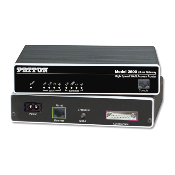
Models 2603, 2621, and 2635
IPLink Series High Speed Routers
User Guide
Sales Office:
+1 (301) 975-1000
Technical Support:
+1 (301) 975-1007
E-mail:
support@patton.com
WWW:
www.patton.com
Document Number: 033261U Rev. A
Part Number: 07M2603
Revised: July 14, 2003
Advertisement
Table of Contents

Related Manuals for Patton IPLink 2603 Series


Summary of Contents for Patton IPLink 2603 Series
-
Page 1: User Guide
27 Models 2603, 2621, and 2635 IPLink Series High Speed Routers User Guide Sales Office: +1 (301) 975-1000 Technical Support: +1 (301) 975-1007 E-mail: support@patton.com WWW: www.patton.com Document Number: 033261U Rev. A Part Number: 07M2603 Revised: July 14, 2003... -
Page 2: Warranty Information
Copyright © 2003, Patton Electronics Company. All rights reserved. The information in this document is subject to change without notice. Patton Elec- tronics assumes no liability for errors that may appear in this document. Warranty Information The software described in this document is furnished under a license and may be used or copied only in accordance with the terms of such license. -
Page 3: Table Of Contents
Contents Contents ................................. 3 Compliance Information ..........................9 Radio and TV Interference ..........................9 CE Notice .................................9 FCC Part 68 (ACTA) Statement (Model 2603 only) ..................9 Industry Canada Notice ............................9 Service ................................10 About this guide ............................11 Audience................................11 Structure................................11 Precautions ................................ - Page 4 Contents Models 2603, 2621, & 2635 High Speed Routers User Guide What you will need ............................28 Interface cable installation ..........................28 Installing an interface cable on the IPLink 2603’s T1/E1 interface port ............29 Installing an interface cable on the IPLink 2621’s X.21 interface port ............31 Installing an interface cable on the IPLink 2635’s V.35 interface port ............33 Installing the AC power cord ..........................34 Installing the Ethernet cable ..........................36...
- Page 5 Operating Remote Digital Loopback (RDL) ......................94 BIT Error Rate (V.52) Diagnostics ........................95 T1/E1 connection Status ..........................95 Alarms ................................96 Transceiver Status ............................96 FDL statistics (T1 only) ..........................96 E1/T1 DS0 Monitor ............................96 Software Upgrades..............................96 Configuration ..............................97 10 Contacting Patton for assistance ........................99 Introduction ................................100...
- Page 6 Contents Models 2603, 2621, & 2635 High Speed Routers User Guide Contact information............................100 Warranty Service and Returned Merchandise Authorizations (RMAs)..............100 Warranty coverage ............................100 Out-of-warranty service ...........................100 Returns for credit ............................100 Return for credit policy ...........................101 RMA numbers ..............................101 Shipping instructions ..........................101 A Specifications ..............................
- Page 7 Models 2603, 2621, & 2635 High Speed Routers User Guide Contents Changing user settings ..........................119 Controlling login access ...........................119 Controlling user access ..........................119...
- Page 8 Contents Models 2603, 2621, & 2635 High Speed Routers User Guide...
-
Page 9: Compliance Information
AC outlet (such that the computing equipment and receiver are on different branches). CE Notice The CE symbol on your Patton Electronics equipment indicates that it is in compliance with the Electromag- netic Compatibility (EMC) directive and the Low Voltage Directive (LVD) of the European Union (EU). A Certificate of Compliance is available by contacting Technical Support. -
Page 10: Service
Service All warranty and non-warranty repairs must be returned freight prepaid and insured to Patton Electronics. All returns must have a Return Materials Authorization number on the outside of the shipping container. This number may be obtained from Patton Electronics Technical Services at: •... -
Page 11: About This Guide
About this guide This guide describes installing and configuring Patton Electronics IPLink Series High Speed Routers. The instructions in this guide are based on the following assumptions: • The router may connect to a serial DTE device or T1/E1 line •... -
Page 12: Precautions
About this guide Models 2603, 2621, & 2635 High Speed Routers User Guide Precautions Notes and cautions, which have the following meanings, are used throughout this guide to help you become aware of potential Router problems. Warnings relate to personal injury issues, and Cautions refer to potential property damage. -
Page 13: Typographical Conventions Used In This Document
Models 2603, 2621, & 2635 High Speed Routers User Guide About this guide Typographical conventions used in this document This section describes the typographical conventions and terms used in this guide. General conventions The procedures described in this manual use the following text conventions: Table 1. - Page 14 About this guide Models 2603, 2621, & 2635 High Speed Routers User Guide...
-
Page 15: General Information
Chapter 1 General Information Chapter contents IPLink Series High Speed Routers overview ......................16 General attributes ............................16 Ethernet ................................17 Protocol support .............................17 PPP Support ..............................17 WAN Interfaces ..............................17 Protocol Support .............................17 Management ..............................18 Security ................................18 Front Panel Status LEDs and Console Port .....................19 Console port .............................20 Rear panel connectors and switches .........................20 Power connector ............................20... -
Page 16: Iplink Series High Speed Routers Overview
1 • General Information Models 2603, 2621, & 2635 High Speed Routers User Guide IPLink Series High Speed Routers overview The IPLink Series of gateway routers/bridges combine full set of high-speed IP routing features and WAN access via PPP/IP/FR protocols. All IPLink routers come with an auto-sensing full-duplex 10/100Base-T Ethernet port, cross-over switch, console port, and internal or external power supply. -
Page 17: Ethernet
Models 2603, 2621, & 2635 High Speed Routers User Guide 1 • General Information • Field factory default option. • Standard one-year warranty. Ethernet • Auto-sensing full-duplex 10Base-T/100Base-TX Ethernet. • Standard RJ-45 connector • Built-in MDI-X cross-over switch. • IEEE 802.1d transparent learning bridge up to 1,024 addresses and Spanning Tree. •... -
Page 18: Management
1 • General Information Models 2603, 2621, & 2635 High Speed Routers User Guide • Integrated DHCP server (RFC 2131). Selectable general IP leases and user specific MAC/IP parings. Select- able lease period. • DHCP relay agent (RFC 2132/RFC 1542) with 8 individual address pools. •... -
Page 19: Front Panel Status Leds And Console Port
Models 2603, 2621, & 2635 High Speed Routers User Guide 1 • General Information Front Panel Status LEDs and Console Port The IPLink routers have all status LEDs and console port on the front panel of the unit, and all other electrical connections are located on the rear panel. -
Page 20: Console Port
1 • General Information Models 2603, 2621, & 2635 High Speed Routers User Guide Table 3. Status LED descriptions (Continued) Ethernet Link Green ON: indicates an active 10/100 Base-T connec- tion 100M Green ON: connected to a 100BaseT LAN Off: connected to a 10BaseT LAN Green Flashing: when transmitting data from the router to the Ethernet... -
Page 21: Vdc Power Supply
Models 2603, 2621, & 2635 High Speed Routers User Guide 1 • General Information 48 VDC power supply. • The DC power supply connects to a DC source via a terminal block • Rated voltage and current: 36–60 VDC, 400 mA Connect the equipment to a 36–60 VDC source that is electri- cally isolated from the AC source. - Page 22 1 • General Information Models 2603, 2621, & 2635 High Speed Routers User Guide IPLink Series High Speed Routers overview...
-
Page 23: Product Overview
Chapter 2 Product Overview Chapter contents Introduction ................................24 Applications Overview............................25... -
Page 24: Introduction
2 • Product Overview Models 2603, 2621, & 2635 High Speed Routers User Guide Introduction The IPLink Series Router operates as a bridge or a router and has two ports for communication: • The Ethernet port—Connects to the LAN side of the connection •... -
Page 25: Applications Overview
Models 2603, 2621, & 2635 High Speed Routers User Guide 2 • Product Overview Applications Overview Patton’s IPLink Gateway routers deliver all the advanced features for secure, reliable, and high speed Internet data connections. They combine ease-of-use with powerful data routing to make shared Internet connectivity simple and easy. - Page 26 2 • Product Overview Models 2603, 2621, & 2635 High Speed Routers User Guide Applications Overview...
-
Page 27: Quick Start Installation
Chapter 3 Quick Start Installation Chapter contents Hardware installation ............................28 What you will need ............................28 Interface cable installation ..........................28 Installing an interface cable on the IPLink 2603’s T1/E1 interface port ............29 Installing an interface cable on the IPLink 2621’s X.21 interface port ............31 Installing an interface cable on the IPLink 2635’s V.35 interface port ............33 Installing the AC power cord ..........................34 Installing the Ethernet cable ..........................36... -
Page 28: Hardware Installation
3 • Quick Start Installation Models 2603, 2621, & 2635 High Speed Routers User Guide Hardware installation If you are already familiar with IPLink Series Router installation and configuration, this chapter will enable you to finish the job quickly. Installation consists of the following: •... -
Page 29: Installing An Interface Cable On The Iplink 2603'S T1/E1 Interface Port
Models 2603, 2621, & 2635 High Speed Routers User Guide 3 • Quick Start Installation Installing an interface cable on the IPLink 2603’s T1/E1 interface port The IPLink Models 2603/K and 2603/T come with a selectable T1/E1 WAN interface (see figure 4). Located on the back of the IPLink, the T1 and E1 interfaces are presented on an RJ-48C connector with selectable line impedances of 100-ohms for T1 and 120-ohms for E1 lines (see figure 5). - Page 30 3 • Quick Start Installation Models 2603, 2621, & 2635 High Speed Routers User Guide Figure 6. Rear view of the 2603/K showing location of Ethernet and WAN connectors The interface cable has been installed, go to section “Installing the AC power cord” on page 34. Hardware installation...
-
Page 31: Installing An Interface Cable On The Iplink 2621'S X.21 Interface Port
Models 2603, 2621, & 2635 High Speed Routers User Guide 3 • Quick Start Installation Installing an interface cable on the IPLink 2621’s X.21 interface port The IPLink Model 2621 comes with an X.21 interface presented on a female DB-15 connector (see figure 7). This interface can be configured as a DTE (factory default), or as a DCE via internal configuration jumper. - Page 32 3 • Quick Start Installation Models 2603, 2621, & 2635 High Speed Routers User Guide 2. Locate the small daughter board on the Model 2621 board to the right of the DB-9 connector (figure 9 shows location of DTE/DCE daughter board). Figure 9.
-
Page 33: Installing An Interface Cable On The Iplink 2635'S V.35 Interface Port
Models 2603, 2621, & 2635 High Speed Routers User Guide 3 • Quick Start Installation Installing an interface cable on the IPLink 2635’s V.35 interface port The IPLink Model 2635 comes with a V.35 interface presented on a DB-25 female connector (see figure 10). Figure 10. -
Page 34: Installing The Ac Power Cord
3 • Quick Start Installation Models 2603, 2621, & 2635 High Speed Routers User Guide Installing the AC power cord The IPLink router comes with an internal or external power supply. This section describes installing the power cord into the IPLink router. Do the following: Note Do not connect the other end of the power cord to the power outlet at this time. - Page 35 3. Verify that the AC power cord included with your IPLink router is compatible with local standards. If it is not, refer to Chapter 10, “Contacting Patton for assistance” on page 27 to find out how to replace it with a compatible power cord.
-
Page 36: Installing The Ethernet Cable
3 • Quick Start Installation Models 2603, 2621, & 2635 High Speed Routers User Guide Installing the Ethernet cable Do the following: 1. Connect the DB9-RJ45 adapter to the DB-9 serial port on the PC or dumb terminal. Use the RJ45-RJ45 straight-through cable between the adapter and the red marked RJ45 port on the IPLink Router. -
Page 37: Web Operation And Configuration
Models 2603, 2621, & 2635 High Speed Routers User Guide 3 • Quick Start Installation Web Operation and Configuration Now that the IP address has been configured for your application, you can complete the configuration using any standard web browser. PC Configuration In order to connect the PC to the Ethernet LAN to communicate with The IPLink Series router, the PC’s IP address should be on the same subnet as the router. - Page 38 3 • Quick Start Installation Models 2603, 2621, & 2635 High Speed Routers User Guide Figure 15. Models 2621 or 2635 home page The IPLink Series router menu structure is shown in figure 16 on page 39. Hardware installation...
- Page 39 Models 2603, 2621, & 2635 High Speed Routers User Guide 3 • Quick Start Installation Figure 16. IPLink Series router menu structure Hardware installation...
- Page 40 3 • Quick Start Installation Models 2603, 2621, & 2635 High Speed Routers User Guide Hardware installation...
-
Page 41: Configuring The Iplink Router
Chapter 4 Configuring the IPLink Router Chapter contents WAN Port Configuration............................42 Serial Interface ..............................42 Variables ..............................42 Web Interface Configuration ........................43 CLI Configuration ............................43 T1/E1 Interface Configuration ........................44 Configuring the IPLink Series 2603 for T1 Operation ................44 Web Configuration ..........................44 CLI configuration .......................... -
Page 42: Wan Port Configuration
The clock invert functions could be used to invert the clocks that are used on the serial interface. It is not recommended to Normal set this parameter unless requested by Patton Electronics’ technical support Speed Any n x 64 kbps speed. -
Page 43: Web Interface Configuration
Models 2603, 2621, & 2635 High Speed Routers User Guide 4 • Configuring the IPLink Router Web Interface Configuration The following screen capture shows the variables available to configure the V.35 or X.21 serial interface through the web. CLI Configuration The serial interface can be configured through the CLI (terminal or Telnet session) just as any other set of vari- ables. -
Page 44: T1/E1 Interface Configuration
4 • Configuring the IPLink Router Models 2603, 2621, & 2635 High Speed Routers User Guide > Defines the clock speed for the serial interface > options: n x 64K speed (n=1..32), example: "1536" or "256" > > serial txClkInv: >... -
Page 45: Cli Configuration
Models 2603, 2621, & 2635 High Speed Routers User Guide 4 • Configuring the IPLink Router Time Slot Select. For a T1 using all 24 time slots enter 1-24, for fractional T1 enter in any format for example: 1,2,3,5; or 1-5,10-24. Any entry for timeslots above 24 will return an invalid-selection message. Line Options: Fractional T1 Line Code: The 2603 uses B8Zs and AMI. -
Page 46: Configuring The Iplink Series 2603 For E1 Operation
4 • Configuring the IPLink Router Models 2603, 2621, & 2635 High Speed Routers User Guide Once all options have been entered, save the configuration as follows: Type system config save then press Enter. This concludes the T1 interface configuration via CLI go to section “WAN Service Configuration” on page 47 for instructions on router/bridge and WAN service configuration. -
Page 47: Cli Configuration
Models 2603, 2621, & 2635 High Speed Routers User Guide 4 • Configuring the IPLink Router Once all options have been selected, click on the button at the bottom of the screen. Configure and Activate Additionally, save the configuration by going to the Configuration > Save Config menu. This concludes the E1 interface configuration via the web browser, go to section “WAN Service Configuration”... -
Page 48: Ppp Configuration
4 • Configuring the IPLink Router Models 2603, 2621, & 2635 High Speed Routers User Guide PPP Configuration PPPoH Configuration PPPoH Bridged Remote Site Configuration. The IPlink series routers can be configured as bridges; in this situation the IPlink device will typically sit at the customer premise or branch office, and will connect to a router or bridge at a service provider location (this can be another IPLink router). -
Page 49: Central Site Configuration
Models 2603, 2621, & 2635 High Speed Routers User Guide 4 • Configuring the IPLink Router 4. In the Description field, enter the description you wish. In this example, it is called PPPoH Bridged. Verify the settings to be: • Interface = 1 •... -
Page 50: Pppoh Routed
4 • Configuring the IPLink Router Models 2603, 2621, & 2635 High Speed Routers User Guide Verify the settings to be: • Interface = 1 • LLC header mode = dialout • LLC header mode = off • HDLC header mode = on •... - Page 51 Models 2603, 2621, & 2635 High Speed Routers User Guide 4 • Configuring the IPLink Router • Interface: 1 • WAN IP address: 192.168.164.2 • LLC Header Mode: off • HDLC Header Mode: ON • No authentication • Username: [blank] •...
-
Page 52: Central Site Configuration
4 • Configuring the IPLink Router Models 2603, 2621, & 2635 High Speed Routers User Guide 5. Click the button. The other fields should be: • Destination: 0.0.0.0 • Gateway: 192.168.164.3 • Mask: 0.0.0.0 • Cost: 1 • Interface: [blank] Central Site Configuration. -
Page 53: Frame Relay Configuration
Models 2603, 2621, & 2635 High Speed Routers User Guide 4 • Configuring the IPLink Router 4. In the Description field, enter the description you wish. In this example, it is called PPPoH Routed. Description:PPPoH Routed – Interface:1 – WAN IP address: 192.168.164.3 –... -
Page 54: Remote Site Configuration
4 • Configuring the IPLink Router Models 2603, 2621, & 2635 High Speed Routers User Guide Remote Site Configuration. From the command line interface (CLI) via the RS-232 control port, → ip list interfaces One IP interface was called ip1 with an IP address of 192.168.1.1 Change it to an IP address which is in the same subnet as the Desktop PC. - Page 55 Models 2603, 2621, & 2635 High Speed Routers User Guide 4 • Configuring the IPLink Router 6. Click on Create a new service in the main window, select Frame relay bridged and click on the Configure button. 7. In the Description field, enter the description you wish. In this example, it is called Frame Relay bridged. 8.
-
Page 56: Central Site Configuration
4 • Configuring the IPLink Router Models 2603, 2621, & 2635 High Speed Routers User Guide Edit Frame Relay Channel Enter the appropriate information in the following fields: • Rxmaxpdu: Receive side max PDU, default 8192 • Txmaxpdu: Transmit side max PDU, default 8192 •... - Page 57 Models 2603, 2621, & 2635 High Speed Routers User Guide 4 • Configuring the IPLink Router → ethernet add transport eth1 ethernet One IP interface was called ip1 with an IP address of 192.168.1.1. Change the IP address so it is in the same subnet as the laptop PC. The laptop’s IP address is 192.168.172.229, so in this example, change the IP address of the IPLink to 192.168.172.3.
- Page 58 4 • Configuring the IPLink Router Models 2603, 2621, & 2635 High Speed Routers User Guide 7. Go to Configuration Menu > Configuration > WAN connections > Edit (for Frame Relay Routed service) > Edit ‘IP Interface’ > Ipaddr: [enter the WAN IP Address, in this example = 192.168.164.3] 8.
-
Page 59: Frame Relay Routed
Models 2603, 2621, & 2635 High Speed Routers User Guide 4 • Configuring the IPLink Router Frame Relay Routed This application shows configuration for two IPLink units in routed mode. If using a third party router at the Central site, review the router’s configuration for connection to a remote bridge. Remote Site Configuration . - Page 60 4 • Configuring the IPLink Router Models 2603, 2621, & 2635 High Speed Routers User Guide 6. Click on Create a new service in the main window, select Frame relay routed and click on the Configure button. 7. In the Description field, enter the description you wish. In this example, it is called Frame Relay Routed . –...
- Page 61 Models 2603, 2621, & 2635 High Speed Routers User Guide 4 • Configuring the IPLink Router 10. Click on Change. Edit Frame Relay Channel Enter the appropriate information in the following fields: • Dlci: Consult with your service provider for the DLCI number required, in this example use 45. •...
- Page 62 4 • Configuring the IPLink Router Models 2603, 2621, & 2635 High Speed Routers User Guide 3. Click on Configuration Menu > Configuration > IP Routes > Click on Create new Ip V4 Route 4. Create the gateway to the remote IPLink by entering the WAN IP address of the remote IPLink, in this example, enter 192.168.164.3 in the Gateway field.
-
Page 63: Central Site Configuration
Models 2603, 2621, & 2635 High Speed Routers User Guide 4 • Configuring the IPLink Router • Cost:1 • Interface:[blank] Central site configuration. Note If you are using an IPLink at the central location, follow the instruc- tions below, otherwise refer to your third party router documentation for configuration. -
Page 64: Lmi Configuration
4 • Configuring the IPLink Router Models 2603, 2621, & 2635 High Speed Routers User Guide – Encapsulation Method. Defines the FRC1490 encapsulation type that will be used by the channel. Chose the encapsulation method best suited for your network needs from the following options: •... -
Page 65: Lmi Configuration Options
Models 2603, 2621, & 2635 High Speed Routers User Guide 4 • Configuring the IPLink Router LMI Configuration Options The Frame Relay Local Management Interface is configurable through either the CLI or web interface on the IPLink Series. The following variables are available for configuration. •... -
Page 66: Web Configuration Methods
4 • Configuring the IPLink Router Models 2603, 2621, & 2635 High Speed Routers User Guide All LMI commands are contained under the “lmi” directive of the CLI interface. The following options are available: • show current configuration: command: “lmi show” →... - Page 67 Models 2603, 2621, & 2635 High Speed Routers User Guide 4 • Configuring the IPLink Router All LMI configuration variables are contained under the “LMI Management” window found through the Con- figuration >LMI Management link. The following screen shows the configuration variables available. WAN Service Configuration...
- Page 68 4 • Configuring the IPLink Router Models 2603, 2621, & 2635 High Speed Routers User Guide WAN Service Configuration...
-
Page 69: Security
Chapter 5 Security Chapter contents Introduction ................................70 Configuring the router ............................70 Configuring the security interfaces.........................71 Deleting a Firewall Policy ..........................72 Enabling the Firewall.............................73 Firewall Portfilters ..............................73 Security Triggers..............................74 Intrusion Detection System (IDS) .........................76... -
Page 70: Introduction
5 • Security Models 2603, 2621, & 2635 High Speed Routers User Guide Introduction Security provides the ability to setup and enforce security policies. The policies define the types of traffic per- mitted to pass through a gateway, either inbound, outbound, or both, and from which origins the traffic may be allowed to enter. -
Page 71: Configuring The Security Interfaces
Models 2603, 2621, & 2635 High Speed Routers User Guide 5 • Security The next step in configuring the router is adding the default gateway route. Since the WAN IP address of the IPLink router modem at the CO site is 192.168.101.2, this will be the gateway for the IPLink router modem at the CPE site, the modem we are currently configuring. -
Page 72: Deleting A Firewall Policy
5 • Security Models 2603, 2621, & 2635 High Speed Routers User Guide 4. Add one more security interface by repeating step 2. 5. Select Name of the LAN port (ip1) and Interface Type to be internal. Click on Apply. Now the Firewall policies will be added between the security interfaces. -
Page 73: Enabling The Firewall
Models 2603, 2621, & 2635 High Speed Routers User Guide 5 • Security Firewall Policies: ID | Name Type 1 Type 2 | Validator Allow Only ------------------------------------------------------------------- 1 | item0 | external | internal | false ------------------------------------------------------------------- → firewall delete policy item0 The firewall policy named item0 is now deleted. -
Page 74: Security Triggers
5 • Security Models 2603, 2621, & 2635 High Speed Routers User Guide Transport Type Abbreviation IPIP To allow pings between the two PCs: 1. From the Configuration Menu, > Configuration > Security > Firewall Policy Configuration > Port Filters > Add Raw IP Filter 2. - Page 75 Models 2603, 2621, & 2635 High Speed Routers User Guide 5 • Security After configuring the FTP portfilter, you can open an ftp session from Remote to Local, however you can issue ftp commands (e.g., login, cd, etc.) but transfer data (e.g., ls, dir, get, put commands). The portfilter allows an ftp control channel but does not allow the use of a secondary data channel for passing data by ftp.
-
Page 76: Intrusion Detection System (Ids)
5 • Security Models 2603, 2621, & 2635 High Speed Routers User Guide Intrusion Detection System (IDS) The security feature in the IPLink Router provides protection from a number of attacks. Some attacks cause a host to be blacklisted (i.e., no traffic from that host is accepted under any circumstances) for a period of time. Other attacks are simply logged. - Page 77 Models 2603, 2621, & 2635 High Speed Routers User Guide 5 • Security Sets the duration for blocking all suspicious hosts. The firewall detects when the system is being scanned by a suspicious host attempting to identify any open ports. –...
- Page 78 5 • Security Models 2603, 2621, & 2635 High Speed Routers User Guide Intrusion Detection System (IDS)
-
Page 79: Nat (Network Address Translation)
Chapter 6 NAT (Network Address Translation) Chapter contents Introduction ................................80 Enabling NAT ..............................80 Global address pool and reserved map ......................81... -
Page 80: Introduction
6 • NAT (Network Address Translation) Models 2603, 2621, & 2635 High Speed Routers User Guide Introduction The basic steps for configuring NAT are: 1. Enable NAT between the internal and external interfaces of the firewall. 2. Create global addresses which will be added to the global pool of IP addresses on the WAN interface. 3. -
Page 81: Global Address Pool And Reserved Map
Models 2603, 2621, & 2635 High Speed Routers User Guide 6 • NAT (Network Address Translation) Global address pool and reserved map 1. Click on Advanced NAT Configuration… on the web page, “Security Interface Configuration.” 2. Click on the hyperlink Add Global Address Pool. The global IP addresses need to be created and put into the Global Address Pool. - Page 82 6 • NAT (Network Address Translation) Models 2603, 2621, & 2635 High Speed Routers User Guide 6. Set the parameters to the following values: – Global IP Address:100.100.100.101 – Internal IP address:10.1.1.2 – Transport Type:all – Port Number:65535(This port number means all port numbers for TCP or UDP protocols will be mapped.) 7.
-
Page 83: Snmp Daemon Settings
Chapter 7 SNMP Daemon Settings Chapter contents SNMP Daemon Settings window..........................84 Static Variables ...............................84 Community Table ............................85 Save SNMP Configuration ..........................85 Misc. System Settings window..........................86 CPU Usage ..............................86 Enabled Status of System Services ........................87 MAC Filtering of the Bridge Interface ........................87... -
Page 84: Snmp Daemon Settings Window
7 • SNMP Daemon Settings Models 2603, 2621, & 2635 High Speed Routers User Guide SNMP Daemon Settings window The SNMP Daemon Settings window enables the user to modify the settings used by the SNMP engine. These settings modify the snmpd.cnf file. Changes made to the SNMP Daemon Settings pages will be reflected in the file, and likewise any changes made in the file will be reflected on the Daemon Settings pages. -
Page 85: Community Table
Models 2603, 2621, & 2635 High Speed Routers User Guide 7 • SNMP Daemon Settings Community Table This table of variables controls the access to the unit through SNMP. This table will modify any community string present in the snmpd.cnf file. This table can only edit the values currently present, and can not add or remove values. -
Page 86: Misc. System Settings Window
7 • SNMP Daemon Settings Models 2603, 2621, & 2635 High Speed Routers User Guide Misc. System Settings window The settings on this window enable the user to change settings that do not relate to other pages. CPU Usage This section tells the user the current CPU usage of both the NP and PP processors. This also allows the user to set the usage threshold of the unit. -
Page 87: Enabled Status Of System Services
Models 2603, 2621, & 2635 High Speed Routers User Guide 7 • SNMP Daemon Settings Enabled Status of System Services This section allows the user to disable some system services. By disabling these services, it prevents TCP/UDP ports from being opened for processes that are not currently being used. If the user does not wish to use the service, this guarantees there is no security risk. - Page 88 7 • SNMP Daemon Settings Models 2603, 2621, & 2635 High Speed Routers User Guide To modify these values, type the following from the CLI: Command Desciption bridge set dhcpFilteredPort This value is provided for future expandability, it is not recommended that the user modify this.
-
Page 89: Monitoring Status
Chapter 8 Monitoring Status Chapter contents Status LEDs................................90... -
Page 90: Status Leds
8 • Monitoring Status Models 2603, 2621, & 2635 High Speed Routers User Guide Status LEDs The LEDs indicate the status of the Power, the WAN, Sync Serial port, and the Ethernet connection. All LED indicators will present the same looking profile (e.g., clear) when unlit due to being single color, water clear, high efficiency LEDs. -
Page 91: T1/E1 Diagnostics
Chapter 9 T1/E1 Diagnostics Chapter contents Introduction ................................92 Ping..................................92 Traceroute ................................92 2603 IPLink’s Line Loop............................92 D4 Loop (CO loop) ..............................93 Operating Remote Digital Loopback (RDL) ......................94 BIT Error Rate (V.52) Diagnostics ........................95 T1/E1 connection Status ..........................95 Alarms ................................96 Transceiver Status ............................96 FDL statistics (T1 only) ..........................96 E1/T1 DS0 Monitor ............................96 Software Upgrades..............................96... -
Page 92: Introduction
9 • T1/E1 Diagnostics Models 2603, 2621, & 2635 High Speed Routers User Guide Introduction The 2603 IPLink series offers the following diagnostics loops: • Network (line) loopback • D4 loop • Remote Digital Loopback These tests can be activated via the CLI/Web management menus. Ping The ping command is executed from the Command Line Interface (CLI). -
Page 93: D4 Loop (Co Loop)
Models 2603, 2621, & 2635 High Speed Routers User Guide 9 • T1/E1 Diagnostics ing device. This test is useful when the far end device, placed at a CO, is unable to send loop codes to the local IPLInk’s CSU/DSU interface. Figure 17. -
Page 94: Operating Remote Digital Loopback (Rdl)
9 • T1/E1 Diagnostics Models 2603, 2621, & 2635 High Speed Routers User Guide standard loop pattern, the IPLink will detect this pattern and place its CSU (T1 interface) in a loop mode. During this test data sent by the CO equipment will be sent back by the IPLink 2603. Figure 18. -
Page 95: Bit Error Rate (V.52) Diagnostics
Models 2603, 2621, & 2635 High Speed Routers User Guide 9 • T1/E1 Diagnostics BIT Error Rate (V.52) Diagnostics The IPlink Series 2603 offers a V.52 Bit Error Rate (BER) QRSS test pattern. This test pattern may be invoked along with the RDL test to evaluate the unit(s) and the communication links. When a QRSS test is invoked, the 2603 generates a pseudo-random pattern using a mathematical polynomial. -
Page 96: Alarms
For standard software upgrades, which are at no charge, contact upgrades.patton.com for the location of the new firmware and follow these instructions. 1. Get the firmware image from Patton and save on your PC. It is a .tar file and MUST NOT be unzipped! Software Upgrades... -
Page 97: Configuration
TFTP server Configuration The Patton products are configured as a TFTP server with the default IP address 192.168.200.10. Procedure 1. Go to Upgrade.patton.com and download the software upload package. The package contains the follow- ing files:... - Page 98 9 • T1/E1 Diagnostics Models 2603, 2621, & 2635 High Speed Routers User Guide Software Upgrades...
-
Page 99: Contacting Patton For Assistance
Chapter 10 Contacting Patton for assistance Chapter contents Introduction ................................100 Contact information............................100 Warranty Service and Returned Merchandise Authorizations (RMAs)..............100 Warranty coverage ............................100 Out-of-warranty service ...........................100 Returns for credit ............................100 Return for credit policy ...........................101 RMA numbers ..............................101 Shipping instructions ..........................101... -
Page 100: Introduction
If you have ordered the wrong equipment or you are dissatisfied in any way, please contact us to request an RMA number to accept your return. Patton is not responsible for equipment returned without a Return Authorization. -
Page 101: Return For Credit Policy
RMA#: xxxx 7622 Rickenbacker Dr. Gaithersburg, MD 20879-4773 USA Patton will ship the equipment back to you in the same manner you ship it to us. Patton will pay the return shipping costs. Warranty Service and Returned Merchandise Authorizations (RMAs) - Page 102 10 • Contacting Patton for assistance Models 2603, 2621, & 2635 High Speed Routers User Guide Warranty Service and Returned Merchandise Authorizations (RMAs)
- Page 103 Appendix A Specifications Chapter contents General Characteristics ............................104 Ethernet ................................104 Sync Serial Interface ............................104 T1/E1 Interface ..............................104 Protocol Support ..............................105 PPP Support................................105 Management ...............................105 Security ................................106 Compliance Standard Requirements........................106 Australia Specific .............................106 Dimensions .................................106 Power and Power Supply Specifications.......................106 AC universal power supply ........................106 48 VDC power supply ..........................106...
-
Page 104: A Specifications
A • Specifications Models 2603, 2621, & 2635 High Speed Routers User Guide General Characteristics • Compact low-cost router/bridge • 10/100 Ethernet • Unlimited host support. • Comprehensive hardware diagnostics, works with any operating system, easy maintenance and effortless installation. •... -
Page 105: Protocol Support
Models 2603, 2621, & 2635 High Speed Routers User Guide A • Specifications Protocol Support • Complete internetworking with IP (RFC 741), TCP (RFC 793), UDP (RFC 768), ICMP (RFC 950), ARP (RFC 826). • IP Router with RIP (RFC 1058), RIPv2 (RFC 2453), •... -
Page 106: Security
A • Specifications Models 2603, 2621, & 2635 High Speed Routers User Guide Security • Packet filtering firewall for controlled access to and from LAN/WAN. Support for 255 rules in 32 filter sets. 16 individual connection profiles. • DoS Detection/protection. Intrusion detection, Logging of session, blocking and intrusion events and Real- Time alerts. -
Page 107: Vdc Power Supply
Models 2603, 2621, & 2635 High Speed Routers User Guide A • Specifications 48 VDC power supply • Rated voltage and current: 36–60 VDC, 400 mA • The DC power supply connects to a DC source via a terminal block Connect the equipment to a 36–60 VDC source that is electri- cally isolated from the AC source. - Page 108 A • Specifications Models 2603, 2621, & 2635 High Speed Routers User Guide Power and Power Supply Specifications...
- Page 109 Appendix B Cable Recommendations Chapter contents Ethernet Cable ..............................110 Adapter................................110...
-
Page 110: B Cable Recommendations
B • Cable Recommendations Models 2603, 2621, & 2635 High Speed Routers User Guide Ethernet Cable Ethernet cable (P/N 10-2500) (refer to “RJ-45 shielded 10/100 Ethernet port” on page 112) Adapter EIA-561 to DB-9 (P/N 16F-561) (refer to “RJ-45 non-shielded RS-232 console port (EIA-561)” on page 112) Ethernet Cable... -
Page 111: C Physical Connectors
Appendix C Physical Connectors Chapter contents RJ-45 shielded 10/100 Ethernet port........................112 RJ-45 non-shielded RS-232 console port (EIA-561)....................112 Serial port................................113 V.35 (DB-25 Female Connector) ........................113 X.21 (DB-15 Connector) ..........................113 E1/T1 (RJ-48C Connector) ..........................114... -
Page 112: Rj-45 Shielded 10/100 Ethernet Port
C • Physical Connectors Models 2603, 2621, & 2635 High Speed Routers User Guide RJ-45 shielded 10/100 Ethernet port Assuming the MDI-X switch is in the out position. Pin No. Signal Direction Signal Name Output Output Input Input RJ-45 non-shielded RS-232 console port (EIA-561) Pin No. -
Page 113: Serial Port
Models 2603, 2621, & 2635 High Speed Routers User Guide C • Physical Connectors Serial port V.35 (DB-25 Female Connector) Pin # Signal FG (FrameGround) TD (Transmit Data-A, DTE Source) RD (Receive Data-A, DCE Source) RTS (Request to Send-A, DTE Source) CTS (Clear to Send-A, DCE Source) DSR (Data Set Ready-A, DCE Source) SGND (Signal Ground) -
Page 114: E1/T1 (Rj-48C Connector)
C • Physical Connectors Models 2603, 2621, & 2635 High Speed Routers User Guide E1/T1 (RJ-48C Connector) Serial port... -
Page 115: D Command Line Interface (Cli) Operation
Appendix D Command Line Interface (CLI) Operation Chapter contents Introduction ................................116 CLI Terminology ..............................116 Local (VT-100 emulation) ..........................116 Remote (Telnet) ............................116 Using the Console ............................116 Administering user accounts ..........................118 Adding new users ............................118 Setting user passwords ...........................118 Changing user settings ..........................119 Controlling login access ...........................119 Controlling user access ..........................119... -
Page 116: Introduction
D • Command Line Interface (CLI) Operation Models 2603, 2621, & 2635 High Speed Routers User Guide Introduction The modem configuration and status can also be view and modified through the console, which is accessible through the RS-232 serial port or through a Telnet session over Ethernet. CLI Terminology In order to use the CLI commands, you need to understand the following CLI terms: •... - Page 117 Models 2603, 2621, & 2635 High Speed Routers User Guide D • Command Line Interface (CLI) Operation By entering a keyword followed by a space and “?” the options available will print immediately without press- ing enter. The previously entered commands are reprinted on the next lines. For example: Æ...
-
Page 118: Administering User Accounts
D • Command Line Interface (CLI) Operation Models 2603, 2621, & 2635 High Speed Routers User Guide ip interface ip1 list secondaryipaddresses <enter> Secondary IP addresses for interface: ip1 ID | IP Address -----|----------------- ----------------------- In this example there was not a secondary IP address. Now save the entire configuration in nonvolatile FLASH mem- ory with the following command. -
Page 119: Changing User Settings
Models 2603, 2621, & 2635 High Speed Routers User Guide D • Command Line Interface (CLI) Operation Note No check is made for any current password which may have been set for the user. If you wish to change the password for another user, enter the command: user change <username>... - Page 120 D • Command Line Interface (CLI) Operation Models 2603, 2621, & 2635 High Speed Routers User Guide Administering user accounts...
Need help?
Do you have a question about the IPLink 2603 Series and is the answer not in the manual?
Questions and answers