DCS CS-364GD Installation Manual
Cs cooktop series
Hide thumbs
Also See for CS-364GD:
- Use and care manual (66 pages) ,
- Use and care manual (34 pages) ,
- Use and care manual (34 pages)

Related Manuals for DCS CS-364GD


Summary of Contents for DCS CS-364GD
-
Page 1: Installation Guide
CS COOKTOP SERIES Installation Guide MODELS: CS-366 CS-486GL CS-364GL CS-486GD CS-364GD CS-485GD CS-484GG... - Page 2 A MESSAGE TO OUR CUSTOMERS Thank you for selecting this DCS Professional Cooktop. Because of this appliance’s unique features, we have developed this Installation Guide. It contains valuable information on how to properly install your new appliance for years of safe and enjoyable cooking.
-
Page 3: Table Of Contents
TABLE OF CONTENTS INTRODUCTION ..................................3 MODELS ....................................4 PLANNING THE INSTALLATION ..........................5 UNPACKING AND HANDLING ..........................6 VENTILATION REQUIREMENTS ..........................7 CABINET PREPARATION ............................8-10 BACKGUARD INSTALLATION ..........................11 ELECTRICAL / GAS CONNECTIONS ........................12 HOOK-UP TO GAS SUPPLY ............................13 TEST AND ADJUSTMENTS ............................14 INSTALLER FINAL CHECKLIST ..........................15 WIRING DIAGRAMS / SCHEMATICS ......................16-19... -
Page 4: Introduction
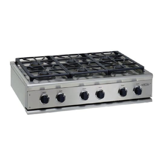
INTRODUCTION DCS Professional Cooktops have a number of features. These features vary with each model configu- ration. All models feature a minimum of 4 surface burners, with the option of up to 6 surface burners on all models. All of the 48" and 36" Cooktops feature the possibility of various grill and griddle combinations. -
Page 5: Models
MODELS 48” CS COOKTOP MODELS CS-484GG CS-486GL CS-486GD CS-485GD 36” CS COOKTOP MODELS CS-366 CS-364GL CS-364GD... -
Page 6: Planning The Installation
PLANNING THE INSTALLATION RECOMMENDED INSTALLATION INSTRUCTION (If installing a full backguard with the cooktop) A) Vent Hood B) Backguard System C) Cooktop 1) Locate cooktop according to cooktop installation instructions. 2) Measure distance from counter surface to top of trim on cooktop adding 1/8” for backguard clearance. -
Page 7: Unpacking And Handling
UNPACKING AND HANDLING STEP 1: MOVING AND PLACING THE COOKTOP NOTE: If a solid side cabinet wall exists on one or both sides, you will need to notch the front corner of the cabinet to match the counter top notch and to provide clearance for the cooktop front (see page 8). -
Page 8: Ventilation Requirements
VENTILATION REQUIREMENTS STEP 2: A suitable exhaust hood must be installed above the cooktop. The following chart indicates the minimum blower capacity recommended for hood ventilation. VENTILATION STANDARD COUNTER ISLAND UNIT INSTALLATION INSTALLATION RECOMMENDATIONS RECOMMENDATIONS HOOD (24" Deep x Unit Width) (30"... -
Page 9: Cabinet Preparation
CABINET PREPARATION STEP 3: 1) To ensure professional results, the cabinet and countertop openings should be prepared by a qualified cabinet worker. We recommend having the cooktop available before cutting the opening for more precise dimension verification. 2) The clearances shown in Fig. 5 pg. 10 are required for all types of backguard installations. 3) The cooktop is designed to hang from the countertop from its side flanges. - Page 10 CABINET PREPARATION STEP 3: (CONTINUED) 6) Cut the openings for the following installation: Standard counter top installation, see Fig. 5A Deep counter or island installation, see Fig. 5B NOTE: If the deck is used, the sides or bottom of Front projects outward as shown Front projects outward as shown the cutout may be solid combustible or from standard depth cabinet.
-
Page 11: Cabinet Preparation
CABINET PREPARATION 26-1/2" Countertop level 8-7/16" 1/2" 5/8" 3" To Center Line of Gas Inlet 22-3/4" 1/2" 23-1/4" 2-1/2" Cabinet face for installation with projecting control panel Cabinet face for installation with flush control panel Fig. 4 STANDARD INSTALLATION ISLAND INSTALLATION 26"... -
Page 12: Backguard Installation
BACKGUARD INSTALLATION STEP 4: Wall Mount Full Backguard BACKGUARD KITS: (Model #’s BGC-3030, BGC-3036, BGC-3048) The backguard is located as shown in Fig. 6. Secure the backguard to the wall behind the cooktop. Wall Mount Low Backguard Specific instructions for installation of the (Model #’s BGC-1230, full backguard or low backguard can be BGC-1236, BGC-1248) -
Page 13: Electrical / Gas Connections
ELECTRICAL / GAS CONNECTIONS STEP 5: Receptacle Box ELECTRICAL CONNECTIONS Receptacle Box Cover Plate Cover Plate Power requirements Cooktop: Three Three Prong Plug Prong 120 VAC, 60 Hz., single phase 15 Amp circuit. Plug Always disconnect electric supply cord from the wall outlet or service disconnect before servicing this appliance. -
Page 14: Hook-Up To Gas Supply
HOOK-UP TO GAS SUPPLY STEP 6: Flex Line To Cooktop Flex Line to Cooktop HOOK-UP A manual valve must be installed external to Manual Shut-Off Manual Shut-Off the appliance, in an accessible location from Valve must be Valve must be the front for the purpose of shutting off the Easily Accessible Easily Accessible... -
Page 15: Test And Adjustments
TEST AND ADJUSTMENTS STEP 7: CAUTION: For warranty coverage, DCS requires that burner adjustments be made by a qualified technician at the time of installation. Extreme care should be used when adjustments are made after installation. Improper or lack of adjustments will void your warranty. -
Page 16: Installer Final Checklist
INSTALLER FINAL CHECKLIST GENERAL Placement of unit. Specified clearance maintained to cabinet surfaces. Unit Level - front to back, side to side. All packaging material and tie straps removed, drip pans clean and empty. Backguard attached if there is less than 12" clearance above the cooking surface to combustibles behind unit. -
Page 17: Wiring Diagrams / Schematics
CS-36/48 WIRING DIAGRAM 17473-01. Rev. A 08/02... -
Page 18: Cs Cooktop 36" / 48"Wiring Schematic
CS-36/48 SCHEMATIC 17473-02. Rev. A 08/02... -
Page 19: Cs Cooktop 485 Wiring Diagram
CS-485 WIRING DIAGRAM 17473-03. Rev. A 08/02... -
Page 20: Cs Cooktop 485 Wiring Schematic
CS-485 SCHEMATIC 17473-04. Rev. A 08/02... -
Page 21: How To Obtain Service
HOW TO OBTAIN SERVICE For warranty service, contact DCS Customer Service at (888) 281-5698. Before you call, please have the following information ready: Model Number Serial Number Date of installation A brief description of the problem Your satisfaction is of the utmost importance to us. If a problem cannot be resolved to your... -
Page 22: Warranty
DCS to be defective. Replacement will be F.O.B. DCS, and DCS will not be liable for any transportation costs, labor costs, or export duties. This warranty shall not apply, nor can we assume responsibility for damage that might... - Page 23 NOTES...
- Page 24 NOTES...
- Page 25 NOTES...
- Page 26 5800 Skylab Road, Huntington Beach, CA 92647 Tel: 714.372.7000 • Fax: 714.372.7001 Customer Service: (888) 281-5698 www.dcsappliances.com As product improvement is an ongoing process at DCS, we reserve the right to change specifications or design without notice. P/N 17526 Rev. B...
Need help?
Do you have a question about the CS-364GD and is the answer not in the manual?
Questions and answers