
Related Manuals for DCS CT-365BL


Summary of Contents for DCS CT-365BL
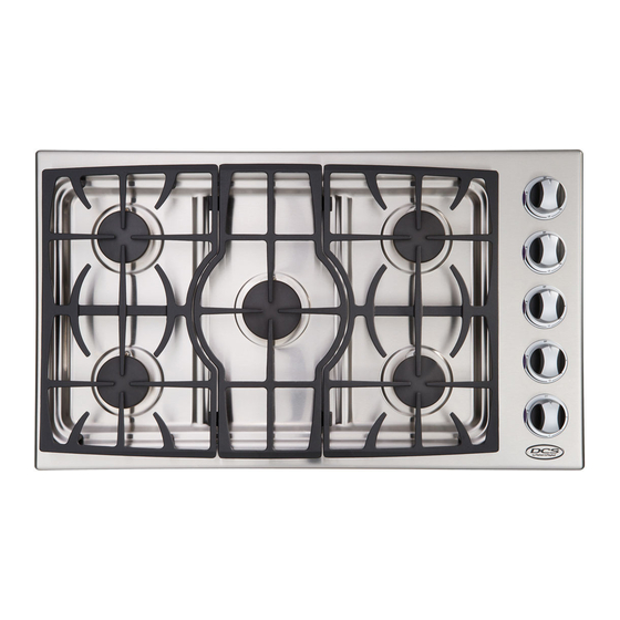
- Page 1 Dynamic Cooking Systems, Inc. PROFESSIONAL 5 BURNER 36" DROP-IN COOKTOP Use and Care Guide Models: CT -365SS CT -365BK CT -365WT CT -365GN CT -365BL...
-
Page 2: A Message T O Ou R Custome Rs
A Message T o Ou r Custome rs Thank you for selecting this DCS Professional Drop-In Cooktop. Because of this appliance’s unique features we have developed this Use and Care Guide. It contains valuable information on how to properly operate and maintain your new appliance for years of safe and enjoyable cooking. -
Page 3: Table Of Contents
Cooking Utensils ...6 Burners ...7 Electronic Igniters...7 Burner Efficiency...8 Flame Height...8 Burner Grates ...8 CARE AND MAINTENANCE Cleaning the Cooktop...9 Cleaning the Burner Grates...9 Cleaning the Burners ...10 Cleaning the Igniters...10 PROPER VENTILATION REQUIREMENTS INSTALLATION INSTRUCTIONS Preparing for the Installation...12 Cabinet Preparation ...13... -
Page 4: Safety Practices And Precautions
Safety Practices & Precautions When properly cared for, your new DCS Appliance has been designed to be a safe, reliable cooking appliance.When using this restaurant caliber appliance, use it with extreme care, as this type appliance provides intense heat and can increase the accident potential. Basic safety precautions must be followed when using kitchen appliances, including the following: •... - Page 5 Some synthetic fabrics are highly flammable and should not be worn while cooking. • Do not use aluminum foil to line any part of the cooktop. Using a foil liner could result in a fire hazard.
- Page 6 Safety Practices & Precautions • Clean the ventilator hood and filters above the cooktop frequently so grease from cooking vapor does not accumulate. • Turn the ventilator OFF in case of fire or when intentionally “flaming” liquor or other spirits on the cooktop.The blower, if in operation, could unsafely spread the flames.
-
Page 7: Cooktop Use
Cooktop Use CAUTION: For warranty coverage, DCS requires that burner adjustments be made by a qualified technician at the time of installation. Extreme care should be used when adjustments are made after installation. Improper or lack of adjustments will void your warranty. -
Page 8: Burners
Your cooktop is equipped with 4 burners rated at 11,000 Btu/hr, and one HI-output burner rated at 17,500 Btu/hr. Your new Drop-In Cooktop has exceptionally low simmer capabilities. -
Page 9: Burner Efficiency
The cast iron burner grates are fully porcelain coated for long life and rust prevention. Hi-Temperature cushions allow the grate to rest softly on the cooktop without scratching.The grates are designed for easy sliding of pots across the grate tops.They were designed in interlocking sections to make them easier to remove and clean. -
Page 10: Care And Maintenance
Once the grates are cool they may be wiped clean while on the cooktop using hot soapy water, then rinsed and wiped dry or they may be placed in the dishwasher for easy cleaning. -
Page 11: Cleaning The Burners
Be certain all burner knobs are in the OFF position before attempting to clean the igniters. Gently wipe with a water dampened cotton swab and be careful not to damage the igniter. COOKTOP BURNER Brass Port Ring Locating Pin Locating... -
Page 12: Proper Ventilation Requirements
36" COOKTOP 600 CFM min. 36" Min. clearance to combustible surface from above the Cooktop Surface 18" Min. clearance to combustible surface from side of cooktop outer edge counter top level VENT HOOD 3O" Min. clearance to WALL non-combustible above cooking... -
Page 13: Installation Instructions
Step 5: Square the cooktop to the cutout and install the (4) retaining brackets onto the 8 holes located at the bottom of the unit, (See Figure 1 below). Step 6: Tighten the 4 preloaded screws which will keep the unit secured, Do Not Over-tighten (See Figure 2 detail below). -
Page 14: Cabinet Preparation
Use the cutout dimension information in the figures below for your installation.When preparing for installation, it is critical that the cabinet cutout matches the cutout dimensions provided for the cooktop for a good fit. See illustrations below for specifications. -
Page 15: Gas Hook Up
Pressure Inches W.C.: 10.0”-LPG/4.0”-Natural Gas Verify the type of gas supplied to the location.The cooktop is shipped from the factory set up for Natural Gas and can be modified for LPG. A manual valve must be installed external to the appliance, in an accessible location from the front for the purpose of shutting off the gas supply. -
Page 16: Power Requirements
Installation Inst ructions POWER REQUIREMENTS: 120 VAC, 60 Hz., single phase. CT-365: 0.10 Amp. Max. (Use 15 Amp. Circuit minimum) • Always disconnect the electric supply cord from the wall outlet or service disconnect before servicing this appliance. • Observe all governing codes and ordinances when grounding, in the absence of which, observe National Electrical Code ANSI/NFPA No. -
Page 17: Installer Final Checklist
Installe r Final Checklist GENERAL Placement of Unit. Specified clearance maintained to cabinet surfaces. Unit Level- front to back, side to side. All packaging material and tie straps removed. ELECTRICAL: Receptacle with 15 ampere current protection is provided for service cord connection. -
Page 18: Product Measurement Specifications
Product Measu rement Specifications To be sure that the CUTOUT for the cooktop is correct in dimensions and to insure a clean installation REFER TO PAGE 12 for Cabinet Preparation and CUTOUT specifications. Top View 21" 36" Front View 34-1/2"... -
Page 19: Wiring Diagram
Wi ring Diagram... -
Page 20: Length Of Warranty
All repair labor and parts found to be defective due to materials or workmanship for one full year from date of purchase. Service must be provided by Authorized Factory Agent during normal working hours. DCS WILL NOT COVER: • Installation or start-up. -
Page 21: How To Obtain Service
Se rvice HOW TO OBTAIN SERVICE: For warranty service, contact DCS Customer Service at (888) 281-5698. Before you call, please have the following information ready: • Model Number • Serial Number • Date of installation • A brief description of the problem Your satisfaction is of the utmost importance to us. - Page 22 Tel: (714) 372-7000 Fax: (714) 372-7001 Parts/Customer Service: (888) 281-5698 www.dcsappliances.com As product improvement is an ongoing process at DCS, we reserve the right to change specifications or design without notice. Part No. 17423 Rev A Litho in USA 8/2001...
Need help?
Do you have a question about the CT-365BL and is the answer not in the manual?
Questions and answers