Table of Contents
Advertisement
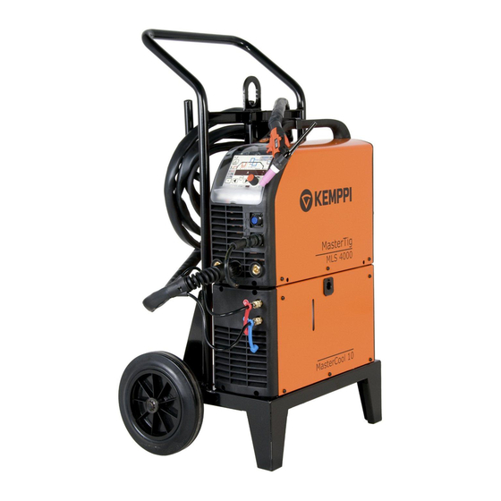
Master MLS™
MasterTig MLS™
MasterCool™
2500, 3500
3000, 4000
10
Operating manual • English
Gebrauchsanweisung • Deutsch
Gebruiksaanwijzing • Nederlands
Manuel d'utilisation • Français
Manual de instrucciones • Español
Инструкции по эксплуатации • По-русски
Manual de utilização • Português
Käyttöohje • Suomi
Bruksanvisning • Svenska
Bruksanvisning • Norsk
Brugsanvisning • Dansk
Instrukcja obsługi • Polski
操作手册 • 中文
Manuale d'uso • Italiano
EN
FI
SV
NO
DA
DE
NL
FR
ES
PL
RU
ZH
PT
IT
Advertisement
Table of Contents

Related Manuals for Kemppi Master MLS 2500


Summary of Contents for Kemppi Master MLS 2500
- Page 1 Master MLS™ 2500, 3500 MasterTig MLS™ 3000, 4000 MasterCool™ Operating manual • English Käyttöohje • Suomi Bruksanvisning • Svenska Bruksanvisning • Norsk Brugsanvisning • Dansk Gebrauchsanweisung • Deutsch Gebruiksaanwijzing • Nederlands Manuel d’utilisation • Français Manual de instrucciones • Español Instrukcja obsługi •...
- Page 3 OperaTing ManuaL english...
-
Page 4: Table Of Contents
COnTenTS preFaCe ..........................General . -
Page 5: Preface
This operating manual contains important information on the use, maintenance and safety of your Kemppi product. The technical specifications of the equipment can be found at the end of the manual. Please read the manual carefully before using the equipment for the first time. For your own safety and that of your working environment, pay particular attention to the safety instructions in the manual. -
Page 6: Installation
inSTaLLaTiOn reMOvaL FrOM paCkaging The equipment is packed in durable packages designed especially for it. However, it is necessary to check the equipment before using it to make sure that the equipment or any part of it has not got damaged during transportation. Also check that the delivery corresponds to your order and that you have received all necessary instructions for installing and operating the equipment. -
Page 7: Installation Of The Panel
inSTaLLaTiOn OF THe paneL Fasten the cable connectors of the function panel to the power source (2 pieces). Place the bottom edge of the panel behind the securing clips on the machine. Remove the fixing pin from the top edge with, for example, a screwdriver. Then gently push the upper part of the panel into place. -
Page 8: Welding Cable Connections
Cooling liquid is injurious! Avoid also contact with skin or eyes. In case of injury, seek for NOTE! medical advice. Cooling unit MasterCool 10 together with TIG torch of Kemppi’s TTC-W range enables TIG welding with water-cooled torch. The cooling unit is installed beneath the power source with screws. Electrical connections are on the bottom of power source. -
Page 9: Shield Gas
8 – 10 l/min. If the gas flow is not suitable the welded joint will be porous. Spark ignition becomes more difficult if the gas flow is too high. Contact your local Kemppi dealer for choosing gas and equipment. -
Page 10: Installation Of Gas Bottle
2.10.1 installation of gas bottle parts of gas flow regulator Gas bottle valve Pressure regulation screw Connecting nut Hose spindle Jacket nut Gas bottle pressure meter Gas hose pressure meter Always fasten gas bottle properly in vertical position in a special holder on the wall or on a NOTE! carriage. -
Page 11: Tig Welding
Before welding starts, welding settings suitable for the work piece are chosen with the function panel. See 3.1. Welding processes. The Kemppi Multi Logic System, MLS™, allows you to select from different function panels according to your welding application. MEL and MEX panels are designed for MMA welding. - Page 12 MMa welding panel MeL Remote/local control switch Welding current potentiometer Contact TIG welding MMA welding Arc force Hot start Digital display and amperage/voltage switch Welding current table...
- Page 13 MMa welding panel MeX MEX panel is available separately. The functions of MEX panel are described in the operating manual delivered with the panel. Indicator lights: Main switch, overheating, wrong mains voltage MODE button for welding method selection: MMA, contact TIG, carbon arc gouging, broken Selection of electrode type Potentiometer for regulation of welding current and other parameters Displays of welding current and other parameters (A, V, s, mm)
- Page 14 Tig welding panel MTL – basic functions Selection of MMA welding Selection of arc force (MMA) and pedal low/high (minimum and maximum welding current) displays and regulation (TIG welding) Selection of hot start (MMA) and gas test (TIG welding) Selection of TIG welding, 4T and 2T functions of torch switch Selection of HF/contact and water fill function Selection of panel, foot pedal and remote control Selection of welding parameters...
- Page 15 3. Hot start When pressing the hot start button, you will see on the display the numerical value corresponding to the MMA hot start pulse. You can adjust the value by turning the potentiometer. In TIG mode you can select gas test function. 4.
- Page 16 Tig welding panel MTX – pulsed Tig functions 4T-LOG Selection for spot, synergetic quick pulse and long pulse Search arc 10 – 80 % of welding current Pulse current 10 A – max. Pulse ratio 10 – 70 % of pulse time Frequency 0.2 –...
- Page 17 Long pulse Long pulse method gives you the possibility to adjust all pulse parameters (pulsing frequency, pulse ratio, pulse current and pause current). You can also adjust the welding current, in which case you receive a new pulse current value. Pulse ratio and pause current percentage remain constant.
-
Page 18: Saving Welding Settings (Mtm)
Tig welding panel MTM – pulsed Tig and MiniLOg function with memory Minilog Selection of memory function Selection of channel in memory function Minilog 10 – 90 % of welding current SAVE Minilog operation When torch switch is pressed gas flow starts. When you release the switch current goes to search arc. -
Page 19: Adopting The Saved Settings
If the saved settings need to be adjusted the led has to be moved from ON to SET position in order to select parameters. Press the SAVE button. It is also possible to save the currently used parameters by pressing SET when the memory function is in OFF state (no lights on). Channel is cleared if MEMORY and CH buttons are pressed simultaneously in SET mode. -
Page 20: Foot Pedal Control R11F
3.2.7 Foot pedal control r11F First read under ”3.2.2.4. TIG welding panel MTL” point ”6. Remote control” for installing the remote control ready for operation. Foot pedal R11F is used in TIG welding, and its control range is adjustable. The minimum value of control range is set with the panel potentiometer when the pedal is not pressed, display shows ”LO”. -
Page 21: Service Contract
The owner of the equipment is obliged to deliver a decommissioned unit to a regional collection centre, per the instructions of local authorities or a Kemppi representative. By applying this European Directive you will improve the environment and human health. -
Page 22: Ordering Numbers
Ordering nuMberS Master MLS™ 2500 6104250 Welding cable 35 mm² 2.5 m 6184301 Earth cable 25 mm² 2.5 m 6184311 Electric plug 16 A 5-poles 9770812 Master MLS™ 3500 6104350 Welding cable 50 mm² 2.5 m 6184501 Earth cable 50 mm² 2.5 m 6184511 Electric plug 16 A... - Page 23 Panels 6106000 6106010 6116000 TIG 4T-LOG 6116005 TIG MINILOG 6116015 TIG MEMORY 6116010 Optional device TIG torch controls RTC 10 6185477 RTC 20 6185478 Remote control R 10 6185409 R11T 6185442 R11F 6185407 Transport unit T100 6185250 T110 6185251 T130 6185222 T200 6185258...
-
Page 24: Technical Data
TeCHniCaL daTa Power source Master MLS™ 2500 Connection voltage 3~50/60 Hz 400V -15 %...+20 % Rated power at max. current 40% ED MMA 9.4 kVA 30% ED TIG 8.4 kVA Connection cable HO7RN-F 4G1.5(5m) Fuse (delayed) 10 A Duty cycle 40 °C 10 A/20.5 V...250 A/30.0 V 5 A/10.0 V...300 A/22.0 V Max welding voltage... - Page 25 Power source Mastertig MLS™ 3000 Connection voltage 3~ 50/60 Hz 400V –15%…+20% Rated power at max. current 30% ED TIG 8.4 kVA 40% ED MMA 9.4 kVA Connection cable HO7RN-F 4G1.5(5m) Fuse (delayed) 10 A Duty cycle 40 °C 10 A/20.5 V...250 A/30.0 V 5 A/10.0 V...300 A/22.0 V Max welding voltage 36 V / 250 A...
- Page 26 Cooling unit (TIG-welding) MasterCool 10 Operating voltage 400V –15%…+20% Connection capacity 100 % ED 250 W Cooling power 1 kW Start pressure, max 0.4 MPa Cooling liquid 20% – 40 % etanol-water Tank volume External dimensions LxWxH 500x180x260 mm Weight 11 kg Power source and cooling unit Operating temperature range...
- Page 28 78681 EPONE CEDEX myynti.fi@kemppi.com info.ru@kemppi.com FRANCE Tel +33 1 30 90 04 40 KEMPPI SVERIGE AB KEMPPI, TRADING (BEIJING) COMPANY, Telefax +33 1 30 90 04 45 LIMITED Box 717 sales.fr@kemppi.com Room 420, 3 Zone, Building B, S-194 27 UPPLANDS VÄSBY No.12 Hongda North Street,...
Need help?
Do you have a question about the Master MLS 2500 and is the answer not in the manual?
Questions and answers