Table of Contents
Advertisement
Quick Links
Advertisement
Table of Contents

Related Manuals for Extraflame INSERTO COMFORT MINI


Summary of Contents for Extraflame INSERTO COMFORT MINI
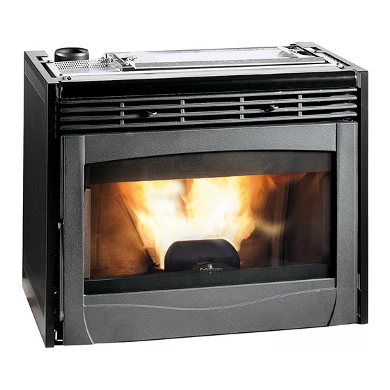
- Page 1 PELLET STOVES Instruction Manual INSERTO COMFORT MINI...
- Page 2 Page 2...
- Page 3 Congratulations! You are now the owner of an EXTRAFLAME stove! The EXTRAFLAME pellet stove is an ideal heating solution. It utilises the most advanced technology and is manufactured to the highest standards with a contemporary design, allowing you to enjoy the ambience and warmth of a natural flame in complete safety.
-
Page 4: Table Of Contents
Contents PRECAUTIONS AND SAFETY TECHNICAL SPECIFICATIONS WHAT ARE PELLETS? Pellet storage SAFETY DEVICES Warm air blower breakdown Fume exhauster breakdown Pellet feed motor breakdown Lighting failure Temporary power failure Electrical safety Exhaust system safety Pellet overheating safety ASSEMBLY AND INSTALLATION INSTRUCTIONS Glossary Installation 5.2.1... -
Page 5: Precautions And Safety
Extraflame S.p.A. Do not touch the stove if you are bare-footed may not be held responsible in the or if parts of your body are wet or damp. -
Page 6: Technical Specifications
2. TECHNICAL SPECIFICATIONS Unit of Mini Comfort measurement Insert Height 1522 Width Depth Weight Exhaust pipe diameter Max. heating volume m³ Total power (heating power) kW/h 3.0 - 9.4 Water heating power kW/h Pellet consumption per hour kg/h 0.8 - 2.0 Absorbed electrical power 25 - 100 Lighting power... -
Page 7: What Are Pellets
For this reason, pellets do not need to be seasoned to obtain a sufficient heating yield. Pellet diameters range from a minimum of 5 mm to a maximum of 8 mm, though Extraflame recommends using 6 mm pellets. Page 7... -
Page 8: Safety Devices
4. SAFETY DEVICES 4.1 Warm air blower breakdown If the blower stops for any reason, the stove automatically shuts down to prevent overheating. 4.2 Fume exhauster breakdown If the exhauster stops, the electronic unit immediately prevents pellet feeding. 4.3 Pellet feed motor breakdown If the motor stops, the stove continues to operate until the minimum cooling level is reached. -
Page 9: Assembly And Installation Instructions
5. ASSEMBLY AND INSTALLATION INSTRUCTIONS The installation must comply with: UNI 10683 (2005) heat generators fed with wood and other solid fuels: installation. The chimneys must comply with: UNI 9731 (1990) chimneys: classification according to thermal resistance. UNI 9615 (1995) calculation of the internal dimensions of the chimneys with single connection. UNI 7129 point 4.3.3 provisions, local rules and prescriptions of the fire brigade. -
Page 10: Installation
EXHAUST VENTING SYSTEM A system for fume exhaust venting that is independent from the appliance, composed of a pipe or channel, chimney or single flue, and chimney cap. FORCED DRAUGHT Air circulation by means of a fan driven by an electric motor. NATURAL DRAUGHT Draught resulting in a chimney/flue due to the difference in the volume mass existing between the (hot) fumes and the surrounding atmospheric air, without any mechanical suction aid installed... -
Page 11: Connection To The Exhaust Venting System
Flue Inspection For heat generating devices equipped with an electric exhaust fan, i.e. all products made by Extraflame, it is necessary to observe the following instructions: Horizontal sections must have a minimum slope of 3% upwards. • The length of the horizontal section must be as short as possible, and in any case no •... -
Page 12: Chimney Or Single Flue
It is forbidden to run other air feed channels or piping for utilities inside the exhaust channels, even if they are oversized. It is also forbidden to fit manual draught adjustment devices on the forced draught appliance. 5.2.2 Chimney or single flue The chimney or flue must meet the following requirements: - be airtight to combustion products, waterproof and properly insulated according to the usage conditions;... - Page 13 The exhaust duct should be equipped with a chamber for the collection of solid materials and any condensates located below the mouth of the exhaust channel, so that it is easy to open and inspect from the airtight hatch. Windproof chimney Maximum 3 m 3 –...
-
Page 14: Connection To The Flue And Combustion Product Exhaust Venting
5.2.3 Connection to the flue and combustion product exhaust venting The connection between the appliance and the flue must only receive the discharge from a single heat generator. Direct discharge towards enclosed areas, even when roofless, is forbidden. Direct discharge of combustion products must take place on the roof and the exhaust duct must have the features set forth in the section “Chimney or single flue”... -
Page 15: Connection To External Air Intakes
In addition, no grating or similar device should be positioned. (Extraflame S.p.A. suggests creating an air intake directly communicating with the installation room, even if air is collected from outside by means of a pipe). -
Page 16: Mini Comfort Installation
6. MINI COMFORT INSERT INSTALLATION The Maxi Comfort insert is supplied with a metal sliding base that enables it to be installed in an existing fireplace. The base allows you to slide out the insert easily for maintenance and cleaning at the end of the year. - Page 17 N.B. The insert must stand at least 1 cm above the marble fire top of the facing. Installation with pedestal (optional) Description of components: Maxi Comfort insert • Pedestal adjustable in height • Side feeding hopper • Adjustable hopper support •...
- Page 18 Extracting the insert The Comfort insert has to be extracted to carry out routine maintenance (cleaning the ash pipe at the end of the year) or special servicing (replacing mechanical parts in the event of damage). N.B. These operations must be carried out by an authorized technician, with the stove switched off and the plug disconnected.
- Page 19 Air circulation ducts To ensure correct operation, it is necessary to create air intakes at the top of the fireplace. These can be made in the sides of the hood or on the front. The following measurements must be respected: Air intakes made on both sides of the fireplace: Minimum measurement required 200 cm per side.
- Page 20 Warm convection air It is necessary provide an outlet for the heat accumulated in the facing to prevent excessive overheating of the insert. 5 cm Forced ventilation The blower conveys the heat produced in the insert into the room. Air intake from the room To enable air circulation, it is necessary to have an air intake point, preferably at the lower part of the structure, for better...
-
Page 21: Remote Control Operation
6. Power up the stove. 7. The stove will emit two acoustic signals: between the first and the second, press button 1 for 1 second. At this point, the display will show “EXTRAFLAME”. General characteristics The visual interface is given on an LCD display with •... -
Page 22: Display
Buttons 4 and 5 – Parameter increase/decrease On the main screen. These buttons are used for regulating the operating power of the stove from a minimum setting of 1 to a maximum of 5; this value is shown on the upper display. During modification of the user parameters, the buttons are used for increasing/decreasing the value of the parameter, which is shown on the first line of the display. -
Page 23: Using The Insert
8. USING THE STOVE The stove you have purchased uses pellets as fuel. This type of material is produced from natural waste from woodworking. By means of a special process, which does not require the use of any binders or additives, the shavings are compressed in industrial machines under high pressure and become solid wooden pellets. -
Page 24: Insert Operation
10. INSERT OPERATION 10.1 Normal operation Once the stove is lit, you can adjust the heat setting using buttons 4 and 5. Pressing button 4 decreases the heat setting and hourly pellet consumption; pressing 5 increases them. In addition to the feed rate, the room temperature can be set directly from the control panel. The stove adjusts itself automatically in relation to the warm air ventilation. -
Page 25: User Menus
11. USER MENUS The table below shows the various menus available to the user: Menu Description 1 Set temperature Menu for setting the temperature Set clock Menu for setting the current day and time Set timer Menu for setting the switch-on/off programmes Day/Night Menu for day/night temperature function Pellet Feed... -
Page 26: Set Timer
When you have entered the programming function, the display will show the following parameters: Parameter 1 CLOCK DAY Used for setting the following values: “day1”… “day7” use buttons 4 and 5 to set the current day of the week. When the current day has been set, the weekly programmer function is automatically enabled. To confirm and continue with programming, press the menu 2 button. - Page 27 To confirm and continue with programming, press the menu 2 button. To return to the previous parameter, press the menu 1 button. Parameter 3 DAYS ON 1 Used for setting which days of the week to enable/disenable the time period set. The procedure is as follows: a.
-
Page 28: Day/Night
TO ENABLE/DISENABLE the weekly programmer, follow the procedure described at parameter Set Clock Menu. 1 of the Note: When the programmer is enabled, the corresponding LED lights up on the display (see Table of Display Messages Manual controls always have priority over the programming. 11.4 DAY/NIGHT MENU The day/night temperature function makes it possible to switch the stove on/off automatically based on two selected temperatures. -
Page 29: Pellet Feed
N.B.: This only occurs when the stove is in “doff” status and not “SPENTO” (OFF) status. Manual controls always have priority over the programming. 11.5 Pellet Feed Menu If the stove has operating problems due to the quantity of pellets, you can adjust the pellet feed directly from the remote control. -
Page 30: Language
Adjustment table Increase the percentage by 5 percent and try the stove with this new setting LACK OF for at least half an hour. If the problem is reduced but not resolved, increase PELLETS by a further 5 percent. Repeat this process until the problem is resolved. If the problem cannot be resolved, contact the service centre. -
Page 31: Table Of Display Messages
11.7 Table of display messages INDICATIONS Display Cause Solution Message When the stove has just been shut down (normal An attempt is made to switch on a shutdown or caused by an alarm situation), you have to ATTESA stove again when it has just been wait until it is completely cold and then clean the burn PULIZIA shut down (normal shutdown or... - Page 32 ALARMS Display Cause Solution Message This indicator lights up when one of the alarms described below progress accompanied Indicates the presence of an alarm corresponding indication on display D1. To reset the alarm, press button 1 and hold for three seconds when the stove is completely cold.
-
Page 33: External Thermostats
INDICATOR LIGHTS LED indicator Meaning Description light Weekly programmer This LED is on/off when is on/ off. Weekly Programmer function For all the settings regarding this function, see the section Weekly programmer This LED is on/off when the room temperature is lower/higher than the temperature set. -
Page 34: Installing A Mechanical Thermostat (Optional)
12.2 Installing a mechanical thermostat (optional) N.B.: Installation must be carried out by an authorized technician. 1. Switch off the appliance using the master switch on the back of the stove. 2. Disconnect the plug from the power outlet. 3. Referring to the electrical wiring diagram, connect the two thermostat wires to the respective terminals on the back side of the stove, one red and one black. -
Page 35: Wiring Diagram
13. WIRING DIAGRAM Page 35... -
Page 36: Cleaning
14. CLEANING 1. CLEANING THE BURN POT The burn pot must be cleaned every day. To do so: Remove the burn pot form its compartment and • clean the holes using the poker provided (see Fig.1). Remove the ash from the burn pot using a vacuum •... -
Page 37: Chimney Connection
the end to remove ash completely (see Fig. 8). When finished, reposition the removable cast iron piece with a motion exactly opposite the one used for removing it. Once the firewall is positioned, turn the screw-bolt 180° to put it back in its original position. -
Page 38: Burn Pot Partition
15. BURN POT PARTITION The Mini Comfort insert has a partition fixed to the burn pot by a screw, which makes it possible to optimise the stove combustion processes. WARNING!! Removing the burn pot partition can jeopardise stove safety and immediately voids the warranty. -
Page 39: Warranty
EXTRAFLAME S.p.A. guarantees this product for a period of 2 (two) years from the date of purchase against manufacturing and material defects. The responsibility of EXTRAFLAME S.p.A. is limited to the supply of the appliance, which must be properly installed following the instructions contained in the booklets provided with the product and respecting the laws in force. - Page 40 The service under warranty involves repair of the product completely free of charge as per the laws in force. RESPONSIBILITY EXTRAFLAME S.p.A. shall not be liable for any direct or indirect damage caused by or depending on the product. COMPETENT COURT For any controversy, the competent court shall be the court of Vicenza, Italy.
-
Page 41: Quality Control
17. QUALITY CONTROL Model Serial no. Tests carried out - automatic lighting - combustion air motor - convection air motor - appearance - packing/technical data label Stamp Technician’s signature _______________ Date of purchase ___________________ manufacturer within 8 days of the date of purchase . Cut out and send to the Name Surname... - Page 42 Notes Page 42...
- Page 43 Notes Page 43...
- Page 44 PELLET STOVES EXTRAFLAME S.p.A. Via Dell’Artigianato, 10 36030 MONTECCHIO PRECALCINO Vicenza - ITALY Tel. 0445/865911 Fax 0445/865912 http://www.extraflame.com E-mail: info@extraflame.com 004275115 REV 003 21.03.2006 Manuale d’uso e manutenzione I.C. Mini uk Page 44...
Need help?
Do you have a question about the INSERTO COMFORT MINI and is the answer not in the manual?
Questions and answers