
Related Manuals for Extraflame Ecologica Idro


Summary of Contents for Extraflame Ecologica Idro
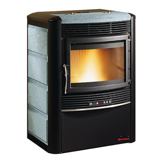
- Page 1 PELLET STOVES Instruction Manual Ecologica Idro Read these instructions carefully before installation, use and maintenance. The instruction booklet is an integral part of the product.
- Page 2 Congratulations! You are now the owner of an EXTRAFLAME stove! The EXTRAFLAME pellet stove is an ideal heating solution. It utilises the most advanced technology and is manufactured to the highest standards with a contemporary design, allowing you to enjoy the ambience and warmth of a natural flame in complete safety.
-
Page 3: Table Of Contents
Contents WARNINGS AND SAFETY TECHNICAL SPECIFICATIONS WHAT ARE PELLETS? Pellet storage Pellet loading SAFETY DEVICES Breakdown of hot air distribution fan Breakdown of flue gas extractor Breakdown of pellet load motor Failed ignition Temporary power cut Electrical safety device Flue gas exhaust safety device Pellet temperature safety device System pressure safety device 4.10... -
Page 4: Warnings And Safety
The air vents are critical for correct combustion. Extraflame S.p.A. held responsible in the event of failure to observe Keep the packaging materials out of the reach of these precautions. -
Page 5: Technical Specifications
2. TECHNICAL SPECIFICATIONS Valore Features Unit Value Weight Height Width Depth Flue gas exhaust pipe diameter Air extraction pipe diameter Max. overall thermal power Max. useful thermal power 12.5 - output air power - output water power 11.5 Min. useful thermal power - output air power - output water power Min. - Page 6 Page 6...
-
Page 7: What Are Pellets
DIN plus 51731 • UNI CEN/TS 14961 • Extraflame recommends always using 6 mm pellets for its products. 3.1 Pellet storage To guarantee problem-free combustion, the pellets must be stored in a dry place. 3.2 Pellet loading To load the pellets, open the tank cover positioned on the upper part of the stove and empty the bag of pellets, paying attention not to let them escape. -
Page 8: Safety Devices
4. SAFETY DEVICES 4.1 Breakdown of hot air distribution fan If the blower stops for any reason, the stove automatically shuts down to prevent overheating 4.2 Breakdown of flue gas extractor If the extractor stops, the electronic unit immediately prevents pellet feeding. 4.3 Breakdown of pellet load motor If the motor stops, the stove continues to operate until the minimum cooling level is reached. -
Page 9: Installation And Safety Devices
1990), in full respect for the regulations in force, both national and regional, as well as for the instructions given in this manual. Extraflame S.p.A. declines any responsibility for damage to objects and/or persons caused by the system. 4.13 Safety devices for open expansion tank system... -
Page 10: Assembly And Installation Instructions
5. ASSEMBLY AND INSTALLATION INSTRUCTIONS The installation must comply with: UNI 10683 (2005) heat generators fed with wood and other solid fuels: installation. The chimneys must comply with: UNI 9731 (1990) chimneys: classification according to thermal resistance. EN 13384-1 (2006) calculation method of the thermal and fluid-dynamic features of the chimney. UNI 7129 point 4.3.3 provisions, local rules and prescriptions of the fire brigade. -
Page 11: Installation
FLUE GAS VENTING SYSTEM A system for flue gas exhaust venting that is independent from the appliance, composed of a pipe or channel, chimney or single flue, and chimney cap. FORCED DRAUGHT Air circulation by means of a fan driven by an electric motor. NATURAL DRAUGHT Draught resulting in a chimney/flue due to the difference in the volume mass existing between the (hot) fumes and the surrounding atmospheric air, without any mechanical suction aid installed... -
Page 12: Connection To The Flue Gas Evacuation System
Flue Inspection For heat generating devices equipped with an electric exhaust fan, i.e. all products made by Extraflame, it is necessary to observe the following instructions: Horizontal sections must have a minimum slope of 3% upwards. • The length of the horizontal section must be as short as possible, and in any case no •... -
Page 13: Chimney Or Flue
5.2.2 Chimney or single flue The chimney or flue must meet the following requirements: - be sealed to combustion products, waterproof and properly insulated according to the usage conditions; - be made of materials suitable to resist normal mechanical stress, as well as heat and the action of combustion products and any condensates;... - Page 14 Windproof chimney cap Maximum 3 m 3 – 5 % Flue Inspection Inspection Maximum 3 m External insulated duct 45° Inspection Inspection Page 14...
-
Page 15: Connecting The Appliance To The Flue And Evacuation Of Combustion Products
5.2.3 Connecting the appliance to the flue and evacuation of combustion products The flue must receive exhaust from a single heat generator. Direct discharge towards enclosed areas, even when roofless, is forbidden. Direct discharge of combustion products must take place on the roof and the exhaust pipe must “Chimney or single flue”... -
Page 16: Connection To External Air Inlets
In addition, no grating or similar device should be positioned. (Extraflame S.p.A. suggests creating an air intake directly communicating with the installation room, even if air is collected from outside by means of a pipe). Air inflow can also be obtained from a room adjacent to the installation room, provided that the flow can occur freely through permanent openings communicating with the outside. -
Page 17: Control Panel
6. CONTROL PANEL REMOTE CONTROL SENSOR ON/OFF BUTTON The stove can be turned on and off automatically by pressing button 1. AIR TEMPERATURE SETTING Buttons 2 and 3 are used to adjust the room temperature inside the house. OPERATING POWER Buttons 4 and 5 are used to adjust the heating power and warm air ventilation. -
Page 18: Adjusting Current Time
7. CURRENT TIME AND DAY SETTINGS To adjust these parameters follow the procedure below: 1. Disconnect and reconnect the power supply from the stove using the master switch or the power cable. 2. The stove will firstly visualise the microprocessor version (Id_40 or later), “TIME”, “Li 3” and then “OFF”. -
Page 19: Stove Operation
The first time the stove is used, even if the tank is loaded with pellets, it is possible NOTE: that the pellets are not distributed to the combustion chamber for the first 15 minutes because the worm screw for loading the pellets is empty. If the stove has not developed a flame after the fifteen minutes have elapsed, the display shows the message “NO ACC”. -
Page 20: Remote Control
10.3 Remote control The heat setting, the room temperature, and automatic start/stop of the stove can be remote controlled. S = Light that indicates which keys have been pressed. Correspondence of display keys with remote control keys 1 = p3+p5 2 = p2 3 = p3 4 = p4... -
Page 21: Room Thermostat
11. ROOM THERMOSTAT 11.1 Digital thermostat (standard) The stove can control the room temperature by means of a digital thermostat whose function is to lower the heating power to the minimum when a pre-set temperature is reached. 1. When the stove has been started and has entered normal operating mode, a number (e.g. - Page 22 11.2.3 Mechanical thermostat operation in Standby mode (to be used also for remote actuator) The Standby function is used to further reduce pellet consumption by switching off the stove when the desired temperature has been reached. As the temperature drops, the stove will automatically switch on again. 1.
-
Page 23: User Parameters
12. USER PARAMETERS USER PARAMETERS WATER TEMPERATURE ADJUSTMENT Display D1 Display D2 Function 70°C Water temperature adjustment WEEKLY PROGRAMMER Display D1 Display D2 Function Act./ Deact. Weekly programmer 00:00 1st ignition time 00:00 1st switch-off time off 1 Consents for 1 ignition /switch-off for the various days Installer parameter 00:00... - Page 24 setting current day and Before programming this function, you have to set the current time using “ time” in order to provide a reference for the programming function. To access programming press and hold button 3, then press button 5 and then release the 2 buttons at the same time.
- Page 25 Example: Initial value Function button 2 Final value Function button 3 OFF 1 ON 1 and vice versa MONDAY OFF 1 ON 1(period active) Passes to the following day OFF 2 ON 2 and vice versa TUESDAY OFF 2 ON 2(period active) Passes to the following day OFF 3 ON 3 and vice versa...
-
Page 26: Day/Night Temperature Function
Parameter 9 (D2=9(flashing); D1=E.g. “off”) Using buttons 2 or 3 set “off”, which can be found before “00:00”, in order to disable the switching on of the 3 time period. To confirm and continue programming press button 5. To return to the previous parameter press button 4. Parameter A (D2=A(flashing);... - Page 27 When you have exited from the programming, to activate/deactivate the function, press button 4 and hold it down, press button 5, then release both buttons at the same time. The corresponding LED on the control panel will light up/go off (see description in the display messages table).
-
Page 28: Pellet Load Adjustment
12.4 Pellet loading adjustment If the stove has operating problems due to the quantity of pellets, you can adjust the pellet load directly from the control panel. Problems related to the quantity of pellets fall into one of two categories: - LACK OF PELLETS The stove cannot develop a suitable flame, tending to burn very poorly even at high •... -
Page 29: Cleaning
13. CLEANING Maintenance operations guarantee correct functioning of the product through time. The lack of fulfilment of these operations can jeopardise safety of the product. 1. CLEANING THE BRAZIER The brazier must be cleaned daily. Remove the brazier from its container and clean the •... -
Page 30: Connection To The Chimney
6. DOOR, ASH DRAWER AND BRAZIER SEALS The seals ensure that the stove is hermetically sealed and consequently that it operates correctly. The seals should be checked periodically and replaced immediately if worn or damaged. These operations must be carried out by an authorised technician. N.B.: To ensure correct operation, the stove should have general maintenance performed at least once a year by an authorised technician. -
Page 31: Wiring Diagram
14. WIRING DIAGRAM Wiring diagram Page 31... - Page 32 Wiring Diagram Numbering Description Pump power supply terminal Circuit board power supply terminal Flue gas expulsion motor power supply terminal Cross-flow fan power supply terminal Pellet loading geared motor power supply terminal Spark plug power supply terminal Flue gas probe input terminal External thermostat input terminal Room probe input terminal Encoder input terminal...
-
Page 33: Stove Display Message Tables
15. TABLE OF DISPLAY MESSAGES MESSAGES Message Cause Solution Display When the stove has just been shut down (normal shutdown or caused by an alarm situation), you have An attempt has been made to switch on a stove to wait until it is completely cold and then clean the Atte again when it has just been shut down (normal brazier. - Page 34 ALARMS Message Cause Solution Display D1 This indicator lights up when one of the alarms described below is in progress and is accompanied by the corresponding indication on display D1. To reset the alarm, press button 1 and hold for three seconds when the stove Indicates the presence of an alarm is completely cold.
- Page 35 INDICATOR LIGHTS LED indicator Meaning Description light Weekly programmer This LED is on/off when is on/ off. Weekly Programmer function For all the settings regarding this function, see the section Weekly programmer This LED is on/off when the room temperature is lower/higher than the temperature set.
-
Page 36: Warranty
10 (Italy), extends to all components of the stove supplied by Extraflame S.p.A., and includes free repair or replacement of any faulty part of the stove, on condition that: The defect is detected within 2 YEARS of the delivery date and is reported to an Extraflame •... - Page 37 Extraflame S.p.A. is not liable for eventual damage which may be caused, either directly or indirectly, to people, things and pets as the result of not following the instructions indicated in this installation, use and maintenance manual or the current norms related to installation and maintenance of this product.
-
Page 38: Quality Control
17. QUALITY CONTROL Model Serial no. Tests carried out - automatic ignition - combustion air motor - convection air motor - appearance - packing/technical data label Technician’s signature ________________ Stamp Stamp Date of purchase ___________________ Cut out and send to the manufacturer within 15 days of the date of purchase Name Surname Address... -
Page 39: Compatibility With Rohs And Weee Directives
18. COMPATIBILITY WITH RoHS AND WEEE DIRECTIVES European Directives The European Union has approved new Directives with the aim of reducing the potentially hazardous substances in order to reduce risks to health and the environment, as well as guaranteeing the safe disposal of electrical and electronic appliances through re-use, recycling and energetic recovery of the waste. - Page 40 PELLET STOVES EXTRAFLAME S.p.A. Via Dell’Artigianato, 10 36030 MONTECCHIO PRECALCINO Vicenza - ITALY Tel. 0445/865911 Fax 0445/865912 http://www.extraflame.com E-mail: info@extraflame.com Page 40 004275286 REV 006 16.04.2007 Manuale Utente Ecologica Idro...
Need help?
Do you have a question about the Ecologica Idro and is the answer not in the manual?
Questions and answers