
Related Manuals for Extraflame DUCHESSA IDRO


Summary of Contents for Extraflame DUCHESSA IDRO
-
Page 1: User Manual
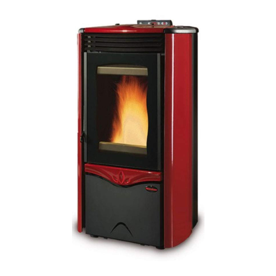
Stufe a Pellet PELLET STOVES User manual DUCHESSA IDRO DUCHESSA IDRO STEEL Read the instructions carefully before installation, use and maintenance. The instruction book is an integral part of the product. - Page 3 Congratulations! You are now the owner of an Extrafl ame stove The Extrafl ame pellet stove is a great heating solution developed from the most advanced technology with top quality machining and modern design, aimed at making you enjoy the fantastic sensation that the heat of a fl ame gives, in complete safety.
-
Page 5: Table Of Contents
Chapter 1 WARNINGS AND SAFETY DEVICES......................7 Chapter 2 TECHNICAL FEATURES ..........................8 DIMA DUCHESSA IDRO .................................9 DIMA DUCHESSA IDRO STEEL ............................10 Chapter 3 WHAT IS THE PELLET? ..........................11 PELLET STORAGE .................................. 11 PELLET FEEDING ................................... 11 Chapter 4 SAFETY DEVICES ............................. - Page 6 COMMISSIONING CHECKS ............................25 FEEDING WATER FEATURES ............................25 FILLING THE PLANT ............................... 25 Chapter 7 PRODUCT FUNCTIONALITY ........................26 CONTROL BOARD ................................. 26 CURRENT DATE AND TIME ADJUSTMENT ........................26 BASIC INSTRUCTIONS ................................. 27 IGNITION ....................................27 WATER TEMPERATURE ADJUSTMENT........................... 28 WORK ......................................
-
Page 7: Warnings And Safety Devices
Chapter 1 WARNINGS AND SAFETY DEVICES The stoves produced by our establishment are built The stove must be serviced at least once a year, with attention to the individual components in a way programming it in advance with the technical to protect both the user and the installer from any after-sales service. -
Page 8: Technical Features
Chapter 2 TECHNICAL FEATURES Duchesssa Duchessa Idro Features U.M. Idro Steel Weight Height 1034 1034 Width Depth Flue exhaust pipe diameter Air intake pipe diameter Max. global heat output 13.1 13.1 Max. useful heat output 12.0 12.0 - useful output power to the air - useful output power to the water 10.8... -
Page 9: Dima Duchessa Idro
Chapter 2 DIMA DUCHESSA IDRO A = AIR INTAKE PIPE Ø 50 mm B = FLUE GAS EXHAUST PIPE Ø 80 mm C = BOILER 3/4 “ FLOW/OUTLET D = BOILER 3/4 “ RETURN/INLET E = 3 BAR 1/2 “ SAFETY DRAIN G = BOILER 3/4 “... -
Page 10: Dima Duchessa Idro Steel
Chapter 2 DIMA DUCHESSA IDRO STEEL A = AIR INTAKE PIPE Ø 50 mm B = FLUE GAS EXHAUST PIPE Ø 80 mm C = BOILER 3/4 “ FLOW/OUTLET D = BOILER 3/4 “ RETURN/INLET E = 3 BAR 1/2 “ SAFETY DRAIN G = BOILER 3/4 “... -
Page 11: Chapter 3 What Is The Pellet
Chapter 3 WHAT IS THE PELLET? Pellets are realised by subjecting wood shavings i.e. the rejects of pure wood (without paint) sawmill, carpenter products and products from other activities connected to working and transforming wood, to very high pressures. This type of fuel is absolutely ecological as no glues are used to hold it together. In fact, the compactness of the pellets is guaranteed through time by a natural substance that is found in wood: lignin. -
Page 12: Chapter 4 Safety Devices
Chapter 4 SAFETY DEVICES FLUE EXHAUST BREAKAGE If the suction device stops, the electronic board immediately blocks the pellet supply. PELLET FEED MOTOR STOP If the motor reducer stops for any reason, the stove goes into alarm mode and the fumes motor continues to function in order to expel all combustion gas until the minimum cooling level is reached. -
Page 13: Water Overheating Safety Via 100° C Bulb
Chapter 4 WATER OVERHEATING SAFETY VIA 100° C BULB When the temperature of the water inside the product is in proximity of 100°C, pellet feeding is blocked. If the bulb trips, restoration of the safety device is manual and must be performed by an authorised technician. The restoration of 100°C safety device is not under warranty unless the after-sales centre can show the presence of a faulty component. - Page 14 Chapter 4 Adjustment automatic circuit breaker switch Automatic circuit breaker switch (block thermostat) Circulation system Expansion system* Safety dissipation system incorporated with the generator with thermal safety valve (self-activated), whenever the appliance does not have a temperature self-adjustment system. The temperature safety sensors must be in place on the machine at a distance no greater than 30 cm from the fl ow connection.
- Page 15 Chapter 4 Door micro switch Rearm of the tank bulb 85°C Rearm water bulb 100°C SAFETY DEVICES...
-
Page 16: Assembly And Installation Instructions
Chapter 5 ASSEMBLY AND INSTALLATION INSTRUCTIONS The installation must be in compliance with: UNI 10683 (2005) heat generators fed with wood and other solid fuels: installation. The chimneys have to be in compliance with: UNI 9731 (1990) chimneys: classifi cation based on thermal resistance. EN 13384-1 (2006) chimneys thermal and fl uid-dynamics calculation method. -
Page 17: Installation
Chapter 5 SMOKE EVACUATION SYSTEMS Flue gas exhaust system independent from the appliance constituted by a fi tting or smoke channel, chimney or individual fl ue and chimney cap. FORCED DRAUGHT Air circulation by means of the fan activated by electric motor. NATURAL DRAUGHT Draught which determinates in a chimney/fl ue for eff ect of the volume mass diff erence existing between smoke (hot) and surrounding atmosphere air, without any mechanical intake aid installed inside it or at its... -
Page 18: Connection To The Smoke Evacuation System
Chapter 5 CONNECTION TO THE SMOKE EVACUATION SYSTEM SMOKE CHANNEL OR CONNECTIONS To mount the smoke channels, non-fl ammable elements will have to be used, ideal for resisting fuel products and their eventual condensing. The use of fl exible metal and asbestos cement pipes to connect the appliances to the fl ue is forbidden, even for pre-existing smoke channels. -
Page 19: Chimney Or Individual Flue
Chapter 5 It is forbidden to have other air supply channels and pipes for plant engineering, especially if over-sized, transit inside the smoke channels. The mounting of manual draught adjustment devices on forced draught appliances is forbidden. CHIMNEY OR INDIVIDUAL FLUE The chimney or individual fl ue must respond to the following requisites: seal the fuel products, waterproof and adequately insulated similarly to the use conditions;... - Page 20 Chapter 5 Chimney cap wind-proof < 3 m 3 - 5 % Flue Inspection Inspection fi gure 5.6 fi gure 5.7 < 3 m External pipe 45° insulated Inspection 45° Inspection fi gure 5.8 fi gure 5.9 ASSEMBLY AND INSTALLATION INSTRUCTIONS...
-
Page 21: Appliance Connection To The Flue And Fuel Products Evacuation
Chapter 5 APPLIANCE CONNECTION TO THE FLUE AND FUEL PRODUCTS EVACUATION The fl ue must receive the discharge from only one heat generator. The direct discharge towards closed spaces is forbidden, even with clear sky. The direct discharge of the fuel products must be at roof and the smoke pipe must have the features provided in the “Chimney or individual fl ue”... -
Page 22: Connection To External Air Inlets
Chapter 5 CHIMNEY CAPS, DISTANCES AND POSITIONING Distance between Roof Minimum chimney height the ridge and the inclination (measured from outlet) chimney β A (m) H (m) < 1,85 0,50 m over the ridge 15° > 1,85 1,00 m from roof <... -
Page 23: Chapter 6 Hydraulic System
Chapter 6 HYDRAULIC SYSTEM Certain concepts referring to Italian normative UNI 10412-2 (2006) are described in this chapter. As previously described, when installing, all national, regional, provincial and town council Standards in force provided by the country in which the appliance has been installed must be complied with. TYPE OF SYSTEM There are two diff erent types of plant: Open vessel plant and closed vessel plant. -
Page 24: Safety Valves
Chapter 6 SAFETY VALVES The load capacity of the safety valve must allow the discharge of a quantity of vapour, not lower than: Q / 0,58 [kg/h] where: Q is the useful outlet power to the generator water expressed in kilowatt. The diameter of the minimum net transversal section of the valve inlet must not be lower than 15 mm. -
Page 25: Commissioning Checks
Chapter 6 Where it is necessary to separate the individual heat generator from the expansion vessel or expansion vessels unit, a three-way tap must be applied on the connection piping between the generator and the vessel, in order to ensure, in every position, the connection of the generator with the expansion vessel or with the atmosphere. -
Page 26: Product Functionality
Chapter 7 PRODUCT FUNCTIONALITY CONTROL BOARD REMOTE CONTROL SENSOR fi gure 7.2 ON/OFF BUTTON By pressing button 1 it is possible to switch the stove on and off automatically. WATER TEMPERATURE SETTING Buttons 2 and 3 are used to adjust the water temperature which will then be distributed inside the plant. FUNCTIONING POWER The power can be adjusted using buttons 4 and 5;... -
Page 27: Basic Instructions
Chapter 7 BASIC INSTRUCTIONS The stove you have purchased uses pellet fuel. This type of material is obtained from natural waste from the machining of wood. By means of a special process that does not require the use of any binding agent and additive, the waste is compressed in industrial machinery under high pressure and they become solid wooden pellets. -
Page 28: Water Temperature Adjustment
Chapter 7 WATER TEMPERATURE ADJUSTMENT The appliance can control the water temperature through a digital probe which automatically adjusts the machine functioning when nearing the desired temperature. When the stove is started and has entered normal functioning mode, display D1 will shows the water temperature. -
Page 29: Pump Functioning
Chapter 7 PUMP FUNCTIONING The standard installation of the pump inside the product starts the water circulation when the temperature of the water inside the stove reaches approx. 60°C. The pump will always function to circulate the water inside the plant, unless the water returning to the stove is below 60°C. As soon as the product switches on, it is normal for the pump to function intermittently, given the thermal exchange with the plant. -
Page 30: The Remote Control
Chapter 8 THE REMOTE CONTROL The heating power, the plant set water and the automatic appliance ignition/switch off , can be adjusted using the remote control. S = Indicator light indicating the pressing of every key. Display keys correspondence with remote control keys 1 = p3+p5 2 = p2... -
Page 31: Additional External Room Thermostat
Chapter 9 ADDITIONAL EXTERNAL ROOM THERMOSTAT INSTALLATION N.B. : Installation must be performed by an authorised technician Switch the appliance off using the master switch positioned on the rear of the stove. Remove the plug from the socket. Refer to the electrical layout to remove the default bridge and connect the two thermostat cables on to the relative clamps positioned on the rear of the machine;... -
Page 32: User Parameters
Chapter 10 USER PARAMETERS USER PARAMETERS WEEKLY PROGRAMMER Display D1 Display D2 Function Act./Deact. Weekly programmer 00:00 Time 1st switch-on 00:00 Time 1st switch-off off 1 Consents for 1st switch on/off for various days Installer parameter 00:00 Time 2nd switch-on 00:00 Time 2nd switch-off off 1... - Page 33 Chapter 10 Let’s suppose that the weekly programmer function is to be used and 3 time periods are to be used in the following way: 1st time span: from 08:00 to 12:00 every day of the week excluding Saturday and Sunday 2nd time span: from 15:00 to 22:00 only Saturday and Sunday 3rd time span: not used Let’s set the data.
- Page 34 Chapter 10 Parameter 6 (D2=UT 6(fl ashing); D1=E.g. “22:00:00”] Use buttons 2 or 3 to set “22:00”, which corresponds to the switch-off time of the 2nd time span. To confi rm and continue programming, press button 5. Press button 4 to go back to the previous parameter. Parameter 7 (D2=UT 7(fl ashing);...
-
Page 35: Pellet Feed Adjustment
Chapter 10 TO DEACTIVATE THE WEEKLY PROGRAMMER enter user programming by pressing key 3 and holding it down press key 5. Shift using button 5 until “CHRONO” appears on display D1 and set “OFF” in display D2 using keys 2 and 3. Successively press key 1 to confi rm and escape. The manual controls, from the display or remote control, always remain priority with respect to programming. - Page 36 Chapter 10 Increase the percentage value by 5 points and try the stove with the new calibration for at least half an hour. If the problem is attenuated, but not solved, increase by LACK OF FUEL another 5 points. Repeat the operation until the problem is solved.
-
Page 37: Chapter 11 Cleaning
Chapter 11 CLEANING Maintenance operations guarantee correct functioning of the product through time. Failure to comply with these operations can jeopardise the safety of the product. BRAZIER CLEANING The brazier must be cleaned every day. Remove the brazier from the relevant compartment and free the holes using the appropriate fi re irons supplied. -
Page 38: Door, Ash Drawer And Brazier Gaskets
Chapter 11 DOOR, ASH DRAWER AND BRAZIER GASKETS The gaskets guarantee the tightness of the stove and its consequent good functioning. These must be checked regularly: if they should be worn or damages they must be replaced immediately. These operations must be carried out by a qualifi ed technician. To clean the ash drawer, remove the lower door by pressing downwards (fi gure 11.4), extract the ash drawer and empty it (fi gure 11.5). -
Page 39: Chapter 12 Product Display Tables
Chapter 12 PRODUCT DISPLAY TABLES SIGNALS Signals Reason Solution Display When the stove switches off (normal or caused by an A new ignition is attempted when the stove alarm) it is necessary to wait until complete fumes motor ATTE has just been switched off (normal switch-off switch off and then clean the brazier. - Page 40 Chapter 12 ALARMS Signals Reason Solution Display D1 It is on in the presence of one of the alarms described below and is accompanied by the relative signal in display D1, which identifi es the cause. To reset the alarm, just hold key 1 down Indicates the presence of an alarm for 3 seconds when the stove is completely cold.
- Page 41 Chapter 12 Every time the stove displays one of the alarms listed above it will switch-off automatically. Attempt to release the alarm with stove The stove will block any release attempt during this phase, ATTE + ALLARME still in cooling mode showing the alarm itself and ATTE alternately on the display.
- Page 42 Chapter 12 LUMINOUS INDICATORS Signals Reason Solution Indicator light It is on/off when the Weekly programmer function is active/deactivated. It indicates the Weekly For all settings relative to the following function see the “Weekly programmer” programmer function function. Indicates modulation of When LED fl ashes the fumes motor is modulating, if permanent it is not.
-
Page 43: Chapter 13 Warranty
Chapter 13 WARRANTY EXTRAFLAME S.p.A. reminds you that the manufacturer is the owner of the rights envisioned by the Legislative Decree dated 2 February 2002, n. 24 and the following warranty does jeopardise these rights. This warranty certifi cate, granted by Extrafl ame S.p.A., with offi ces in Montecchio Precalcino (VI), via dell’Artigianato 10, refers to all stove components supplied by Extrafl ame S.p.A. - Page 44 Masonry work. The plant particulars for the production of domestic water not supplied by EXTRAFLAME S.p.A. (water products only). The heat exchanger is excluded from the warranty unless an adequate anti-condensate circuit is realised (water products only).
-
Page 45: Quality Contro
Chapter 14 QUALITY CONTROL Document to be kept and produced if an intervention is requested under warranty Name Surname Address Post code Municipality County Telephone Model Serial N°. Dealer Date of Purchase IMPORTANT: accept do not accept Information note for the purpose and eff ect of Legislative Decree 196/2003 - Your personal data is processed by the company with full respect of the Legislative Decree 196/2003 for the entire duration of the contractual relationship in order to fulfi ll all legal requirements as well as to effi ciently manage the commercial relationships. - Page 46 Notes...
- Page 47 Notes...
- Page 48 Extrafl ame reserves the right to vary the features and data given in this document at any time without forewarning, in order to improve its products. This manual, therefore, cannot be considered as a contract for third parties. This document is available at www.extraflame.it/support 004275671 - INGLESE Manuale Utente Duchessa Idro - Duchessa Idro Steel REV 003 09/06/2009...
Need help?
Do you have a question about the DUCHESSA IDRO and is the answer not in the manual?
Questions and answers