Chroma -Q Color Block 2 User Manual
Hide thumbs
Also See for Chroma-Q Color Block 2:
- User manual (16 pages) ,
- Quick start manual (2 pages)

Related Manuals for Chroma Chroma-Q Color Block 2


Summary of Contents for Chroma Chroma-Q Color Block 2
- Page 1 Chroma-Q™ Color Block 2™ System User Manual Version 1.0 April 2009 Software Version 2.1 PN: 603-0500...
- Page 2 The Chroma-Q Color Block 2 System has been designed specifically for the lighting industry. Regular maintenance should be performed to ensure that the products perform well in the entertainment environment.
-
Page 3: Table Of Contents
Table of Contents Product overview....................3 Chroma-Q Color Block 2 …………………………………………………….. 3 Chroma-Q Color Block Power Supply Units ……………………………… 3 Operation.......................4 Unpacking the units ………………………………………………………….. 4 Cabling …………………………………………………………………………. 4 Fixings ………………………………………………………………………….. 7 Control Troubleshooting....................20 Specification......................20 Technical specifications – Color Block 2 Technical specifications –... -
Page 4: Product Overview
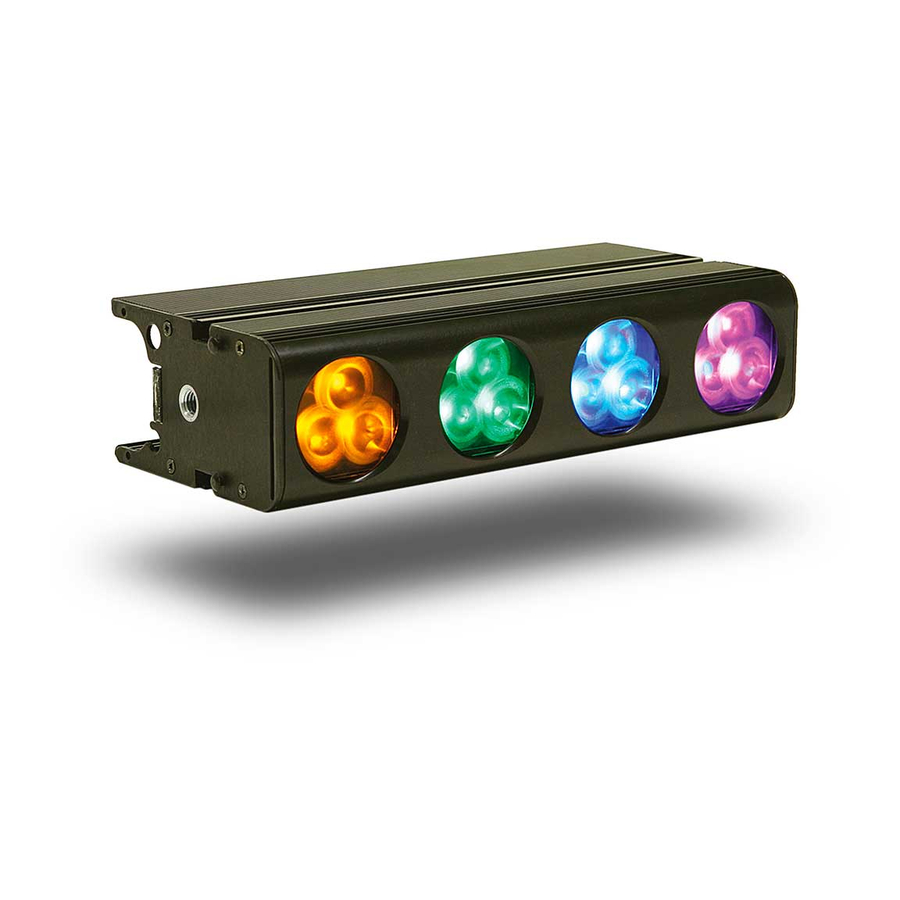
Product overview 1.1 Chroma-Q Color Block 2 Following the enormous success of the Chroma-Q Color Block™ LED fixture with rental companies and end users alike, the manufacturer has combined the product's core elements of modularity and versatility with new single color RGBA optics, 530 lumens output (almost double the original model) and theatrical grade dimming to create the exceptional feature set of the Color Block 2 fixture. -
Page 5: Operation
Color Block PSU-05B The Color Block PSU-05B is a power supply suitable for up to 5 Color Block DB4 LED fixtures or 5 Color Block 2 LED fixtures. It can be controlled remotely via ANSI E1.11 DMX 512-A in a variety of modes to accommodate most applications or can operate independently as a stand alone system. - Page 6 Power and control data outputs from the Color Block power supply to the fixture is through an XLR 4-pin cable. The drain wire should be connected to the chassis of the XLR. Pin # Function Minimum Cable size Ground (-ve) 2.50mm²...
- Page 7 Color Block 2 User Manual V1.0 April 2009...
-
Page 8: Fixings
2.3 Fixings One of the strengths of the Color Block 2 fixture is its flexible fixing possibilities. The Color Block 2 fixture is supplied with an integral M10 clinch nuts at each end. These can be used to attach the Color Block 2 fixture to a standard hook clamp or the wide range of Color Block accessories listed below. - Page 9 The Color Block 2 fixture is supplied with an integral M10 clinch nuts at each end. These can be used to attach the Color Block 2 fixture to a standard hook clamp. Note: damage may occur if the bolt is too long. (M10x16 maximum) b.
-
Page 10: Control
Keyhole slots are provided to for vertical or horizontal fixing. 2.4 Control The Chroma-Q Color Block 2 is controlled via two models of addressable ANSI E1.11 USITT DMX512-A power supply units, the 5 way Color Block PSU-05B and the 30 way Color Block PSU-30. - Page 11 If left unadjusted at a main menu position for 5 second the LCD screen will revert to the Home position. a. Control Options 3 channel HSI (Hue, Saturation and Intensity) gives 2 colour channels for hue and saturation and a separate intensity channel. A separate definable intensity channel is particularly useful when creating intensity chases or when the grand master is used.
- Page 12 PSU-05B PSU-30 Mode Group System: CB2 System: CB2 Variable 7FX + 20 x HSI 7FX + 120 x HSI Cell 20 x HSI 120 x HSI Cell 20 x RGB (with *Magic Amber) 120 x RGB (with *Magic Amber) Block 6FX + 5 x HSI 6FX + 30 x HSI Block...
- Page 13 To edit the channel numbers and levels of a selected Look: Scroll to Look Store and press Enter, scroll to desired Look and press Enter to access the memory data. Scroll the wheel to select the channel number. To edit the channel level, press Enter and use the scroll wheel to adjust the level (shown as 0-255).
- Page 14 Channel 2 Colour Speed Saturation group 1 Green group 1 0-255 Variable speed of colour scrolling. From static at 0 to maximum at 255. Channel 3 Colour Fan Intensity group 1 Blue group 1 0-255 Variable fan of colour between / within groups.
- Page 15 colour scrolling. Smoothest is at 0. Most coarse is at 250. Rate will vary with scrolling speed. 255 will override effects and switch to RGB. Channel 5 Intensity Effects Saturation group 2 Green group 2 0 Static 1-63 Fade on, fade off. Variable range, 63 the fastest 64-127 Fade on, snap off.
- Page 16 Variable range, 255 the fastest. Channel 6 Intensity Fan 0-255 Variable fan of intensity effect within group. All units at the same intensity at 0. Alternating units on and off at 255. Channel 7 Hue group 1 Channel 8 Saturation group 1 Channel 9 Intensity group 1 Total...
- Page 17 h. PSU-05B DMX Personality Mode 14-15 In modes 14-15 all fixtures in the output are a group (All) PSU-05B Mode 14 (4ch) Mode 15 (4ch) (v2.1) RGBA RGBI (with *Magic Amber) Channel 1 Red group 1 Red group 1 Channel 2 Green group 1 Green group 1 Channel 3...
- Page 18 speed. 255 will override effects and switch to RGB. Channel 6 Intensity Effects Intensity group 2 Blue group 2 0 Static 1-63 Fade on, fade off. Variable range, 63 the fastest 64-127 Fade on, snap off. Variable range, 127 the fastest 128-191 Snap on, fade off.
- Page 19 groups. All units at the same intensity at 0. Alternating units on and off at 255. Channel 7 Hue for group 1 Hue group 3 Red for group 3 Channel 8 Saturation for group 1 Saturation group 3 Green for group 3 Channel 9 Intensity for group 1 Intensity group 3...
- Page 20 Channel 2 Green for group 1 Green for group 1 Channel 3 Blue for group 1 Blue for group 1 Channel 4 Amber for group 1 Intensity for group 1 Channel 5 Red for group 2 Red for group 2 Channel 6 Green for group 2 Green for group 2...
-
Page 21: Troubleshooting
p. PSU-30 DMX Personality Mode 16 In mode 16 grouping is variable PSU-30 (v2.1) Mode 16 (1ch) Look Store Channel 1 Channel levels and the corresponding Look numbers: Channel Channel Channel Look Look Look Level (%) Level (%) Level (%) 33–35 69-71 1–2... -
Page 22: Technical Specifications - Color Block Power Supply Units
Control protocol: ANSI E1.1 DMX-512A Connector in/out: XLR4 Maximum cable run: 60m / 200’ Cooling system: 1 x fan Construction: Anodised aluminium extrusion Colour: Black LED cells: LED per cell: 12 RGBA Total LED: Optics: Specialised close focus lens Beam angle: 25º... -
Page 23: Photometric Performance
Cooling: 1 x rear mounted fans, 5 x rear mounted fans, front/rear ventilation required front/rear ventilation required Approvals: EN55103-1, EN55103-2, IEC60950 4.3 Photometric Performance Photometric data for colour white Photometric data for colour red 3’/1m 6’/2m 9’/3m 12’/4m 15’/5m 3’/1m 6’/2m 9’/3m 12’/4m... - Page 24 Color Block 2 User Manual V1.0 April 2009...
- Page 25 Color Block 2 User Manual V1.0 April 2009...
- Page 26 Color Block 2 User Manual V1.0 April 2009...
-
Page 27: Maintenance
Maintenance With care, the Color Block 2 fixture and power supply units will require little maintenance. However, as the unit is likely to be used in a stage environment we recommend periodical internal inspection and cleaning of any resulting dust and cracked oil residue. Do not spray liquids on the front or rear panel. -
Page 28: Accessories
the cables are not coupled or uncoupled whilst the PSU is powered and that the PSU is correctly grounded. SYNC - RJ45 Used to synchronise the FX running on multiple PSU-05Bs. A straight wired RJ45 patch cable is suitable to connect units (not a crossover cable). Note: The SYNC connector on the PSU-05B is not using Ethernet.
Need help?
Do you have a question about the Chroma-Q Color Block 2 and is the answer not in the manual?
Questions and answers