Table of Contents
Advertisement
Advertisement
Table of Contents

Related Manuals for CareFusion Infant Flow LP SiPAP


Summary of Contents for CareFusion Infant Flow LP SiPAP
- Page 1 Infant Flow LP SiPAP and SiPAP Model M675 ® Service manual...
- Page 2 License Agreement. © 2008 – 2011 CareFusion Corporation or one of its subsidiaries. All rights reserved Infant Flow is a registered trademark of CareFusion Corporation or one of its subsidiaries. All other trademarks are property of their respective owners.
- Page 3 Service Manual Revision History Date Revision Changes September 2003 675-120(1) Release November 2004 Release manual in VIASYS Healthcare template using VIASYS Healthcare Respiratory Care nomenclature. December 2004 Revised per EO 27980. Removed the picture from the title page. Deleted the ESD warning from page 19. Removed “O2 Sensor”...
- Page 4 ® Infant Flow LP SiPAP Model M675 Date Revision Changes April 2010 Changed Ti to T throughout -High Figure 5 - Diagnostic screen updated Spelling correction from “GRD” to “GND” Added “Note: transducer must be attached.” Changed “10 V” to “11.10 V” Updated Table 6 - Error Codes (E50 - E54) and added Removed “Blender (Check Valves and Filter) Annually”...
-
Page 5: Warranty
One (1) year from date of shipment. The liability of CareFusion, (referred to as the Company) under this warranty is limited to replacing, repairing or issuing credit, at the discretion of the Company, for parts that become defective or fail to meet published specifications during the warranty period;... -
Page 6: Table Of Contents
® Infant Flow LP SiPAP Model M675 Contents Revision History ................iii Warranty .................... v Limitation of Liabilities ................ v Notices .................... viii EMC Notice ....................... viii MRI Notice ......................... viii Intended Use Notice ....................ix Regulatory Notice ....................... ix Classification ...................... - Page 7 Service Manual Chapter 6 – Operational Setup ................25 Preparing and Connecting the Equipment ........25 Switching On the IFSD ..............29 User Verification Test ..............30 Power-on Check ......................30 Two Point O Sensor Calibration ................31 Leak Test ........................32 Alarms Test ........................
-
Page 8: Notices
viii ® Infant Flow LP SiPAP Model M675 Notices EMC Notice This equipment radiates and is susceptible to radio frequency energy. If not installed and used in accordance with the instructions in this manual, electromagnetic interference may result. The equipment has been tested and found to comply with the limits set forth in BS EN60601-1-2 for Medical Electrical Equipment Part 1-2: General requirements for safety-collateral standard. -
Page 9: Intended Use Notice
Service Manual Intended Use Notice ® The Infant Flow LP SiPAP system, consisting of a Driver and Generator plus NCPAP Prongs and Masks, is a medical device intended for the provision of Bi-Level CPAP to produce a sigh. This system is for use in Hospital, Hospital Type facilities and intra-Hospital transport environments and is indicated for the treatment of Newborn and Infant patients. -
Page 10: Declaration Of Conformity Notice
EU Notified Body: BSI (Reg. No. 0086) Device Classification: IIb EU Notified Body: BSI (Reg. No. 0086) Trade names: Infant Flow LP SiPAP Manufactured by: CareFusion 22745 Savi Ranch Parkway Yorba Linda, CA 92887, USA If you have a question regarding the Declaration of Conformity for this product, please contact CareFusion. -
Page 11: Chapter 1 - Product Description
LP SiPAP and SiPAP systems is irrespective of patient demand or expiratory flows. This system has been designed and tested to perform optimally when used only with accessories available from CareFusion. These accessories include circuits and generators, prong and mask patient interfaces and bonnets. - Page 12 LP SiPAP and SiPAP systems have been designed and tested ® as complete systems using Infant Flow accessories. Only accessories approved for use should be used. If in doubt, please contact your local CareFusion representative. WARNING! ® The Infant Flow LP SiPAP system is compatible only with the Infant Flow LP Generator.
-
Page 13: Chapter 2 - Product Specifications
Service Manual Chapter 2 – Product Specifications Modes • NCPAP • NCPAP with breath rate monitoring and low rate alarm • BiPhasic (time triggered) • BiPhasic (time triggered) with breath rate monitoring and low rate alarm • BiPhasic tr (patient triggered ) with breath rate monitoring, low breath rate alarm, and apnea back up Controls •... -
Page 14: Alarms
® Infant Flow LP SiPAP Model M675 Alarms • High airway pressure – 3 cmH20 above measured airway pressure • High circuit pressure – maximum 11 cmH20 in time triggered Biphasic mode • High circuit pressure – maximum 15 cmH20 in patient triggered Biphasic tr mode (Comprehensive only. -
Page 15: Atmospheric & Environmental
Service Manual Atmospheric & Environmental • Temperature Range-Operating: 5 – 40° C • Storage: 0 - 50° C • Relative Humidity -Operating: 0 – 90% non-condensing • Storage: 0 – 90% non-condensing Physical • Dimensions (driver only)-(W x H x D) 26 x38 x 23.5 cm / 10.25 x15 x 9.25 in •... - Page 16 ® Infant Flow LP SiPAP Model M675 ® Infant Flow LP SiPAP and SiPAP Model M675 675-120 Rev. G...
-
Page 17: Chapter 3 - Warnings And Cautions
• The Infant Flow LP SiPAP system is compatible only with the Infant Flow LP Generator. The prescribed nCPAP level will not be obtained if other variable flow generators are used. - Page 18 ® Infant Flow LP SiPAP Model M675 • ® Do not use conductive patient circuits with the Infant Flow LP SiPAP Driver. • Nasal CPAP can cause nasal irritation, septal distortion, skin irritation and pressure necrosis. Observe the usage guidelines to minimize these complications.
-
Page 19: Cautions
Infant Flow SiPAP accessories. Only accessories approved for use should be used. If in doubt, please contact your local CareFusion representative. • Where the integrity of the external protective earth conductor is in doubt, the equipment shall be powered by its internal power source (battery). - Page 20 ® Infant Flow LP SiPAP Model M675 ® Infant Flow LP SiPAP and SiPAP Model M675 675-120 Rev. G...
-
Page 21: Chapter 4 - System Construction
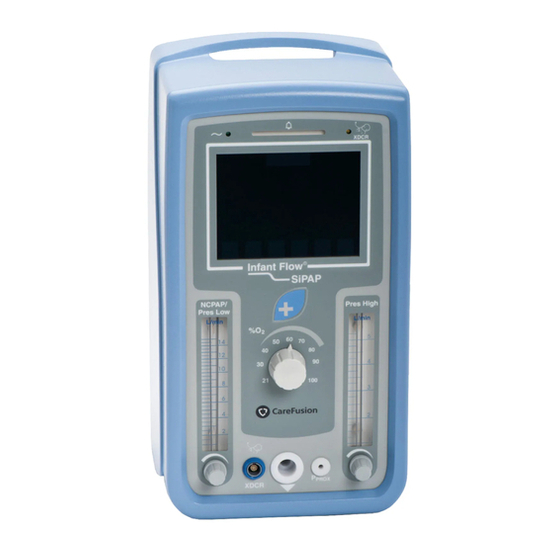
Service Manual Chapter 4 – System Construction CAUTION! Where the integrity of the external protective earth conductor is in doubt the equipment shall be powered by its internal power source (battery). The IFSD is AC powered with an integral rechargeable DC battery that provides power for up to two hours without any interruption of performance or function. - Page 22 ® Infant Flow LP SiPAP Model M675 Figure 1: IFSD Front Panel Gas Module The function of the gas module is to take air and oxygen, blend them into the required mixture and deliver this mixture to the patient at the prescribed flow rate. The gas module also measures the oxygen concentration, measures the patient pressure, provides an auxiliary gas outlet (optional) and provides switched Biphasic flow.
- Page 23 Service Manual Electronics Module The function of the electronics module is to power the unit either by AC mains supply or DC emergency battery supply, to control the gas module and read the gas module sensors. The main components are a power supply unit, a rechargeable battery, a main processor PCB, LED PCB, Valve/Sensor PCB and a LCD screen (touch screen).
- Page 24 ® Infant Flow LP SiPAP Model M675 Figure 3: IFSD Internal Components 675-120 Rev. G...
-
Page 25: Touch Screen
Service Manual Front Panel Module The function of the front panel module is to house the gas and electrical connections to the patient, Operator controls and indicators. The module consists of a front panel plate, the touch screen with key pad, flowmeters and FiO control, patient connectors and indicators and an ambient light sensor. - Page 26 ® Infant Flow LP SiPAP Model M675 condition resets itself, the yellow alarm bar remains to alert the clinician of a previous problem. Caution/Information The Caution/Information icon alerts the Operator to read this manual. It flashes during an alarm condition. Mode Indicator The Mode Indicator shows four question marks when in Start up or Adjust and changes to show the applicable mode in use (e.g.
-
Page 27: Alarm Conditions
Service Manual Alarm Conditions Audible and visible alarm indications are given to alert the Operator to specified conditions that affect the operation of the unit. The electronic alarm limits are automatically set after two minutes without Operator inputs but the Operator can manually set the alarm parameters for certain conditions if required. - Page 28 ® Infant Flow LP SiPAP Model M675 Table 2 - Diagnostics Screen Boxes Description DIPS The DIPS box shows the position of the DIP switches on the main processor PCB. Position 1 is on and 0 is off. CONTRAST The contrast indicator box is for use in the factory for setting the screen INDICATOR contrast.
-
Page 29: Chapter 5 - Theory Of Operation
Service Manual Chapter 5 – Theory of Operation Gas Flow With the oxygen and air connections connected and the power switched on, oxygen and air at 386 kPa (56 psig) flows to the blender. The air passes through a water trap with an integral filter where any moisture in the air is removed. - Page 30 ® Infant Flow LP SiPAP Model M675 Figure 6: IFSD Gas Flow Schematic 675-120 Rev. G...
- Page 31 Service Manual The patient pressure is shown on the touch screen and is monitored by a pressure sensor which sends the signal to the main processor. A zeroing valve automatically checks the pressure readings against atmospheric pressure to ensure accuracy of the patient pressure readings.
-
Page 32: Electronic Functions
® Infant Flow LP SiPAP Model M675 Electronic Functions Sensors mounted on the valve/sensor PCB monitor pressure, flow rate and oxygen. Sense signals for each of the valves allow the micro-controller to monitor the valve’s state and determine whether the valve is connected or short circuited. Current to the valve sensor PCB is limited via the fuses below a 10 VA limit to ensure safety in a possible oxygen enriched environment. -
Page 33: Electrical Layout
Service Manual Electrical Layout Figure 8 shows the electrical wiring and PCB connector layout. Figure 8: IFSD Electrical Wiring Diagram 675-120 Rev. G... -
Page 34: Fault Management
® Infant Flow LP SiPAP Model M675 Fault Management When a software detectable fault condition occurs, the unit still allows a basic level of treatment to the patient. Table 4 shows the fault conditions and the level of control available. Table 4 - Faults, Available Modes and Control Functions Measurements Software Control Modes... -
Page 35: Chapter 6 - Operational Setup
If desired, connect the transducer module to the sensor and to the IFSD. WARNING! The Infant Flow LP SiPAP system is compatible only with the Infant Flow LP Generator. The prescribed nCPAP level will not be obtained if other variable generators are used. - Page 36 ® Infant Flow LP SiPAP Model M675 ® Infant Flow SiPAP Driver or SiPAP Driver ® Infant Flow LP Generator or Generator Figure 9: Patient Connections WARNING! Check that the water trap is empty before use and empty it frequently during use.
- Page 37 Service Manual Make sure that the water trap is empty. If necessary, empty any water from the trap (refer to Chapter 3, Maintenance). Gas Flow Pressure Setting The IFSD provides a virtually constant airway pressure irrespective of patient demand or expiratory flows via the specially designed generator and nasal prongs. This is the reason for the IFSD’s ability to provide superior NCPAP.
- Page 38 ® Infant Flow LP SiPAP Model M675 Flow Pressure Nomogram (for reference only) to show typical flow pressure relationships. This is not meant to establish actual product performance. Figure 11 – Flow Pressure Nomogram for LP SiPAP Individual devices have a tolerance of up to ±15 percent from that illustrated in the nomogram and, in particular, at pressures below 2cmH 675-120 Rev.
-
Page 39: Switching On The Ifsd
Service Manual Switching On the IFSD WARNING! Do not attach the Generator to the patient until the initial set up is complete. Put the power switch on the back panel to the position. • the warning bar comes on • the green power light remains on •... -
Page 40: User Verification Test
® Infant Flow LP SiPAP Model M675 User Verification Test WARNING! ® ® Do not attach the Infant Flow LP Generator or the Infant Flow Generator to the patient until User Verification and initial setup into NCPAP mode is complete. CAUTION! Although failure of any of the above tests will not prevent the ventilator from functioning, it should be checked to make sure it is operating correctly before use... -
Page 41: Two Point O Sensor Calibration
Service Manual Two Point O Sensor Calibration Enter the Calibration Screen from the Setup Screen by pressing the calibration button on the lower right hand corner of the touch screen. Ensure there is a minimum 8 LPM set on the NCPAP/PRES Low Flowmeter. In addition, ensure there is a minimum of 3 LPM set on the NCPAP/High Flowmeter. -
Page 42: Leak Test
® Infant Flow LP SiPAP Model M675 Leak Test Have the patient circuit and generator assembled as shown in Figure 3. Connect the patient interface (prong or mask) to the generator (see Chapter 5, Step by Step Fixation) and occlude the opening to the patient. If not powered up already, switch on the power to the driver. -
Page 43: Alarms Test
Service Manual Alarms Test WARNING! Prior to patient application, ensure that all User Verification testing and calibration procedures are successfully completed. User Verification testing and calibration procedures must be done off patient. Note: Following each alarm verification test, ensure that control settings and alarm limits are reset as instructed before proceeding to the next test. - Page 44 ® Infant Flow LP SiPAP Model M675 Low % O Alarm: Adjust the % O control to 25%. Verify that the Low %O alarm activates. Return the O control setting to 30%. Reset alarms by pressing the Alarm Mute / Reset button for 3 seconds. Loss AC Alarm: Disconnect the AC power cord from the wall outlet.
-
Page 45: Infant Flow Lp Sipap/Sipap User Verification Test Checklist
Service Manual ® Infant Flow LP SiPAP/SiPAP User Verification Test Checklist Driver Serial Number:_____________________ Test Date:_________________ TEST PASS FAIL Automated Tests Power On Check Manual Tests Two Point O Sensor Calibration Patient Circuit Leak test Manual Alarms Checks Low Airway Pressure Alarm High Airway Pressure Alarm High O Alarm... -
Page 46: Setting Up The Equipment
® Infant Flow LP SiPAP Model M675 Setting up the Equipment The procedures show the screen set up for all modes. If a mode is not applicable to the model in use, go to the next applicable step. Adjust the NCPAP Pres Low Flowmeter to indicate the required flow rate. When done, touch the flashing button to confirm the initial setting The button icon changes to a... -
Page 47: Setting The Ncpap Parameters
Service Manual When the alarm limits have been set, the screen changes to the Mode Selection Screen and defaults to the nCPAP mode. • The alarm limits are set. Touch NCPAP, NCPAP+Apnea, BiPhasic, BiPhasic+Apnea, or BiPhasic Tr to enter the Parameter Set up Screen for each mode. Note: When the Mode Selection screen is showing, NCPAP treatment will always be delivered. -
Page 48: Setting The Biphasic Parameters
® Infant Flow LP SiPAP Model M675 Note: If a high priority alarm occurs, the key pad automatically unlocks. To return to the Mode Selection Screen, touch the button. Setting the BiPhasic Parameters For BiPhasic+Apnea function the transducer interface and the abdominal respiratory sensor must be connected. -
Page 49: Setting The Triggered Biphasic Parameters
Service Manual Note: The I/E rate changes accordingly. To return to the Mode Selection Screen, touch the button. Note: The button is shown with a pink background if an alarm condition occurs. If this occurs, the button cannot be operated until the alarm condition has been cleared or silenced using the alarm button. - Page 50 ® Infant Flow LP SiPAP Model M675 To adjust the parameters, touch the button. The screen changes to the BIPHASIC TR Adjust Screen. Parameters T , Rb and Tapnea can now be adjusted. -High To return to the Mode Selection Screen, touch the button.
-
Page 51: Calibration
Service Manual Calibration WARNING! Calibration must only be done when the unit is not connected to the patient. From the Start Up Screen touch the button. The screen changes to the Calibration Screen. • The alarm limits are disabled. Turn the FiO control to 21 and confirm by touching the flashing button. -
Page 52: Fault Indications
® Infant Flow LP SiPAP Model M675 Fault Indications Refer to Table 1 (all models) and Table 2 (BiPhasic and BiPhasic Tr models only) for the fault indications for specific faults and the procedures for resetting or canceling. Discharged Battery When the battery voltage is too low to power the circuits, the screen changes to the Power Down Screen. - Page 53 Service Manual Table 5 - Faults and Indications Indications and Method of Resetting Alarm Method of Setting Actions or Canceling Minimum oxygen Always active when Intermittent high level Restore FiO level to concentration power is on. Audible Alarm. above the low limit (<...
- Page 54 ® Infant Flow LP SiPAP Model M675 Indications and Method of Resetting Alarm Method of Setting Actions or Canceling Low oxygen concentration Set automatically on Intermittent high level Push the Alarm (< 5 FiO below set point entering NCPAP Audible Alarm. Button once to stop at time alarm is set for 15 mode for the first time...
- Page 55 Service Manual Indications and Method of Resetting Alarm Method of Setting Actions or Canceling Over pressure (Patient Always active when Intermittent high level Reduce pressure to pressure power is on. Audible Alarm. below the high O when in > 11 cmH pressure limit then Warning Bar flashes.
- Page 56 ® Infant Flow LP SiPAP Model M675 Indications and Method of Resetting Alarm Method of Setting Actions or Canceling Battery fault Automatic Intermittent high level Cannot be reset. (Battery disconnected or Audible Alarm. Push the Alarm failing to take or hold Button once to stop Warning Bar flashes charge).
- Page 57 Service Manual Indications and Method of Resetting Alarm Method of Setting Actions or Canceling Flowmeter fault. Flowmeter fault No flow indications or Refer to Service flow cannot be Engineer. adjusted. Electrical fault. Electrical fault External power light Refer to Service does not match screen Engineer.
-
Page 58: Diagnostics
® Infant Flow LP SiPAP Model M675 Diagnostics Diagnostic mode is accessed by enabling DIP switch 6 and exited by disabling it. Enable DIP switch 6 during Start Up, Adjust or Mode Selection. The screen changes to the Diagnostics Menu Screen (for a description of the displayed information, refer to pages 17-18): •... - Page 59 LCD driver (no external power). Non-volatile memory fault. Unusable - unable to User lockout Call retrieve/set unit ‘Error number’ CareFusion configuration and prompt. technical calibration data. support for assistance. 675-120 Rev. G...
- Page 60 No backup – battery will Battery low alarm low (<14 V) to charge not charge. continues even Contact battery (battery flat). when external CareFusion power applied. technical ‘Error number’ support. alarm prompt. Analog supply rails out of Unusable - unreliable...
- Page 61 Unusable – valve User lockout Power cycle watchdog disabled. disabled. ‘Error number’ unit. If fault prompt. still occurs, Contact CareFusion technical support. Pressure sensor fault Unusable – pressure User lockout Replace the (ADC hits rail). sensor readings invalid. ‘Error number’...
- Page 62 ® Infant Flow LP SiPAP Model M675 Error Software Corrective Fault Condition Consequence Response Action Code Oxygen sensor fault (ADC No oxygen monitor – ”E50” displayed; Replace the hits rail). oxygen sensor high priority O2 Sensor readings invalid. alarm. and re- calibrate O sensors Oxygen sensor cannot be...
- Page 63 No breath signal from PT Untriggerable - Patient Reduced Contact module although CAN may be in Apnea but functionality CareFusion data does not report PT module may be ‘Error number’ technical Apnea. dysfunctional. alarm prompt. support No trigger signal from PT Untriggerable –...
- Page 64 LP SiPAP Model M675 Error Software Corrective Fault Condition Consequence Response Action Code Unknown error detected. Unusable – software User lockout Contact unreliable. ‘Error number’ CareFusion prompt. technical support * - Generated as a consequence of the fault. 675-120 Rev. G...
-
Page 65: Chapter 7 - Maintenance
Service Manual Chapter 7 – Maintenance Maintenance Frequencies There are three different types of Preventative Maintenances required for the LP SiPAP/SiPAP system. 1. Annual PM- Placement of annual PM Kit, P/N 777242-101 in unit. Contents include: battery, O2 sensor, various filters and O-rings. 2. -
Page 66: Cleaning
Dispose of scrap units in accordance with the local regulations Removal and Fitting of Parts – General Only parts approved by CareFusion may be used in this unit. Remove all attached patient connections before removal of parts. Disconnect the unit from the power supply. - Page 67 Service Manual Table 7 shows the part numbers, components and page reference for removal directions for the annual pm kit. Table 7- Annual PM Kit Components Part Number Components Removal Directions Page Number 777244 Battery 06804 Oxygen Filter 465474 Banjo Screw O-Ring 672-024-SA Fuel Cell Filter/Restrictor and O-rings...
- Page 68 ® Infant Flow LP SiPAP Model M675 Table 8 shows the two year pm components and page number references. Table 8- Two Year PM Components Part Number Component Removal Direction Page Number 11329 or 11798 Blender 64 – 67 10003 Low Flow MicroBlender L1130 Low Flow MicroBlender Overhaul Kit...
-
Page 69: Removal And Fitting Of Case
Service Manual Removal and Fitting of Case Refer to Figure 12. Removal Remove eight screws (1) on the rear panel and two screws (1) on the case- bottom. Pull off the case (2). Fitting Install the case (2) over the main frame, making sure that all wires and tubing are secure and cannot be trapped by the case. -
Page 70: Removal And Fitting Of Battery
® Infant Flow LP SiPAP Model M675 Removal and Fitting of Battery Refer to Figure 13. Removal Remove the case. Disconnect the battery lead connector SK3 (1) (cable 5) from the plug PL3 on the Main Processor PCB. Remove the screw (2) on the rear panel and remove the spacer (3). -
Page 71: Removal And Fitting Of Oxygen Filter
Service Manual Figure 13: Battery Removal/Fitting Removal and Fitting of Oxygen Filter Note: This procedure can be done without removing the case. Refer to Figure 14. Removal Remove the banjo screw (1) on the end of the air/oxygen mounting block (2). Remove the filter (3). -
Page 72: Removal And Fitting Of Fuel Cell Filter/Restrictor
® Infant Flow LP SiPAP Model M675 Removal and Fitting of Fuel Cell Filter/Restrictor Refer to Figure 15. Removal Remove the case. Remove the oxygen filter screw (1) from the flow mixer block (2). Remove the filter/restrictor (3). Remove and discard the O-ring (4) and the O-ring (5) from the oxygen filter screw (1). -
Page 73: Removal And Fitting Of The Oxygen Sensor
Service Manual Removal and Fitting of the Oxygen Sensor Refer to Figure 16. Removal Remove the case. Disconnect the connector SK12 (1) from the top of the oxygen sensor. If necessary, remove the screw (2) securing the C clip (3) and release the C clip securing the cable (cable 7) and the ferrite. -
Page 74: Removal And Fitting Of Blender And Components
Removal and Fitting of Blender and Components Refer to Figure 17. Note: Two different blenders are used in the LP SiPAP, P/N 11329 and 11798. These blenders are NOT interchangeable. Contact CareFusion technical support for further assistance. Removal Remove the case. - Page 75 This will be located either on the back of the unit to the right of the inlet block or on the inlet gas block itself. Refer to directions in the blender service manual to replace the reed alarm. Note: If the alarm cap is not in either location, contact CareFusion technical support. 675-120 Rev. G...
- Page 76 ® Infant Flow LP SiPAP Model M675 Figure 17: Blender and Components Removal/Fitting 675-120 Rev. G...
- Page 77 Service Manual Fitting Fit the blender or refurbished blender (22) with the four screws (21) into the front frame panel. Connect the air supply (17), the oxygen supply (18), the whistle outlet tube (19) and the main outlet (20). Note: See Appendix D for the tubing diagram.
-
Page 78: Removal And Fitting Of Water Trap Filter
® Infant Flow LP SiPAP Model M675 Removal and Fitting of Water Trap Filter Refer to Figure 18. Removal Remove the filter bowl (1) using the water trap tool (P/N 673-051-A) included with the IFSD. Pull out and discard the filter (2) from the water trap. Fitting Install the new filter (P/N 467269) (2) in the water trap. -
Page 79: Removal And Fitting Of Case Bleed Filtered Restrictor
Service Manual Removal and Fitting of Case Bleed Filtered Restrictor Refer to Figure 18. Removal Remove the case and loosen the clamp securing the restrictor to sheet metal. Note restrictor flow direction, then remove the case bleed filtered restrictor (3) from the 4mm tube. -
Page 80: Removal And Fitting Of Valve/Sensor Pcb
® Infant Flow LP SiPAP Model M675 Removal and Fitting of Valve/Sensor PCB See Figure 17. Removal Remove the case. Disconnect the fuel cell connector SK1 (14) at PL1 on the Valve/sensor PCB. Disconnect the dump/vent/valve connector SK3 (15) at PL3 on the Valve/Sensor PCB. -
Page 81: Chapter 8 - Explanation Of Symbols
Indicates ATTENTION, consult ACCOMPANYING Symbol #03-02 IEC 60878 DOCUMENTS Symbol #5016 IEC 60417 This symbol indicates a FUSE. This symbol indicates an INTERNAL BATTERY CareFusion Symbol FUSE 2.5A/T 250 V Fuse holder and fuse rating 101010 Electrical AC inlet Symbol #5032 IEC 60417 The equipment is suitable for alternating current. - Page 82 LP SiPAP Model M675 Symbol Source / Compliance Meaning Operating temperature range of unit Warning Bell CareFusion Symbol CareFusion Symbol Respiratory Connection and Indicator This symbol indicates TYPE B equipment, which indicates equipment that provides a particular Symbol # 5333 IEC 60417...
- Page 83 Service Manual Symbols used on buttons: The following symbols are used to label user input areas within the graphical display. As needed displays in this table are shown separately as Domestic US configuration displays (left-hand column) and International configuration displays (right-hand column).
- Page 84 ® Infant Flow LP SiPAP Model M675 Nasal CPAP mode with breath rate monitoring BiPhasic mode BiPhasic mode with breath rate monitoring BiPhasic Tr mode with breath rate monitoring Manual Breath. Single breath cycle at current settings for T , NCPAP Pres high and O %.
-
Page 85: Appendix A - Oxygen Leak Test
Service Manual Appendix A – Oxygen Leak Test Oxygen Leak Test This test should be performed after and Preventative Maintenance and/or repair has been done on the LP SiPAP. This test will check for leaks within the enclosure. Test equipment needed: Calibrated oxygen analyzer 1. - Page 86 ® Infant Flow LP SiPAP Model M675 7. Set the pressure High Flowmeter to about 2 LPM then push its soft key button under the right Flowmeter icon. The Respiratory Sensor option is not required, but to finish, select this soft key button.
- Page 87 Service Manual 10. Accept the default BiPhasic settings by selecting the BiPhasic soft key again (Figure A–4). Figure A–4 11. Verify that the measured value on the external oxygen analyzer doesn’t exceed 23% FiO . If so, then troubleshoot for an oxygen leak. Check all the fittings and connections and repeat the Oxygen Leak Test (Figure A–5).
- Page 88 ® Infant Flow LP SiPAP Model M675 ® Infant Flow LP SiPAP and SiPAP Model M675 675-120 Rev. G...
-
Page 89: Appendix B - Product Configurations
Service Manual Appendix B – Product Configurations Non-US Configuration Parameters Parameter Accuracy Units ±3 Set Oxygen concentration, %O ±15% CPAP flow rate ± 15% Bi-level additional flow rate ± 0.005 BiPhasic on time, T (inspiration time) 3.0 * seconds -High ±... - Page 90 ® Infant Flow LP SiPAP Model M675 ® Infant Flow LP SiPAP and SiPAP Model M675 675-120 Rev. G...
-
Page 91: Appendix C - Spare Parts
Service Manual Appendix C – Spare Parts Part Number Description 467472 BLENDER CONTROL KNOB (for blender part number 11329) 467468 CAP, BLENDER CONTROL KNOB 467471 POINTER, BLENDER CONTROL KNOB 467469 FLOWMETER KNOB 467470 CAP, FLOWMETER KNOB 675-308 CASE 467467 FOOT, POLYURETHANE .5OD 467466 WASHER M3 CRINKLE BECU (FOR CASE) 675-200... - Page 92 ® Infant Flow LP SiPAP Model M675 Part Number Description 467455 SWITCH COVER 22562 BLENDER KNOB (for blender part number 11798) 675-256 SWITCH CABLE ASSY 675-310-EN FRONT PANEL (English) 675-310-FR FRONT PANEL (French) 675-310-RO FRONT PANEL (Icon) 675-312 CONNECTOR PATIENT INLET 675-316 MK3 TRIGGER LEUR 675-209...
-
Page 93: Appendix D - Pneumatics Assembly
Service Manual Appendix D – Pneumatics Assembly 675-120 Rev. G... - Page 94 ® Infant Flow LP SiPAP Model M675 675-120 Rev. G...
-
Page 95: Glossary
Service Manual Glossary Term Meaning Temporary inability to breathe; monitoring of breathing (non-US Apnea labeling) Breaths per minute (applies to each of spontaneous, triggered and mandatory) Centimeters of Water (Pressure) CPAP Continuous Positive Airway Pressure Fraction of Inspired Oxygen Patient attachment for delivering CPAP, used with nasal prongs or Generator mask Inspiration/Expiration ratio... - Page 96 ® Infant Flow LP SiPAP Model M675 Term Meaning Apnea Interval (non-US labeling) or Low Breath Rate (LBR) monitor alarm time (US-labeling); both in seconds apnea This mnemonic may also be associated with an alarm icon Machine breath inspiration time (seconds) -High Application of NCPAP, BiPhasic, BiPhasic Tr, with or without Treatment...
Need help?
Do you have a question about the Infant Flow LP SiPAP and is the answer not in the manual?
Questions and answers