Table of Contents
Advertisement
C
o
l
o
r
t
r
a
c
i
s
t
h
e
T
r
a
d
i
n
g
N
C
o
l
o
r
t
r
a
c
i
s
t
h
e
T
r
a
d
i
n
g
N
C
o
l
o
r
t
r
a
c
L
t
d
R
e
g
i
s
C
o
l
o
r
t
r
a
c
L
t
d
R
e
g
i
s
a
m
e
o
f
C
o
l
o
r
t
r
a
c
L
t
d
a
n
d
a
m
e
o
f
C
o
l
o
r
t
r
a
c
L
t
d
a
n
d
t
e
r
e
d
n
o
.
2
4
4
3
0
8
7
i
n
E
n
g
l
a
n
d
.
t
e
r
e
d
n
o
.
2
4
4
3
0
8
7
i
n
E
n
g
l
a
n
d
.
C
o
l
o
r
t
r
a
c
I
n
c
,
i
n
c
o
r
p
o
r
a
C
o
l
o
r
t
r
a
c
I
n
c
,
i
n
c
o
r
p
o
r
a
R
e
g
i
s
t
e
r
e
d
O
f
f
i
c
e
:
1
1
5
c
M
i
l
t
o
n
R
e
g
i
s
t
e
r
e
d
O
f
f
i
c
e
:
1
1
5
c
M
i
l
t
o
n
t
i
n
g
T
a
n
g
e
n
t
a
n
d
A
N
A
t
e
c
t
i
n
g
T
a
n
g
e
n
t
a
n
d
A
N
A
t
e
c
R
o
a
d
,
C
a
m
b
r
i
d
g
e
,
U
K
R
o
a
d
,
C
a
m
b
r
i
d
g
e
,
U
K
h
.
h
.
Advertisement
Table of Contents

Related Manuals for Colortrac SmartLF Cx40m


Summary of Contents for Colortrac SmartLF Cx40m
- Page 2 Fax: +44 (0)1480 464620 www.colortrac.com Colortrac Ltd makes no warranty with respect to this document and disclaims any implied warranties of merchantability or fitness for a particular purpose. Information in this document is subject to change without notice. Colortrac Ltd assumes no responsibility for errors that may appear in this document.
-
Page 3: Table Of Contents
Cx40 Service Manual NOTES: Contents Chapter Description Page Introduction Models Covered By This Manual Tools Required How To Contact Technical Support Safety Safety Warnings EMC Testing Removing & Replacing Panels From Scanner Removing The Left Hand Cover Removing The Right Hand Cover Opening Access Panel Removing Top Lid Cover Removing Paper Guide Assembly... -
Page 4: Introduction
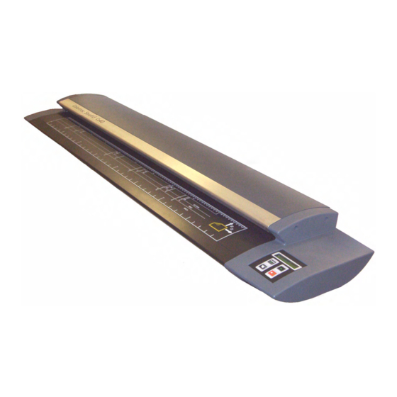
Models covered by this manual This manual contains information to assist in the repair and maintenance of the SmartLF scanners from Colortrac. It acts as a reference to service engineers who are approved by Colortrac. There are 3 models: SmartLF Cx40m Monochrome Scan width of 40”... -
Page 5: Tools Required
CD’s are ONLY available for approved engineers and will NOT be issued to end-users How to contact Technical Support Although Colortrac technical support group will do their best to help any service engineer in difficulties in the field, we accept no responsibility if a non-approved distributor/engineer damages any part of the scanner during a field visit. -
Page 6: Safety
4.2 EMC Testing All Colortrac scanners, which includes the model, have under gone and conform to EMC and FCC .The EMC test is carried out to assure that no signals that could cause interference are emitted from the scanner or that no external signal will interfere with the scanner. -
Page 7: Removing & Replacing Panels From Scanner
Cx40 Service Manual Removing and Replacing Panels from the Scanner. NOTES: Removing The Left Hand End Cover. To remove the Left Hand end cover, that covers the control panel of the scanner: Remove the 5 x M5 Pan Head Screws holding end cover to the scanner. -
Page 8: Removing The Right Hand Cover
Cx40 Service Manual Removing The Right Hand End Cover. NOTES: To remove the Right Hand end cover, that covers the control panel of the scanner: Remove the 5 x M5 Pan Head Screws holding the end cover to the scanner. Remove the end cover and keep it, with the 5 x screws, in a safe place ready for re-assembling. -
Page 9: Opening Access Panel
Cx40 Service Manual Opening Access Panel. NOTES: To open the rear access panel to be able to get to the Main Processor board and the PSU (power supply unit): Unplug mains lead and USB Connector. Remove the 8 x M3 Black Anodised Pan Head screws holding the rear panel in place. - Page 10 Cx40 Service Manual NOTES: Gently lower the panel down. The panel is hinged so will not need to be totally removed. Make sure that none of the cables are being pulled tight or have caught on anything while in the lowered position. Page 10 of 80...
-
Page 11: Removing Top Lid Cover
Cx40 Service Manual Removing Top Lid Cover. NOTES: To remove the top lid cover to gain access to the inside of the paper guide assembly: Remove the top cover to gain access to the pinch rollers and paper hold down rollers. Open paper guide assembly by releasing the 2 x latches at either end. - Page 12 Cx40 Service Manual NOTES: Prop the lid open with the safety lever. On the Left Hand side of scanner. Use a pozi-drive screw driver, remove the 2 x countersunk screws at either end on the paper guide assembly. Page 12 of 80...
- Page 13 Cx40 Service Manual NOTES: Completely remove the lid cover to reveal the inner cover plate. Release the safety lever and gently lower paper guide assembly. Page 13 of 80...
- Page 14 Cx40 Service Manual NOTES: Remove the 14 x pan head screws from the inner cover plate. Store the cover plates somewhere to avoid damage until needed from re-assembling. Re-assembly in reverse order. Page 14 of 80...
-
Page 15: Removing Paper Guide Assembly
Cx40 Service Manual Removing Paper Guide Assembly. NOTES: To completely remove paper guide assembly: Remove the Left Hand end cover as in chapter 5.1 page 7. Remove the Right Hand end cover as in chapter 5.2 page 8 Using a flat head screwdriver, loosen the hinge pins on either side of the paper guide assembly. -
Page 16: Replacing Paper Guide Assembly
Cx40 Service Manual NOTES: Lift the complete paper guide assembly out of the scanner, and store safely to prevent damage. Replace as described in chapter 5.5.1 page16 5.5.1 Replace the Paper Guide Assembly. Make sure the safety lever is moved across the front of the paper tray so that it is not in the way when placing paper guide assembly back in place. - Page 17 Cx40 Service Manual NOTES: Position the paper guide assembly back on to the scanner. Make sure the levers are at the front and the hinge is at the back. Make sure the front levers are on top of the locking pin before fixing the paper guide assembly into place.
- Page 18 Cx40 Service Manual NOTES: The holes in the paper guide assembly needs to be in-line with the threaded bush of the scanner end cast for the hinge pin to go through. Using a screwdriver through the hole, move the holes in line with each other.
- Page 19 Cx40 Service Manual NOTES: Tighten hinge pin using flat screwdriver. Replace the Left Hand end cover in the reverse order of chapter 5.1 Page 7. Replace the Right Hand end cover in the reverse order in chapter 5.2 Page 8. Page 19 of 80...
-
Page 20: Replacing Boards And Components
Cx40 Service Manual Replacing Boards and Components. NOTES: Replacing Control Panel or Display Board Remove the Right Hand end cover as shown in Chapter 5.2 page To remove display board, first disconnect the ribbon cable at the front of board. Remove the 4 x M3 nuts underneath the display board using the 5.5mm nut-spinner. - Page 21 Cx40 Service Manual NOTES: Before removing cables, use a pen/pencil to indicate which paper sensor cable is connected to which connector. Disconnect the ribbon cable to the Combined Main board and the paper sensor cables, then remove board. Page 21 of 80...
- Page 22 Cx40 Service Manual NOTES: If replacing the display board, remove the ‘Pic Chip’ at this point and place in the new board making sure it is fitted correctly in the socket. To remove the keypad, remove the 2 x M4 pan head screw to remove whole panel.
- Page 23 Cx40 Service Manual NOTES: Refit (or fit the new panel at this point) the keypad panel with the keypad attached by inserting the 2 x M5 pan head screws with the cable hanging in the front of scanner. Insert countersunk screws from top of the keypad, with the short screws (screw 1) in the front 2 holes and longer screws (screw 2) in the back 2 holes.
- Page 24 Cx40 Service Manual NOTES: Reconnect the ribbon cable from Combined Main Board and the cables from the paper sensors making sure the paper sensors are inserted in the correct way as marked during removal of the board (Fit new board at this point with the ‘pic chip’ inserted). Holding one of the 2 long spacers in position, insert display board onto the long countersunk screw in rear left hand corner, holding in place with 1 x M3 nut.
- Page 25 Cx40 Service Manual NOTES: Insert the front short spacers making sure that the sloped end is at the bottom and positioned so that is slopes towards the rear of board then insert M3 nuts and tighten all four nuts using the 5.5mm nut-spinner.
-
Page 26: Replacing Scan Glass Or Cis
Cx40 Service Manual NOTES: Replacing Scan Glass or CIS Open paper guide assembly by releasing the 2 x latches at either end. Prop the paper guide assembly with the safety lever on Left Hand side of the scanner. Using a thin Allen key / screwdriver, lift the first scan glass from it’s location in the CIS mounting bracket. - Page 27 Cx40 Service Manual NOTES: Lift the glass completely from the CIS mounting bracket, and store If the glass is being replaced, fit in a safe place to prevent damage. the new glass at this point, making sure the thickest black screening is towards the front of the scanner.
- Page 28 Cx40 Service Manual NOTES: Remove the 2 x screws at Right Hand end of CIS mounting bracket. Remove 2 x screw at Left Hand end of CIS plate. Page 28 of 80...
- Page 29 Cx40 Service Manual NOTES: Remove the 5 x screws that hold the CIS bracket down along the length. Gently lift the CIS mounting bracket out, being careful not to pull on the CIS cables that can be broken if pulled out of sockets incorrectly.
- Page 30 Cx40 Service Manual NOTES: Gently pull the ribbon cables out of each CIS in turn to free the mounting bracket from the scanner. These cables need to be handled carefully to prevent the cores from snapping or being damaged. It is recommended that this process can only be repeated maximum of 10 times, the cables need to be replaced if it exceeds that amount of times.
- Page 31 Cx40 Service Manual NOTES: Release the CIS by loosening the 2 x grub screws in the side wall of the mounting bracket. Use an Allen key / screwdriver to lift the CIS from its mounting location, making sure that no damage it caused to the CIS during this procedure.
- Page 32 Cx40 Service Manual NOTES: Lift the CIS out of it location, if the old CIS is to be refitted, store in If the CIS is being replaced, fit the a safe place to prevent damage. new CIS at this point. or fit the new CIS Refit the CIS, , into the available slot, making sure...
- Page 33 Cx40 Service Manual NOTES: Making sure the CIS is seated right down in the slot, using an Allen key, tighten the 2 x grub screws until they are finger tight against the CIS. It must be tight enough to hold the CIS in place against the far side wall of the slot, but not so tight as to cause any distortion in the CIS itself.
- Page 34 Cx40 Service Manual NOTES: Gently push the CIS cables in to the CIS making sure the cable isn’t bent over or folded at all during this procedure. Rotate the CIS mounting bracket, and making sure the cables are carefully fed back into the access holes to avoid folding or damage, lower the mounting bracket into it’s location between the extrusions.
- Page 35 Cx40 Service Manual NOTES: Refit all the 9 x retaining screws that hold the CIS mounting bracket in place. Clean each piece of glass with a soft cloth before replacing the glass into the slot in the CIS mounting bracket. Make sure the wider edge of the black screening is towards the front of the scanner, so the CIS scan line is central in the clear area.
-
Page 36: Removing Combined Main Board
As the Combined Main Board is the only board that controls all operations on the scanner, most of the problems will be fixed by changing this board. Colortrac does not offer diagnostic support for any of the boards and will only replace boards to repair the SmartLF scanners. -
Page 37: Inserting Combined Main Board
Cx40 Service Manual NOTES: Remove the ten M3 x 10mm screws and the two M4 x 6mm screws that hold the Combined Main Board on to the panel and gently remove from scanner. Replace Main Board as described in chapter 6.3.1 page 37. 6.3.1 Inserting Combined Main Board. - Page 38 Cx40 Service Manual NOTES: Insert the two M4 x 6mm screws into the holes either side of the USB2 connector. Then insert the remaining nine M3 x 5mm screws around the board, when all are in place, tighten all the screws up, making sure not to apply too much pressure.
- Page 39 Cx40 Service Manual NOTES: Making sure the cables are inserted the correct way around, insert all 5 of the CIS ribbon cables into their adjacent connectors. The exposed ribbon cores must face away from the locking plate of the connector and must go through the appropriate ferrite, so therefore the exposed wires is facing AWAY from you, so you will see the blue backing.
-
Page 40: Removing Psu From Scanner
Cx40 Service Manual Removing PSU from Scanner. NOTES: Remove the PSU as follows: Open rear access panel as described in chapter 5.3 Page 9. Disconnect Power Cable PSU DC O/P from PSU and motor drive cable from Combined Mains Board. Remove retaining M4 nuts from bottom two locations within the PSU cover, access through holes in cover using a 7mm nut-spinner (See chapter 2 “Tools Required”, ref. - Page 41 Cx40 Service Manual NOTES: Remove retaining nuts from top two locations within the PSU cover, and lower cover. Disconnect PSU fan cable from PSU and totally remove cover. Page 41 of 80...
- Page 42 Cx40 Service Manual NOTES: Disconnect Power Cable PSU DC O/P to Combined Main Board and Power Cable PSU AC I/P connector. Remove PSU by just pulling off the threaded studs. Make sure that the earth lead is still on the location screw on panel. During removal, be careful of any ribbon cables or other leads that might be near the PSU or cover.
-
Page 43: Inserting Psu
Cx40 Service Manual 6.4.1 Inserting Power Supply Unit. NOTES: Replace the existing PSU or fit the new PSU as follows: Being careful of cables that might still be connected to the Main Board, push the new PSU onto the 4 threaded studs on the access panel. - Page 44 Cx40 Service Manual NOTES: Reconnect PSU fan cable to CN3 on PSU. Feed power cable to Combined Main Board into protected cut out in PSU cover and fit cover over PSU onto the same threaded studs as the PSU is fitted to. Make sure that the main switch and power inlet are both covered and that none of the cables are trapped or likely to be damaged when fitting the cover.
- Page 45 Cx40 Service Manual NOTES: Drop an M4 nut into the 7mm nut-spinner for easy handling when putting the nuts onto the threaded stud. Secure the cover on with 2 x M4 nuts at the bottom of the PSU cover though the holes. Note: it is recommended to put the bottom 2 nuts on first, so that if the fall out of the spinner the cover can be easily removed to retrieve the stray nuts Page 45 of 80...
- Page 46 Cx40 Service Manual NOTES: Fix top of the PSU cover with the other 2 x M4 nuts. Reconnect power Cable PSU DC O/P from PSU and motor drive cable Close access panel in reverse as described in chapter 5.3 page 9. Page 46 of 80...
-
Page 47: Replacing The Main Timing Belt
Cx40 Service Manual Replacing the Main Timing Belt. NOTES: Remove the Left Hand side cover as show in chapter 5.1 Page 7. Loosen the tension adjustment screw to release the pressure on the timing belt. Pull the belt off the drive roller pulley and either replace with a new belt or store safely if replacing the old belt again later. - Page 48 Cx40 Service Manual NOTES: Replace the belt so that it ends up around the pulleys as above. Feed the belt around the motor pulley first (smallest pulley) then around one of the large drive roller pulleys…. ….then feed the belt over the last pulley. Page 48 of 80...
-
Page 49: Replacing Paper Hold Down Roller
Cx40 Service Manual NOTES: Tighten the tension adjustment screw up, making sure the tension Do not have bar is taking any slack out of the belt before doing so. the belts too tight when taking out the slack from the belt, to do so will cause the scanner to lock up the rollers on very fast scans. - Page 50 Cx40 Service Manual NOTES: Remove the paper hold down roller retaining brackets and the 2 x springs at either end of the paper guide assembly to release the paper hold down rollers. Then lift both the retaining brackets out. Release the belt from the paper hold down roller, and lift clear of scanner, repeat with the 2 roller if necessary.
- Page 51 Cx40 Service Manual NOTES: Remove the pulley and replace on the new roller, or just replace the pulley if necessary at this point. Replace or re-fit the rollers and fit the belts around the appropriate roller pulley. Page 51 of 80...
- Page 52 Cx40 Service Manual NOTES: Replace both the retaining brackets over either end of the rollers…. …and replace the 3 x csk screws to hold the retaining brackets in place. Page 52 of 80...
- Page 53 Cx40 Service Manual NOTES: Replace the paper hold down retaining brackets at both ends, making sure the 2 x springs are held in place as positioning in place. Check for free movement when the brackets are screwed in place. Replace the top lid cover in reverse order as described in chapter 5.4 page 11.
-
Page 54: Replacing Pinch Roller Assembly
Cx40 Service Manual NOTES: Replacing Pinch Roller Assembly Remove the top lid cover as described in chapter 5.4 page 11. At the Right Hand end of the paper guide assembly, remove the 3 x csk screws holding the retaining bracket from the under side of the paper guide assembly. - Page 55 Cx40 Service Manual NOTES: Loosen the black retaining caps from all the pinch roller posts. Remove the cap, the spring and the plunger from all the pinch roller posts and store safely to prevent loss or damage to these parts. Page 55 of 80...
- Page 56 Cx40 Service Manual NOTES: Lift the pinch roller assembly out of the post, and carefully remove the timing belt from the end. The paper hold down rollers will lift to allow this to be easier. Lift the whole roller assembly from all the posts.
- Page 57 Cx40 Service Manual NOTES: Replace the pulley on to the new pinch roller assembly, or replace the timing belt at this point and refit the pinch roller assembly back into position in the pinch roller posts. Feed the timing belt onto both the paper hold down roller pulley and the pinch roller assembly pulley, and pull the pinch roller assembly until it slots into the post.
- Page 58 Cx40 Service Manual NOTES: Replace the plungers, springs and caps onto the pinch roller posts. Make sure the caps are screwed all the way down. Re-position the retaining bracket back over the paper hold down rollers and pinch roller assembly, making sure they are all in the slots correctly.
- Page 59 Cx40 Service Manual NOTES: Replace and tighten the 3 x csk screws to hold the retaining bracket back in place. Replace the paper hold down retaining bracket making sure the 2 x springs are held in place as positioning in place. Check for free movement when bracket screwed in place.
-
Page 60: Replacing Motor
Cx40 Service Manual Replacing motor. NOTES: To replace the motor, follow these instructions Open access panel as in chapter 5.3, page 9. Remove timing belt as shown in chapter 6.5, page 47. Loosen 2 x Grub screws and remove motor cog. Remove the 4 x M4 nuts holding the motor in place Page 60 of 80... - Page 61 Cx40 Service Manual NOTES: Reach into the open access panel and pull the motor out of chassis. Disconnect the cable from the motor to the Combined Mains Board Page 61 of 80...
- Page 62 Cx40 Service Manual NOTES: Re-insert the motor, inserting the 4 x screw through the 4 holes in the motor cast and the thread of the screws exiting out of the end cast. Re-fit the 4 x M4 nuts to fasten motor in place making sure the washers are in place behind the nuts.
-
Page 63: Replacing Drive Rollers And Paper Sensor Cables
Cx40 Service Manual NOTES: Re-insert the motor cog and tighten the 2 x grub screws. Replace timing belt as shown in chapter 6.5 page 47. Close the access panel as in reverse order in chapter 5.3 page 9. Replacing Drive Rollers Remove Left Hand end cover as in chapter 5.1 page 7. - Page 64 Cx40 Service Manual NOTES: Remove front plate by removing 3 x pan head screw at either end of scanner Remove paper support cover by taking out the pan head screw at either end of the scanner. Page 64 of 80...
- Page 65 Cx40 Service Manual NOTES: Lift and pull the paper support cover from the front extrusion. Remove rear panel for access to rear extrusion screws. Remove the 5 x M3 black pan head screws along the bottom of panel, and the 1 x M5 pan head at either end of the scanner. Page 65 of 80...
- Page 66 Cx40 Service Manual NOTES: Remove the 10 x Cap head screws on both sides of both extrusions. Lift extrusions from the scanner and store in a safe place to avoid damage. Page 66 of 80...
- Page 67 Cx40 Service Manual NOTES: Remove the drive roller pulleys by loosening the 2 x grub screws and sliding off. Remove 2 x pan head locking screw that holds the roller bearings in place and push the bearings off the roller, push the bearing from the inside so the bearing come off outwards.
- Page 68 Cx40 Service Manual NOTES: Disconnect the sensor cable from the front paper sensor to prevent it from being damaged when the roller is removed. Pull the front roller and other bear from the locating hole in Right Hand end cast, and being careful of the front sensor cable. Repeat with the rear roller.
- Page 69 Cx40 Service Manual NOTES: Lift and remove the rollers from the scanner and store in a safe Replace the rollers if necessary at this place to prevent damage. point. Re-insert the rollers by first feeding the motor end through Left Hand end plate, do NOT put the bearing back on at this point.
- Page 70 Cx40 Service Manual NOTES: Push the roller back to place in RH end plate, this end does have the bearing in place. This might be a bit tight and make sure that the roller does not damage the sensor and cable when being pushed down.
- Page 71 Cx40 Service Manual NOTES: Fit the Left Hand bearing on the end and push fully in position. Refit the 2 x pan head screws to secure both the bearings in place. Page 71 of 80...
- Page 72 Cx40 Service Manual NOTES: Re-position the roller pulleys and tighten the 2 x grub screws. Make sure that the roller pulleys are in line with the other roller pulleys, as well as the motor, before tightening so that the belt doesn’t skew while the motor is running.
- Page 73 Cx40 Service Manual NOTES: Re-insert the 10 x Cap head screws to hold the extrusion in place. Before tightening the screws up on both extrusions, place the CIS mounting bracket back in place (do not connect the ribbon cables at this point). Move the extrusions until they are holding the mounting bracket firmly in place, with no free movement, but still able to freely remove the CIS mounting bracket again.
- Page 74 Cx40 Service Manual NOTES: Re-fit the front cover back in place. Make sure the front cover is kept level as you try to fit it onto scanner so that the paper support fits easily into the front cover. Push into position and replace the 3 x pan head screws at either end of scanner.
-
Page 75: Replacing Paper Sensors
Cx40 Service Manual Replacing Paper sensors NOTES: Open access panel as in chapter 5.3 page 9. Remove Left Hand End Cover as in chapter 5.1 page 7. Feed the pozi-drive screwdriver through the 2 large hole on the underside of the scanner, on the Left Hand side of the scanner looking from the rear of the scanner…. - Page 76 Cx40 Service Manual NOTES: Disconnect the two connectors to the paper sensors from the display board. pull the bracket, along with the cables completely out of the scanner. Page 76 of 80...
- Page 77 Cx40 Service Manual NOTES: Remove the single M3 pan head screw to take the sensor off the bracket. Replace the sensor and locate the locating pin of the sensor into the bracket before re-fitting the screw. Repeat for both sensors if necessary. Re-fit the cables to the sensor if they have Replace the cables at this point if required.
- Page 78 Cx40 Service Manual NOTES: Balance one of the screws on top of the screwdriver, and while holding the bracket up in place inside the scanner, push the screw up through the appropriate hole and screw the bracket in place. Repeat with the other screw. Reconnect the sensor cables to the display board.
-
Page 79: Fault Analysis
Cx40 Service Manual Fault Analysis NOTES: Use the following 2 tables to analyse any faulty scanners. If, after running the suggested repair suggestions below, the scanner still fails to operate correctly, then contact support using the information in chapter 3 page 5. Fault as Displayed by Scanner: Repair Codes* Scanner doesn’t activate on power up. - Page 80 Check power source is supplying voltage. If so, check the power cable i.e. fuse or broken wire. Check Colortrac software and scanner drivers are installed correctly. Replace Combined Main board as chapters 6.3 pages 36. Replace PSU as in chapter 6.5 page 40.
Need help?
Do you have a question about the SmartLF Cx40m and is the answer not in the manual?
Questions and answers