Advertisement
Quick Links
CiTM
Issue 4
S
m
a
r
S
m
a
r
P
0
0
P
0
0
I
n
s
I
n
s
Colortrac Ltd
Ci Main Board
This is a confidential controlled document and is the property of Colortrac Ltd.
It is not to be copied or reproduced in part or whole.
t
L
F
C
t
L
F
C
3
1
0
0
M
3
1
0
0
t
r
u
c
t
i
o
t
r
u
c
t
i
o
i
S
c
a
i
S
c
a
a
i
n
B
M
a
i
n
B
n
M
a
n
n
M
a
n
Page 1 of 20
Date: 30/03/15
n
n
e
r
s
n
n
e
r
s
o
a
r
d
o
a
r
d
u
a
l
u
a
l
Advertisement

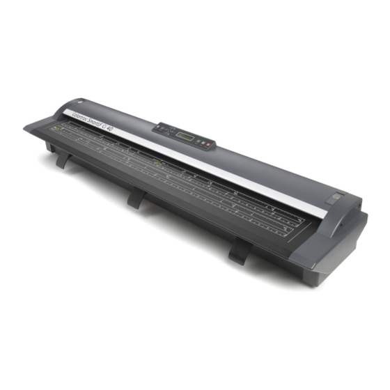
Related Manuals for Colortrac SmartLF Ci24m


Summary of Contents for Colortrac SmartLF Ci24m
- Page 1 CiTM Colortrac Ltd Page 1 of 20 Ci Main Board Issue 4 Date: 30/03/15 This is a confidential controlled document and is the property of Colortrac Ltd. It is not to be copied or reproduced in part or whole.
- Page 2 Technical Support, Colortrac Ltd. Colortrac Ltd shall not be liable for any damages, errors, issues or events that result from the use of the equipment or this manual. Page 2 of 20...
-
Page 3: Table Of Contents
Ci Instruction Manual Contents REPLACING MAIN BOARD ....................4 CONFIGURING MAIN BOARD TO A Ci24................16 RUNNING UTILITIES ......................17 NORMALISATION ......................... 19 AUTO STITCH ........................20 Page 3 of 20... -
Page 4: Replacing Main Board
‘motor speed’ as in Chapter 3 “Running Utilities”. NOTE: If the board is faulty so you can not run the utilities or the value is ‘9#000’, contact support (support@colortrac.com) for the correct value for this scanner, quoting the scanner serial number. 2. Disconnect the scanner. - Page 5 Ci Instruction Manual 4. Pull the Cable Tray Right Sub-A away from the chassis. 5. Remove the 4 x M3 pan head screws from the PCB Tray covering the Main Board. NOTE: The bottom right hand corner screw acts as an earth point.
- Page 6 Ci Instruction Manual 7. Disconnect the USB connection to the board to allow the PCB Tray to come off. 8. Disconnect the inline connector of the mains cable. NOTE: These cables go through the cover with suppressors, the wires are hard soldered on, and can be easily broken off, and so great care is needed when handling this cable.
- Page 7 Ci Instruction Manual 10. Disconnect the mains plug from the Main Board and remove the PCB Tray. For Ci24 11. For the Ci24 PCB Tray, remove the 4 x M3 screws in each corner. 12. Pull the PCB tray out gently, remembering the power cable is connected to the tray.
- Page 8 Ci Instruction Manual 13. Disconnect the inline connector for the power cable. 14. Disconnect the Power cable from the main board. 15. Disconnect all the remaining cables from the Main Board. Page 8 of 20...
- Page 9 Ci Instruction Manual 16. Release the locking plates holding the ribbon cables in place on all the connectors. NOTE: Too much force doing this could result in breaking the locking plates, so care is required. 17. Remove the 4 x M3 Pan Head Screw holding the Main Board in place.
- Page 10 Ci Instruction Manual 20. Using tweezers, push the CIS cables squarely back into the appropriate connectors. These cables are short to comply with EMC regulations. Take care not to damage the cables during insertion. Make sure the cable fits completely into the connector so that little or no silver is showing.
- Page 11 Ci Instruction Manual 23. Refit the ribbon cable to the control cable. Ci40 24. Refit the PCB Tray, hold the PCB Tray up in position, reconnect the main connector onto the main board, making sure it latches in place. 25. While refitting the PCB Tray, make sure that all the fitted cables are out of the way of any edges of the...
- Page 12 Ci Instruction Manual 26. Replace the 4 x M3 pan head screw to hold the cover on, remembering to fit the earth lead to the bottom right hand screw. 27. Reconnect the mains cable together, making sure the latch locks in place. 28.
- Page 13 Ci Instruction Manual 29. Refit the USB connector, pressing fully in. 30. Replace the Cable Tray Right Sub-A, making sure the left hand end is fed on first. Make sure the ribbon cable is not caught on the metal tray when fitting. 31.
- Page 14 Ci Instruction Manual Ci24 32. To refit the PCB Tray, reconnect the power cable into the main board. 33. Reconnect the inline power cable connector. 34. Reposition the PCB Tray, making sure that none of the cables are damaged or in the way.
- Page 15 Ci Instruction Manual 35. Replace the 4 x M3 screws in each corner of the PCB Tray. 36. Rotate the scanner back into position on the stand. 37. After powering up the scanner, go to the Set Parameters program as described in chapter 2 ‘Configuring Main Board’...
-
Page 16: Configuring Main Board To A Ci24
Ci Instruction Manual Always check the latest version of firmware/driver and utilities are installed. Download from http://www.colortrac.com/support/software-downloads/ if not. CONFIGURING MAIN BOARD 1. Go to support website and download and install the Ci www.colortracsupport.com Set Parameters Program login details (if un-known) available on request from support. -
Page 17: Running Utilities
Ci Instruction Manual RUNNING UTILITIES 1. Open the Ci Utilities program by double clicking on the icon on the desktop or start menu. 2. Right click in any part of the opening screen, and enter the password “pass” for the advanced utilities functions. - Page 18 Ci Instruction Manual 4. The Manual Stitch tab allows for manual adjustments to be made to the stitch values. Set Motor Speed. This can be adjusted by over writing a value and clicking ‘Set Motor Speed’. Note this value before removing the old Main board.
-
Page 19: Normalisation
Ci Instruction Manual NORMALISATION 1. Open Ci 40 utilities. 2. Insert the normalisation sheet, with the black end inserted first, face upwards. NOTE: If target is only white, insert matt side up. 3. Click “Full Normalisation”. This process takes approx. 1.5 minutes. -
Page 20: Auto Stitch
Ci Instruction Manual AUTO STITCH 1. Open Ci 40 utilities. 2. Insert the Auto Stitch target with the 2 x horizontal lines inserted first, face up. 3. Click “Auto Stitch”. This process takes a few minutes. Make sure the process is complete before shutting anything down or scanning.
Need help?
Do you have a question about the SmartLF Ci24m and is the answer not in the manual?
Questions and answers