HP 9000 rp3440 Installation Manual
Hide thumbs
Also See for 9000 rp3440:
- User's & service manual (254 pages) ,
- Service manual (210 pages) ,
- Operation and maintenance manual (180 pages)

Related Manuals for HP 9000 rp3440


Summary of Contents for HP 9000 rp3440
-
Page 1: Installation Guide
Installation Guide HP 9000 rp3410 and HP 9000 rp3440 Manufacturing Part Number: A7137-96001 Sixth Edition April 2005 U.S.A. © Copyright 2004-2005 Hewlett-Packard Development Company, L.P. -
Page 2: Legal Notices
The information contained herein is subject to change without notice. The only warranties for HP products and services are set forth in the express warranty statements accompanying such products and services. Nothing herein should be construed as constituting an additional... -
Page 3: Table Of Contents
Configuring the HP 9000 rp3410 or HP 9000 rp3440 Server ....... - Page 4 Contents Power and System LEDs ............74 LAN LEDs .
- Page 5 Figures Figure 1-1. HP 9000 rp3410 and HP 9000 rp3440 Server (front view) ..... . . 11 Figure 1-2. HP 9000 rp3410 and HP 9000 rp3440 Server (front view with bezel removed) ..11 Figure 1-3.
- Page 6 Figure 3-1. Control Panel LEDs ........... . . 74 Figure 4-1. HP 9000 rp3410 and HP 9000 rp3440 Server (rear view) ..... . . 79...
-
Page 7: Intended Audience
Printing History Intended Audience This document is intended to provide technical product and support information for authorized service providers, customer system administrators, and HP support personnel. What’s New? The layout of this document was changed to improve usability. Notational Conventions The following notational conventions are used in this publication. -
Page 8: Related Information
Example screen output is represented using this font. Reader Comments and Feedback HP welcomes your feedback on this publication. Please address your comments to edit@presskit.rsn.hp.com and note that you will not receive an immediate reply. All comments are appreciated. Related Information You can find other information on HP server hardware management, Microsoft®... - Page 9 • HP-UX Virtual Partitions http://www.hp.com/hpbooks/prentice/ptr_0130352128.html HP Books are available worldwide through bookstores, online booksellers, and office and computer stores. Printing History The Printing History below identifies the edition dates of this manual. Updates are made to this publication on an unscheduled, as needed, basis. The updates will consist of a complete replacement manual and pertinent on-line or CD-ROM documentation.
-
Page 11: Server Overview And Unpacking
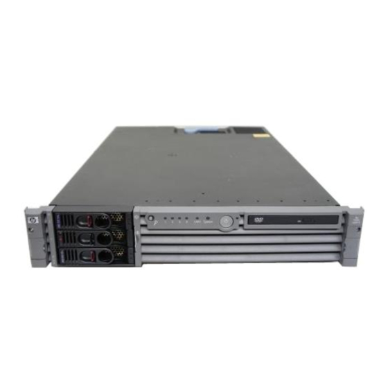
Server Overview The HP 9000 rp3410 server is a 1-way or 2-way, rack- or tower-mount server. Similarly, the HP 9000 rp3440 server is a 1-way, 2-way or 4-way, rack- or tower-mount server. Both of these servers are based on the PA-RISC processor family architecture. -
Page 12: Figure 1-3 Hp 9000 Rp3410 And Hp 9000 Rp3440 Server (Rear View)
Server Overview and Unpacking Server Overview Figure 1-3 HP 9000 rp3410 and HP 9000 rp3440 Server (rear view) Figure 1-4 HP 9000 rp3410 and HP 9000 rp3440 Server (tower version) Chapter 1... -
Page 13: Unpacking The Server
You must complete the form and return it to the shipping representative. Unpacking a Non-Racked Server NOTE HP recommends the use of a lifter, such as a RonI Company model 17000 SP 400 lifting device, when moving a non-racked system. Unloading with a Lifter To unload the server from the pallet using a lifter, perform the following steps: Use caution when using a lifter. -
Page 14: Installing The Hp Server Into A Rack
Installing the HP Server into a Rack HP Rack All HP 9000 rp3410 and HP 9000 rp3440 servers that are to be installed into racks are shipped with equipment mounting slides. With every set of slides comes an installation guide: Installation Guide, Mid-Weight Slide Kit, 5065-7291. -
Page 15: Installing And Configuring
Voltages may be present within the server. Many assemblies are sensitive to damage by electrostatic discharge. To ensure safe handling of components and to prevent injury to personnel, or damage to the HP server, adhere to the following procedures: •... -
Page 16: Service Tools Required
Installing and Configuring Service Tools Required • Handle accessory boards and components by the edges only. Do not touch any metal-edge connectors or any electrical components on accessory boards. Service Tools Required Service of this product may require one or more of the following tools: •... -
Page 17: Control Panel
Installing and Configuring Control Panel Control Panel The control panel of the HP 9000 rp3410 or HP 9000 rp3440 server provides the controls and indicators commonly used for operation. Figure 2-1 Front View Control Panel DVD Drive HDD 3 HDD 2... - Page 18 Momentarily (less than 1 second) has no effect For more than 1 second, but less than 5 seconds—do not use. This selection initiates e-buzzer functions that are not supported in the HP 9000 rp3410 and HP 9000 rp3440 servers For more than 5 seconds (and then released) causes an immediate and hard power down...
- Page 19 This function may be remotely activated. a. See the Troubleshooting chapter of this guide and refer to the HP 9000 rp3410 and HP 9000 rp3440 Operations Guide for details and information provided by the system LEDs.
-
Page 20: Additional Controls And Indicators
Additional Controls and Indicators The HP 9000 rp3410 or HP 9000 rp3440 server can have up to three low-voltage differential (LVD), 3.5 inch form factor hard disk drives (HDDs) installed. These hard disk drives have LEDs that provide status and activity information. -
Page 21: Optional Removable Media Drive
Additional Controls and Indicators Optional Removable Media Drive The HP 9000 rp3410 or HP 9000 rp3440 server is delivered without a removable media drive. Either a DVD-ROM or CD-RW/DVD-ROM drive may be added. Each of these optional devices has one activity LED. -
Page 22: Rear Panel
Rear Panel Rear Panel The HP 9000 rp3410 or HP 9000 rp3440 server rear panel includes communication ports, I/O ports, AC power connector, locator LED, and button. Additional LEDs located on the rear panel of the HP 9000 rp3410 or HP 9000 rp3440 server signal the operational status of: •... -
Page 23: 10/100/1000 Base-T Ethernet Lan Connector
Installing and Configuring Rear Panel Table 2-4 Rear Panel Connectors and Switches (Continued) Connector/Switch Function Locator button and The locator button and LED are used to help locate a server within a rack of servers. When the button is engaged, the blue LED illuminates and an additional blue LED on the front panel of the server illuminates. -
Page 24: Ilo Manageability Card Lan Leds
Installing and Configuring Rear Panel iLO Manageability Card LAN LEDs The iLO manageability card LAN uses an RJ-45 type connector. This connector has four LEDs that signal status and activity. Figure 2-7 iLO Manageability Card LAN LEDs Self-test 10BT 100BT Standby Power Table 2-6... -
Page 25: Removing And Replacing System Covers And Bezels
Accessing a Rack Mounted Server The HP 9000 rp3410 and HP 9000 rp3440 servers are designed to be rack mounted. The following procedure explains how to gain access to a server that is mounted in an approved rack. For slide installation instructions, refer to the Installation Guide, Mid-Weight Slide Kit, 5065-7291. -
Page 26: Figure 2-8 Release The Rack Latches
Installing and Configuring Removing and Replacing System Covers and Bezels Step 2. Release the rack latches by rotating them outward (Figure 2-8). Figure 2-8 Release the Rack Latches Step 3. Slide the system out of the rack until the guide-rail release clips are visible. Insert the Server into the Rack To insert the server into the rack, perform the following steps: Step 1. -
Page 27: Figure 2-9 Removing And Replacing The Metal Cover
Installing and Configuring Removing and Replacing System Covers and Bezels Step 2. Ensure the top cover lock keyswitch is in the unlocked position. Rotate the blue release lever toward the back of the system and slide the cover toward the back of the system (Figure 2-9). Figure 2-9 Removing and Replacing the Metal Cover Step 3. -
Page 28: Figure 2-10 Aligning The Metal Cover
Installing and Configuring Removing and Replacing System Covers and Bezels Step 1. Align the front edge of the cover with the alignment mark on the optical drive bay (Figure 2-10). Figure 2-10 Aligning the Metal Cover To replace cover, align front edge here then slide forward Step 2. -
Page 29: Figure 2-12 Front Bezel Retaining Clip
Installing and Configuring Removing and Replacing System Covers and Bezels Removing and Replacing the Front Bezel You must remove the front bezel from the chassis to gain access to the power supplies and optical drive. Removing the Front Bezel Step 1. Press in on the retaining clips located on the right-side of the front panel (Figure 2-12). Figure 2-12 Front Bezel Retaining Clip Step 2. -
Page 30: Tower Configuration
Installing and Configuring Removing and Replacing System Covers and Bezels Step 2. Close the bezel and push toward the front of the system until it locks into place (Figure 2-13). Figure 2-13 Replacing the Front Bezel Tower Configuration NOTE If you are replacing a hot-swappable item, you can leave the system on and external cables (including the power cord) connected. -
Page 31: Figure 2-14 Removing The Plastic Cover
Installing and Configuring Removing and Replacing System Covers and Bezels b. Lift the plastic cover off of the system chassis. Figure 2-14 Removing the Plastic Cover Removing the Metal Cover Step 1. Remove the metal cover. Figure 2-15 Removing the Metal Cover a. -
Page 32: Figure 2-16 Metal Cover Alignment Mark
Slide the cover toward the back of the chassis and lift the cover off (Figure 2-15). CAUTION The HP server depends on the access panels being closed for proper cooling of internal components. Operating the system with the cover removed can cause the system to quickly overheat. -
Page 33: Figure 2-17 Replacing The Metal Cover
Installing and Configuring Removing and Replacing System Covers and Bezels b. Place the metal cover on the chassis and slide it toward the front of the system until the blue release lever snaps in place (Figure 2-17). Figure 2-17 Replacing the Metal Cover Step 2. -
Page 34: Figure 2-19 Front Bezel
Installing and Configuring Removing and Replacing System Covers and Bezels Removing and Replacing Front Bezel You must remove the front bezel from the chassis to gain access to the power supplies and optical drive. Removing the Front Bezel To remove the front bezel parts, perform the following steps: Figure 2-19 Front Bezel Step 1. -
Page 35: Figure 2-20 Aligning The Tower Front Bezel
Installing and Configuring Removing and Replacing System Covers and Bezels To replace the front bezel parts, perform the following steps: Figure 2-20 Aligning the Tower Front Bezel Step 1. Position the bezel at an approximate 45 degree angle and align the retaining slots at the bottom with the retaining tabs on the chassis. -
Page 36: Installing Internal Hard Disk Drives
LVD HDD LVD HDD 1 Two additional hard disk drives may be added to your HP server in slots 2 and 3. Always use low profile disk drives (1.0" height) in your HP 9000 rp3410 and HP 9000 rp3440 servers. -
Page 37: Figure 2-22. Filler Removal From Slot 1
Installing and Configuring Installing Internal Hard Disk Drives Step 2. Remove the slot filler that is installed in the slot where the additional drive is to be installed. Figure 2-22 Filler Removal from Slot 1 Step 3. Slide the hard disk drive into the slot until it is seated. Figure 2-23 Disk Drive Installation in Slot 3 Step 4. -
Page 38: Figure 2-24 Hard Drive Lock
Use diagnostics provided by the offline diagnostic environment to exercise the module added Step 7. If rack-mounted, slide the HP server back into the rack until it stops. Step 8. Check the installation of the hard disk drive by powering on the server and checking the virtual front panel and system event log for correct status for the hard disk drive. -
Page 39: Installing A Dvd-Rom Drive
Failure to properly complete the steps in this procedure will result in erratic system behavior or system failure. For assistance with this procedure contact your local HP Authorized Service Provider. Figure 2-25... -
Page 40: Installing The Dvd-Rom Drive
Installing and Configuring Installing a DVD-ROM Drive Installing the DVD-ROM Drive To install a DVD-ROM drive, perform the following steps: Step 1. Turn off the system and disconnect power and external cables. Step 2. Remove the front bezel and cover. (See “Removing and Replacing System Covers and Bezels” on page 25.) Step 3. -
Page 41: Removing And Replacing Airflow Guides
Installing and Configuring Removing and Replacing Airflow Guides Removing and Replacing Airflow Guides You must remove airflow guides before installing processors or memory. The system has the following airflow guides: • The processor airflow guide ensures that the proper volume of air for cooling the dual processor module power pods, processor module(s), and voltage regulator module(s) flows over these components. -
Page 42: Removing And Replacing The Processor Airflow Guide
Installing and Configuring Removing and Replacing Airflow Guides Step 3. Grasp the memory airflow guide and lift it out of the system (Figure 2-27). Figure 2-27 Removing the Memory Airflow Guide Replacing the Memory Airflow Guide Step 1. Align the guides on both sides of the airflow guide with the slots on the chassis. Step 2. -
Page 43: Figure 2-28 Removing The Processor Airflow Guide
Installing and Configuring Removing and Replacing Airflow Guides b. At the same time, grasp the back end of the processor airflow guide and lift the guide out of the system (Figure 2-28). Figure 2-28 Removing the Processor Airflow Guide Chapter 2... -
Page 44: Figure 2-29 Removing Fans 1A And 1B
Installing and Configuring Removing and Replacing Airflow Guides Step 5. Grasp system fan 1A and lift it from its socket (Figure 2-29). Figure 2-29 Removing Fans 1A and 1B Fan 1A Fan 1B Step 6. Grasp system fan 1B and lift it from its socket (Figure 2-29). Step 7. -
Page 45: Figure 2-30 Open The Release Clip
Installing and Configuring Removing and Replacing Airflow Guides Step 8. Rotate the clip clockwise to release the latch (Figure 2-30). Figure 2-30 Open the Release Clip Step 9. Disconnect the power cable connected to the guide from the system board by squeezing the clips. Chapter 2... -
Page 46: Figure 2-31 Remove The Front Portion Of The Processor Airflow Guide
Installing and Configuring Removing and Replacing Airflow Guides Step 10. Lift the front portion of the processor airflow guide out of the system (Figure 2-31). Figure 2-31 Remove the Front Portion of the Processor Airflow Guide Replacing the Processor Airflow Guide Step 1. -
Page 47: Figure 2-32 Routing The Turbofan Power Cables Through Heatsink Posts
Installing and Configuring Removing and Replacing Airflow Guides Step 3. Route the processor turbo fan power cables through the processor heatsink posts so that the cables will not be pinched between the heatsink posts and the processor airflow guide (Figure 2-32). CAUTION Turbo fan power cables can be damaged if pinched between the heatsink posts and the processor airflow guide. -
Page 48: Installing Additional System Memory
Installing and Configuring Installing Additional System Memory Installing Additional System Memory Your system has 12 memory sockets for installing DDR SDRAM memory modules. System memory DIMMs are located on the system board. WARNING Ensure that the system is powered-down and all power sources have been disconnected from the server prior to removing or replacing system memory. -
Page 49: Supported Dimm Sizes
Supported DIMM Sizes Supported DIMM sizes are 256 MB, 512 MB, 1 GB, 2 GB (HP 9000 rp3440 only), and 4 GB (HP 9000 rp3440 only). If 4 GB DIMMs are used (HP 9000 rp3440), only one configuration (8 X 4 GB in the first eight sockets) is supported. -
Page 50: Installing System Memory
(groups of four). This allows memory configurations of four, eight, or twelve DIMMs. Thus, the HP 9000 rp3440 server must include a minimum of 1 GB and may include up to 24 GB of memory in combinations of 256 MB, 512 MB, 1 GB, and 2 GB DIMMs, or 32 GB of memory consisting of eight 4 GB DIMMs. - Page 51 System Firmware Requirements If you are using 4 GB DIMMs in a HP 9000 rp3440 server, system firmware must be greater than revision 44.24. Use the BCH command FV, or the MP command SR to display the system firmware revision status. If necessary, use the MP command SR to upgrade system firmware.
-
Page 52: Figure 2-34 Inserting Dimm Into Connector
Step 8. Reconnect all power and external cables and turn on the system. Step 9. Verify the memory installation by using the system utilities. (Refer to the Utilities chapter of the HP 9000 rp3410 and HP 9000 rp3440 Operations Guide for additional information.) •... -
Page 53: Removing And Replacing The Pci Card Cage
Installing and Configuring Removing and Replacing the PCI Card Cage Removing and Replacing the PCI Card Cage Accessory cards are installed in a removable PCI card cage. This section explains how to remove and replace the PCI card cage. Removal is required to install accessory cards. Removing the PCI Card Cage To remove the PCI card cage from the server, perform the following steps: Step 1. -
Page 54: Replacing The Pci Card Cage
Installing and Configuring Removing and Replacing the PCI Card Cage Step 4. Grasp the PCI card cage cover and slide it away from the bulkhead end of the cage, then lift the cover off (Figure 2-36). Figure 2-36 Removing the PCI Card Cage Cover Step 5. -
Page 55: Installing Pci Cards
Installing PCI Cards The server may contain up to 4 PCI cards. PCI cards are located in the PCI card cage. The HP 9000 rp3410 server provides two 64-bit, 133 MHz PCI-X card sockets as slots 1 and 2. The HP 9000 rp3440 server provides four 64-bit, 133 MHz PCI-X card sockets as slots 1 through 4. -
Page 56: Figure 2-37 Installing A Pci Card
Step 7. Replace the cover. (See “Removing and Replacing the Metal Cover” on page 26.) Step 8. Verify the PCI card installation by using the system utilities. (Refer to the Utilities chapter of the HP 9000 rp3410 and HP 9000 rp3440 Operations Guide for additional information.) •... -
Page 57: Installing An Additional Power Supply
(N+1) capability. The power supplies in the HP server are hot swappable; that is, if one power supply stops working or exhibits voltage problems, the remaining supply can support the system until the failed unit is replaced. A power supply can be removed and replaced without turning off the system on systems with two power supplies. -
Page 58: Figure 2-39 Replacing The Power Supply
Step 5. Verify that both power supply LEDs are lit. Step 6. Use the PS command of the MP to verify power supply operation. (Refer to the Utilities chapter of the HP 9000 rp3410 and HP 9000 rp3440 Operations Guide for additional information.) Chapter 2... -
Page 59: Installing An Additional Processor Module
The HP 9000 rp3410 server supports one processor socket. This socket will accept one dual processor module which contains two 800 MHz CPUs. The HP 9000 rp3410 server 1-way configuration includes two CPUs in a single module, but only one CPU is enabled. (The second CPU can be enabled as part of a server upgrade.) The HP 9000 rp3440 server supports two processor sockets. -
Page 60: Figure 2-40 Unlocking The Dual Processor Module Locking Mechanism
Installing and Configuring Installing an Additional Processor Module Step 5. Unlock the dual processor module locking mechanism using the CPU install tool (2.5mm Driver or Allen Wrench). Insert the tool into the hole that runs down through the edge of the heatsink and rotate the special processor tool 180 degrees counterclockwise. -
Page 61: Figure 2-41 Aligning The Processor Module
Installing and Configuring Installing an Additional Processor Module Step 7. Use the four locator posts on the heatsink and the turbo fan power cable to properly align the fan and dual processor module on the system board. The four locator posts will fit in locator holes on the system board processor module mount. -
Page 62: Figure 2-42 Locking The Dual Processor Module In Place
Installing and Configuring Installing an Additional Processor Module Step 8. Use the special CPU install tool (2.5mm driver or Allen Wrench) to lock the dual processor module in place on the system board. To do this, insert the CPU install tool into the hole that runs down the side of the heatsink and rotate it clockwise 180 degrees (Figure 2-42). -
Page 63: Figure 2-44 Secure The Captive Screws
Installing and Configuring Installing an Additional Processor Module Step 10. Screw in the four heatsink captive screws. Tighten the screws in a criss-cross pattern. Figure 2-44 Secure the Captive Screws CPU Install Tool (Torx T15) Step 11. Locate the two power pod module shims on the system board. (On systems delivered with only one dual processor module installed, the power module shims are held in place by screws with plastic spacers over the threads.) Remove the holding screws and discard the plastic spacers. -
Page 64: Figure 2-46 Aligning The Processor Module Power Pod
Installing and Configuring Installing an Additional Processor Module Step 12. Slide the power pod module on the system board’s metal mounting bracket so that the power pod module connector connects with its connector on the processor module (Figure 2-46). Figure 2-46 Aligning the Processor Module Power Pod Chapter 2... -
Page 65: Figure 2-47 Install The Processor Module Power Pod Mounting Screws
Installing and Configuring Installing an Additional Processor Module Step 13. Align the two mounting screw holes on the power pod module with the screw holes in the shims on the system board’s metal mounting bracket. Screw in the power pod module mounting screws (Figure 2-47). -
Page 66: Figure 2-48 Connecting The Power Pod Cable
Installing and Configuring Installing an Additional Processor Module Step 14. Connect the power pod cable to the power connector on the system board. Figure 2-48 Connecting the Power Pod Cable Chapter 2... -
Page 67: Figure 2-49 Routing The Turbofan Power Cables Through Heatsink Posts
Step 20. Reconnect power and external cables and turn on the system. Step 21. Verify processor installation by using the system utilities. (Refer to the Utilities chapter of the HP 9000 rp3410 and HP 9000 rp3440 Operations Guide for additional information.) •... -
Page 68: Replacing The System Battery
The system has two batteries. The main system battery is located on the system board. The other battery is located on the underside of the iLO manageability card. Refer to the Removing and Replacing Internal Components chapter of the HP 9000 rp3410 and HP 9000 rp3440 Maintenance Guide for additional information on the iLO manageability card battery. -
Page 69: Replacing The System Battery
Installing and Configuring Replacing the System Battery Replacing the System Battery Step 1. Turn off the system and disconnect power and external cables. Step 2. Remove the cover. (See “Removing and Replacing System Covers and Bezels” on page 25 for instructions.) Step 3. -
Page 70: Configuring The Hp 9000 Rp3410 Or Hp 9000 Rp3440 Server
Configuring the HP 9000 rp3410 or HP 9000 rp3440 Server Configuring the HP 9000 rp3410 or HP 9000 rp3440 Server Configuring the HP 9000 rp3410 or HP 9000 rp3440 server requires the use of the system utilities to set up user-desired configuration parameters. -
Page 71: Troubleshooting
Troubleshooting This chapter provides troubleshooting instructions for your HP 9000 rp3410 or HP 9000 rp3440 server. Information to Collect Before You Contact Support Before you contact HP support, you should: Step 1. Check information on troubleshooting and attempt to solve the problem. See Chapter 3, “Troubleshooting.”... -
Page 72: Troubleshooting Methodology
CAUTION Do not operate the HP server for more than 5 minutes with any cover (including disk drives) removed. If you are hot-swapping a fan, reinstall the cover within 5 minutes to prevent overheating. Damage to system components may result due to improper cooling airflow. - Page 73 No effect More than 1 second but Not used. This selection initiates E-buzzer less than 5 seconds functions that are not supported in the HP 9000 rp3410 and HP 9000 rp3440 servers More than 5 seconds Hard shutdown OS running...
-
Page 74: Troubleshooting Using Leds
Troubleshooting Troubleshooting Using LEDs Troubleshooting Using LEDs If you suspect a hardware failure during installation, the power and system LEDs, located on the front control panel, will help you identify the problem. The following sections describe their functions. You may want to back up your data or replace a component before it fails. -
Page 75: Lan Leds
Troubleshooting Troubleshooting Using LEDs For system alerts of levels 3–5, you can clear the attention condition on the LED by accessing the logs using the sl command available in the MP command mode. You can clear the fault condition for system alerts of level 7 by resolving the problem and cycling power. See the SL error logs for additional error information. - Page 76 Troubleshooting Troubleshooting Using LEDs Table 3-4 iLO Manageability Card LAN LEDs (Continued) LAN LED Location Color State No link or 10BT link Standby Bottom Green Standby power on Power Standby power off Chapter 3...
-
Page 77: Where To Get Help
The latest drivers and utilities • Additional documentation Phone Support To contact HP customer support by phone, go to the HP IT Resource Center (ITRC) near you, at http://www.itrc.hp.com. Local phone numbers are listed in your native language for help. Chapter 3... - Page 78 Troubleshooting Where to Get Help Chapter 3...
-
Page 79: Cable Connections
AC Input Power The HP 9000 rp3410 server has one power supply unit (PSU) installed in the front of the server. The HP 9000 rp3440 server comes with two PSUs installed in the front of the server. Each PSU has one AC input connector at the rear of the server. -
Page 80: Core I/O Connections
Cable Connections Core I/O Connections Core I/O Connections Each HP 9000 rp3410 and HP 9000 rp3440 server core I/O includes: • Four USB ports • Two 9-pin serial ports (Console A and Serial B—factory use only) • One Management Processor (MP) I/O interface —... -
Page 81: Management Processor (Mp)
Cable Connections Management Processor (MP) Management Processor (MP) Integrated Lights-Out (iLO) offers remote server management through an independent management processor (MP). It provides a way for you to connect to a server and perform administration or monitoring tasks for the server hardware. iLO is available whenever the system is connected to a power source, even if the server main power switch is in the off position. -
Page 82: Configuring The Mp Lan Port Ip Address
Advanced Pack features, such as SSH access, group actions capability, and LDAP NOTE A complete description of the MP is provided in the HP Integrity and HP 9000 Integrated Lights-Out Management Processor Operations Guide. Configuring the MP LAN Port IP Address By connecting the MP LAN port to an active network, you have two options for configuring an IP address. -
Page 83: Accessing The Management Processor
Cable Connections Management Processor (MP) Step 5. Click OK to close the Connection Setup window. Step 6. Pull down the Setup menu and choose Terminal (under the Emulation tab). Step 7. Choose a supported terminal type. The preferred type is VT100. Step 8. - Page 84 Console Rights (Operator) level user; login = Oper, password = Oper (both are case sensitive). For security reasons, HP recommends that you use the UC command during the initial logon session to modify default passwords (enter CM at the MP> prompt, and enter UC at the MP:CM>...
-
Page 85: Configuring The Management Processor Lan Information
Cable Connections Management Processor (MP) Configuring the Management Processor LAN Information LAN information includes the management processor network name, IP address information, and configuring DHCP and DNS service information. To configure the management processor LAN IP address: Step 1. At the MP Main Menu prompt (MP>), enter CM to choose command mode. Step 2. - Page 86 Cable Connections Management Processor (MP) The host name is not case sensitive. NOTE Step 7. The screen displays the current subnet mask name. When prompted to enter a new value or Q, enter the new subnet mask name. Step 8. The screen displays the current gateway address. When prompted to enter a new value or Q, enter the new gateway address.
- Page 87 Cable Connections Management Processor (MP) Web Console Port Number : 2023 SSH Access Port Number : 22 IPMI/LAN Port Number : 626 LAN status: UP and RUNNING -> Command successful. MP:CM> NOTE The SSH console port number does not display if you do not have Integrated Lights-Out Advanced Pack licensing.
-
Page 88: Mp Command Reference
Cable Connections Management Processor (MP) MP Command Reference There are two menus from which commands are executed: the MP Main Menu and the Command Menu. You access the Command Menu by first using the CM command at the MP> prompt. The following tables provide a reference for commands available through the command line interface. - Page 89 Cable Connections Management Processor (MP) Table 4-2 Command Menu Commands and Descriptions (Continued) Command Description Modify MP inactivity timers LAN configuration LDAP configuration LDAP License management Display and configure locator LED LAN status Modem reset Modem status Remote power control Paging parameter setup Power restore Power management module status...
-
Page 90: Booting The Server
Cable Connections Booting the Server Booting the Server To boot the server, press the power switch located to the left of the front panel LEDs. NOTE If the front bezel is attached and in the closed position, you will need to open the small door on the front bezel to gain access to the power switch. -
Page 91: Index
Rack, Installing Into iLO See also MP Reflection 1 Inspecting for Damage Remove and Replace Installing Additional Extend HP Server form Rack Internal Hard Disk Drive Memory Airflow Guide PCI and Graphics Cards PCI Card Cage Power Supply Processor Airflow Guide... - Page 92 Index configuring the MP LAN port set up local terminal access System LED System Memory, Installing terminal access Tools Tower Configuration Unpacking...
Need help?
Do you have a question about the 9000 rp3440 and is the answer not in the manual?
Questions and answers