Table of Contents
Advertisement
Quick Links
Advertisement
Table of Contents

Related Manuals for Teletek electronics AVA


Summary of Contents for Teletek electronics AVA
- Page 1 Wireless Security System INSTALLATION AND PROGRAMMING MANUAL 1304...
-
Page 2: Table Of Contents
3.1 Device Programming ..................20 3.1.1 Common Parameters ................21 3.1.2 Common Detector Parameters ............21 3.1.3 Programming of AVA P-Rex 100 TE Infrared Detectors .......23 3.1.4 Programming of МС 100 ТЕ Magnetic Contacts ........24 3.1.5 Programming of RC102 TE Remote Control ........26 3.1.6 Programming of SR200R Outdoor Siren ..........28... - Page 3 Table of Contents 3.6.5 Programming Backlight Turnoff Time and Generating of an Event for Mains Power Lost ..................45 3.6.6 System Option Programming ...............45 3.6.7 Software Version ..................45 3.6.8 Changing the Menu Language .............45 3.7 Service Menu....................46 3.8 Digital Communicator (Dialer) Programming ..........46 3.8.1 Telefphone Numbers Programming ............47 3.8.2 Event Messages Programming ............48 3.8.3 Dialer Options Programming ..............49...
-
Page 4: General Information
In addition the panel and the repeater have two wire zones and four programmable outputs (PGM) each. Figure 1. AVA control panel and the different wireless devices which could be enrolled into the system configuration. -
Page 5: Supported Wireless Devices
The Arm and Disarm functions can be activated via the 16 user codes from the control panel keypad, the wireless keyboard or from the remote control. The AVA Wireless System supports three types of panic functions, which can be activated from the control panel keypad, the remote control or from the wireless keyboard. -
Page 6: Control Panel Keyboard
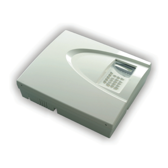
1. General Information 1.3 Control Panel Keyboard The main panel keyboard consists Display of an LCD Display, LED Indication buttons with general and special functions. A beep is Indication generated acknowledge pressing of any button. A sound Microphone signal is also used to indicate where a specific operation is accepted or rejected. -
Page 7: Buttons Functions
1. General Information 1.3.2 Button Functions 1.3.3 Display The AVA Wireless System avails of an alphanumeric display (2 x 16 characters). The following specific symbols have been introduced to account for various events: premises In normal working mode time and date are displayed and the user can choose from between two screens - Screen 1 with information of groups status, set by default and Screen 2. -
Page 8: Symbols Used For Text Entering From The Keypad
“Chime” - activated entry-exit zone. 1.3.6 Built-in Siren The AVA Wireless Security System has a built-in siren 90dB which could be freely programmed to become active in case of specific system events and continuity of siren alarm. For details when programming the built-in siren parameters see §3.6.2 Built-in... -
Page 9: System Installation
In order to achieve the best efficiency of the wireless system, prior to installation plan the location of the control panel and the wireless devices within the premises. The AVA Wireless System communicates two-way with all enrolled devices and therefore it is advised to observe the following recommendations when selecting the installation location. - Page 10 2. System Installation 3. No objects or obstructions, which may reflect or absorb radio waves, as well as devices causing interferences, must be situated in close proximity of the control panel installation location – Figure. 6. Figure 6. Do not install the panel close to sources of strong radio fields as these can cause interference and thus diminish the serviceability of the system and its radio band.
-
Page 11: Control Panel Installation
Magnet Panel Contact М 100 Е Remote Control RC 102 TE Figure 8. A model situation of locating the AVA Control Panel and the wireless devices enrolled in it. Fire Detector PIR Detector LEGEND: Magnet Contact Control Panel Figure 9. Location of the AVA Control Panel and the wireless devices enrolled in it within the premises. -
Page 12: Box Mounting
2. System Installation 2.2.2 Box Installation 1. Use the provided profile board (see Template the back of the packaging) to drill mounting openings (6 - 8 mm) at the installation location - Figure 10. For mounting onto a brick wall it is recommended to use 4,2x35 DIN 7981 screws and 6x30 UN 9802 plugs. - Page 13 #NP-12 model) designed to provide backup power supply in case of mains failure (230V AC). NOTE that the battery has to be connected to the AVA control module AFTER the initial system start-up - see §2.3, page 15. Observe the polarity of the battery terminals. Otherwise the self-recoverable fuse BATT will turn out.
-
Page 14: Connecting Wire Zones And Programmable Outputs
Dialer connecting Connect the Dialer to the AVA control panel only when the main power supply is switched off. The Dialer has to be the first device connected to the telephone line, in order to provide it with highest priority in operation. -
Page 15: Initial Start-Up Of The Control Panel
Place the top cover and wind the screws to the end, as shown in Figure 17. After performing a full system reset AVA system will automatically go on normal working mode and a sound signalization for open tamper in the... -
Page 16: System Programming Sequence
2. System Installation 2.4. System Programming Sequence After installing the AVA Wireless Alarm System control panel and performing a full reset, there shall be no enrolled system devices, and its system parameters shall be set at default values (for more information see also the Appendix: General Structure of System Menus). -
Page 17: Installing Wireless Devices
The Control Panel communicates with the wireless devices via a two-way radio connection. In order for an AVA System to communicate with the wireless devices, they must first be enrolled in the system so that it can identify them. Every wireless device has a unique house address (HA) with which it is memorized in the configuration of the system. - Page 18 2. System Installation Example for enrolling a wireless device - infrared detector:...
-
Page 19: Deleting The House Address Of A Device
Every wireless device communicates with the control panel within the authority of its unique house address (HA). In order for a specific device to be enrolled in an AVA control panel, it must not have an HA, which has been attributed from another system, i.e. -
Page 20: Programming
3. Programming 3. Programming System parameters programming is not required. Every added device adopt’s a default parameters which ensures the normal function of the system - see The Appendix: General Structure of System Menus. The installer avails of the opportunity to programme them further depending on the specific installation. -
Page 21: Common Detector Parameters
3. Programming Two submenus can be programmed here. open 1)Common Prog. 1)LED config ÒÕ / RX 1)LED config open programming 5min/1s/10times 10min/2s/5times 1)Common Prog. 2)Communication 20min/5s/5times 2)Communication 5min/1s/10times 60min/2s/5times Programme three parameters to specify what the wireless de- 1)LED config vice LEDs should indicate. - Page 22 3. Programming 2. From the screen of each device press the button to enter its parameter program- ming submenu. dNXXX ---#000000 DevicedN name Three submenus can be programmed here. Device01 name 1)Change name 1)Change name Device01 name Device01 name Device01 name disable? enable? 2)Enable/Disable...
-
Page 23: Programming Of Ava P-Rex 100 Te Infrared Detectors
3. Programming 3.1.3 Programming of AVA P-Rex Infrared Detectors Use the buttons to select the next menu from the 2)Program Device: 2)Program Device 2)Program Device 1)Common Prog. 3)PIRs This is the menu for scrolling through and programming the parameters of all available in the system infrared detectors. -
Page 24: Programming Of Мс 100 Те Magnetic Contacts
3. Programming The menu allows for detector sensitivity adjustments. The 1)Sensitivity values that can be selected are between 00 and 07, where the greater number shall be of higher sensitivity. The preset default value is 03. Reference to a group of sensors. 2)Device Group NOTE: By default the first enrolled in the system device shall be assigned to Group 1, the second to Group 2 and every next... - Page 25 3. Programming MC01 1)Impulse Input 1)Impulse Input counter:009 MC01 2)Device Group 2)Device Group N:02 MC01 3)Change name 3)Change name MC01 enable? MC01 MC01 disable? 4)Enable/Disable ENABLED MC01 MC01 are you sure? 5)Remove remove? not used -4 degree Ñ -2 degree Ñ MC01 6)LowTemperature 0 degree Ñ...
-
Page 26: Programming Of Rc102 Te Remote Control
3. Programming 3.1.5 Programming of RC102 TE Remote Control The AVA Wireless System can be controlled (armed/disarmed or have various types of alarm functions) through RC 102 TE Remote Control. The remote control has four but- tons with attributed default functions but can be further programmed from the control panel. - Page 27 3. Programming REM01 1)button 1 1)button 1 not programmed Arm f-n 1 Arm f-n Arm f-n Arm f-n REM01 2)button 2 Arm f-n 2)button 2 not programmed Arm f-n DisArm f-n 1 DisArm f-n 2 DisArm f-n 3 REM01 3)button 3 DisArm f-n 4 DisArm f-n 5 3)button 3...
-
Page 28: Programming Of Sr200R Outdoor Siren
3. Programming 3.1.6 Programming of SR200R Outdoor Siren Use the buttons to select the next menu from the 2)Program Device: 2)Program Device 2)Program Device 1)Common Prog. 6)Siren This is the menu for scrolling through and programming the parameters of all available in the system sirens. -
Page 29: Programming Of Fd 100 Te Fire Detector
3. Programming Siren activating events are selected in this menu. By default 1)Audible Events there are no programmed activating events. Programming is done by pressing the button, as described in §3 on page Two beeps will be emitted for full Arming when selecting the sqwk. - Page 30 3. Programming FIRE01 1)Sensitivity normal 1)Sensitivity normal high FIRE01 2)Fire Group 2)Fire Group N:06 FIRE01 3)Change name 3)Change name FIRE01 enable? FIRE01 FIRE01 disable? 4)Enable/Disable ENABLED FIRE01 FIRE01 are you sure? 5)Remove remove? not used -4 degree Ñ -2 degree Ñ FIRE01 6)LowTemperature 0 degree Ñ...
-
Page 31: Programming Of Wireless Ava Keyboard (Vg)
3. Programming 3.1.8 Programming of AVA Keyboard (VG) Wireless Keyboard Use the buttons to select the next menu from the 2)Program Device: 2)Program Device 2)Program Device 1)Common Prog. 8)Remote KBD This is the menu for scrolling through and programming the parameters of all available in the system wireless keyboards. -
Page 32: Programming Of Wire Detectors
3. Programming 3.1.9 Programming of Wire Detectors Use the buttons to select the next menu from the 2)Program Device: 2)Program Device 2)Program Device 1)Common Prog. 9)Wire Devices This is the menu for scrolling through and programming the parameters of all available in the system wire detectors. - Page 33 3. Programming In the 9)Wire Devices menu use the buttons to select the second 2)Programm W.Dev. sub menu. 9)Wire Devices 2)Program W.Dev. 13WIR ---#000000 Device13 name Device13 name 1)Device Group 1)Device Group N:00 Device13 name 2)Wire Input 2)Wire Input N:01 The group and the wire input, from which information will be provided, can be pro- grammed in the 2)Program W.Dev.
-
Page 34: Programming Of Repeater
6. Connect the accumulator battery to the AVA control panel as observe the polarity. 7. Close the device box, and be sure that the inclosure presses the tamper switch closed. - Page 35 3. Programming 1. The various enrolled and recorded in the system repeater-modules can be scrolled through with the help of the buttons. 14REP ---#002345 15REP ---#003456 Example: Repeater01 Repeater02 The first repeater-module (Repeater01) in this example is recorded as the fourteenth system device (14REP) and the second (Repeater02) as the fifteenth (15REP).
-
Page 36: Functions Programming
Engineer Menu 3)Functions The AVA Wireless System is controlled by the User with the help of Arm and Disarm func- tions. The system avails of six possible functions for Arming and six for Disarming. The groups (see §3.4) to be Armed / Disarmed are programmed for every individual function, as well as for the actions and the programmable outputs that will carry them out. -
Page 37: Disarming Functions Programming
3. Programming Programming is done by selecting the button, as described 1)Group options in §3 on page 20. Specify in the submenu which detector groups are to be armed by the programmed function. By default Function 1 has been programmed to arm Groups 1, 2 and 3 and Function 2 –... -
Page 38: User Programming
3. Programming 3.3 User Programming Engineer Menu Engineer code - 7777 Engineer Menu )Codes Menu The system supports 16 user codes with a 16 symbol name and parameters and one engineer code with all programming rights. From the engineer code menu can not be changed the User’s codes and their rights to bypass zones. -
Page 39: Changing The Engineer Code
3. Programming The attributes have the following meanings: Manager - holds permission to programme all remaining codes Bypass - holds permission to bypass zones Log view - holds permission to view event log-file Time/Date Set - holds permission to set date and time Remote Access - has enabled access to telephone line Use the button to confirm all entered data. -
Page 40: Detector Groups Programming
3. Programming 3.4 Programming Detector Groups Engineer Menu Engineer code- 7777 Engineer Menu 5)Group The system provides flexible organization of the different sensor groups which can be Armed/Disarmed with the help of functions. For better clarity we shall illustrate how the groups are determined with the example given in Figure 9, page 11 in the beginning of this manual. - Page 41 3. Programming Programming Arm/Disarm Functions With the help of the Arm/Disarm functions the system provides full or partial Arming/Dis- arming. Arming function 1 – Arms Groups 1, 2 and 3 (full arm) Arming function 2 – Arms Group 2 (partial arm) Arming function 3 –...
-
Page 42: Outputs Programming
3. Programming 3.5 Outputs Programming Engineer Menu Engineer code - 7777 Engineer Menu 6)Outputs In order to indicate (usually to external devices) certain system events (see Table of events) or trouble, all programmable outputs (PGM1-PGM4) can be programmed sepa- rately from the functions. Several events can be programmed simultaneously as a “logi- cal OR”... -
Page 43: System Parameters Programming
3. Programming 3.6 System Parameters programming Engineer Menu Engineer code - 7777 Engineer Menu 7)System The menu allows programming of a variety of different system parameters which are common to the system. To access the System Parameters menu select: Engineer code - 7777 Use the buttons to scroll through the different sub menus of the System Pa-... -
Page 44: Built-In Parameters Programming
3. Programming 3.6.2 Built-in Siren Parameters Programming 7)System 2)Main Siren * Alarm * FIRE - Tamper 2)Main Siren 1)System Events - Panic - Module Lost 1)System Events * Alarm - Medical * sqwk.on fARM * sqwk.on pARM 1 minute 2)Main Siren 2)Cut-Off time 2 minune 3 minute... -
Page 45: Programming Backlight Turnoff Time And Generating Of An Event For Mains Power Lost
The system software version can be seen in the menu. 7)System 7)Soft. Version 7)Soft. Version ver.:ÕÕ 3.6.8 Language Menu The AVA Control Panel supports different languages for the system menu. By default the menus are in English. 7)System 8)Language 8)Language english Use the button to confirm the entered language. -
Page 46: Service Menu
3. Programming 3.7 Service Menu The service menu is programmed and used ONLY by authorized personnel of the producer! 3.8 Communicator (Dialer) Programming Engineer Menu Engineer code - 7777 Engineer Menu 9)Dialer The communicator is designed to be installed in the wireless system box and has the following basic functions: 1. -
Page 47: Telefphone Numbers Programming
3. Programming 3.8.1 Telephone Numbers Programming 9)Dialer 1)Phones 1)Phones 1)Phones Phone 01 Phone 06 Button Phone 01 1)Enter Phone P T D 1)Enter Phone Phone 01 2)Choose Dest. 2)Choose Dest. Dest.(1-4) 01 Phone 01 3)Choose Prot. ContactID 3)Choose Prot. User Button Phone 01 4)Enter ID... -
Page 48: Event Messages Programming
3. Programming For telephones 1 to 6 is assigned a number for a Destination from 2)Choose Dest. 1 to 4 where 1 means top dialling priority and 4 is the lowest prior- ity. Any message (about an event) is transmitted individually to one of the four Destinations;... -
Page 49: Dialer Options Programming
3. Programming 3.8.3 Dialer Properties Programming 9)Dialer 3)Dialer Prop 3)Dialer Prop 1)Dest Attempt 1)Dest Attempt Count(1-9) 02 3)Dialer Prop 2)Max Attempt 2)Max Attempt Count(1-9) 04 3)Dialer Prop 3)Line break 3)Line break min(0-99) 15 - Call Back - Ans Mashine 3)Dialer Prop 4)Common flags - Wait Dialtone 4)Common flags... - Page 50 3. Programming Set the maximum number of attempts to transmit an event to a 2)Max Attempt central station or to an individual user in this menu. After the com- municator is reset, the default value is 4. After listing in order of priority the 4 Destinations, the dialling attempts are renewed after listing the 4 destinations in a priority order, set in the “Max At- tempt”...
- Page 51 3. Programming Introduce a telephone line fault warning indication delay. The 3)Line break time is set in minutes. The availability of a telephone line is not tested if the preset value is 0. After resetting the communicator the preset default value is 15 minutes. Set the options for the performance of the dialer in this menu.
-
Page 52: Pc Connection Programming
3. Programming 3.8.4 PC Connection Programming 9)Dialer 4)Udl 4)Udl 1)Id Panel 1)Id Panel 1234 4)Udl 2)Id PC 2)Id PC 1234 Button 4)Udl 3)Callback Ph 3)Callback Ph P T D No Answer 4)Udl 4)Answer mode modem DTMF cntrl 4)Answer mode No Answer 4)Udl 5)Rings 5)Rings... -
Page 53: Control Parameters Programming
3. Programming When answering the telephone select the type of signal from the 4)Answer mode menu. The possible options are: “Modem” - after the telephone is answered the system will ex- pect to be connected to a UDL computer. “DTMF cntrl” - the system will expect human control over DTMF-tones with listening, talking and control options over the communicator. -
Page 54: Alarm System Control By Telephone
3. Programming The destinations to which a test message is to be sent is set in 2)Send Test Msg the menu. Programming is done as described in §3. There is no default preset Destination. The menu sets the type of signal which is to be activated when 3)Pick UP answering the telephone. - Page 55 Button Listening to the AVA’s premises Button Talking to the AVA’s premises Button Listening and talking to the AVA’s premises Button Amplified listening to the AVA’s premises *9 - Remote Arming / Disarming mode 99 - Termination of the connection...
-
Page 56: Maintenance Menu
3. Programming 3.9 Maintenance Menu Engineer Menu Engineer code - 7777 Engineer Menu 1)Maintenance This is the first menu in the tree structure of the system software. It is in supplementary to the engineer-installer, where the various system parameters can be verified. Engineer Menu 1)Maintenance * ÀÑ... - Page 57 3. Programming The screen lists in 1 - 2 sec. all currently available system trou- 1)SystemTroubles ble. The possible trouble can be: AC lost - the panel does not register any power supply; main BATT - trouble with main battery; fuse - faulty fuse in auxiliary power supply;...
-
Page 58: Event Log
5. Events LOG 4.Events LOG Event DESCRIPTION OF THE EVENT ContactID Default programming by destinations Number IN THE LOG-FILE Protocol Protocol EV_ERROR EV_BURG_ALARM ВА EV_BURG_ALARM_REST ВН 130г EV_FIRE EV_FIRE_REST 110г EV_PANIC EV_PANIC_REST 120г EV_TAMPER EV_TAMPER_REST 137г EV_MEDICAL EV_MEDICAL_REST 100г EV_SENSOR_BPS EV_SENSOR_BPS_R 570г... -
Page 59: Electrical Specifications
- 2А Supplementary voltage PGM (+12V) fuse - 1A Dimensions of the AVA Control Panel Box - 293 х 340 x 102 mm 5.2 Electrical Specifications of a Repeater Module Power Supply: - Main power supply - ~230V AC ±10%, 50-60Hz - Backup Battery - 12V, 1.2 ÷... -
Page 60: Additional Spare Parts Kit
5.Electrical Specifications 5.3 Other Specifications Expected Battery Life for Wireless Devices: - Infrared detector - up to 2 years - Magnetic contact - up to 3 years - Remote control - up to 3 years (at 40-50 activations per a day) - Outdoor siren - up to 4 years - Wireless keyboard... -
Page 61: Declaration Of Comformity
7. Declaration of Conformity 7. Declaration of Conformity... -
Page 62: Notes
NOTES... -
Page 63: Guarantee
GUARANTEE During the guarantee period the manufacturer shall, at its sole discretion, replace or repair any defective product when it is returned to the factory. All parts replaced and/or repaired shall be covered for the remainder of the original guarantee, or for ninety (90) days, whichever period is longer. - Page 64 Address: 14А Srebarna Str., 1407 Sofia, Bulgaria Tel.: (+359 2) 9694 700, Fax: (+359 2) 962 52 13 e-mail: info@teletek-electronics.bg...
Need help?
Do you have a question about the AVA and is the answer not in the manual?
Questions and answers