Table of Contents
Advertisement
Quick Links
ATTENTION: Read carefully this installation Instructions before installing the device!
This manual is subject to change without notice!
1. General Description
Natron WE-C is a wireless expander (network gateway) module designed for operation with
conventional fire alarm panels, including MAG series panel, produced by Teletek Electronics JSC.
Natron WE-C is powered from external power supply with back-up battery. The module is
equipped with special inputs for monitoring the main and back-up power supplies.
Natron WE-C communicates with Natron series wireless devices enrolled to its configuration. Up
to 32 wireless devices can be enrolled to a specific expander (network gateway) module, forming
a linear network. Up to 5 Natron WE-C modules can be connected to a single conventional fire
alarm control panel as this depends on the system/panel capacity.
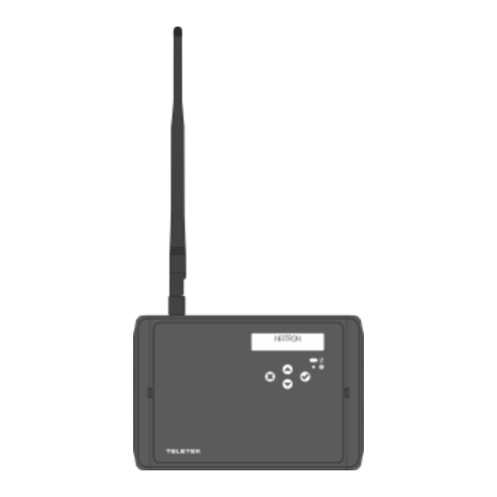
Natron WE-C is mounted in a compact plastic enclosure box suitable for wall mounting. The
information of the status of the enrolled wireless devices is presented on a LCD text display. The
programming of the wireless devices parameters is from the module menus.
A dipole SMA type antenna is supplied with the expander (network gateway) module to ensure
wide covering range and stable communication with the enrolled wireless devices.
2. Functional Features
• Specially designed for extending the application of conventional fire alarm panels
• Direct connection to conventional zone terminal
• Compatible for operation with MAG series and third-party conventional fire alarm control
panels
• Up to 5 wireless expanders (network gateway) modules to conventional panel/building*
• Up to 32** NATRON series wireless devices enrolled to a single Natron WE-C module
• Dipole antenna, SMA connector type
• Event messages for wireless device status: low battery, tamper, lost device
• Menu for reviewing the signal strength of the enrolled devices
• LCD display, dot matrix 16x2
• Multilanguage menus
• Standards applied: EN 54-18; EN 54-25
* The number depends on the type of the conventional panel and the capacity of the system.
** The number of enrolled NATRON devices depends on the number of the current connected wired devices to
the conventional zone. Up to 32 wired and wireless detectors can be connected to a conventional zone.
Natron WE-C
Conventional fire alarm wireless
expander (network gateway) module
23
2918
DoP No: 229
EN 54-18:2005
EN 54-18:2005/AC:2007
EN 54-25:2008
Address: 2 Iliyansko Shose Str,
1
Teletek Electronics JSC
1220 Sofia, Bulgaria
Advertisement
Table of Contents

Related Manuals for Teletek electronics Natron WE-C


Summary of Contents for Teletek electronics Natron WE-C
- Page 1 32 wireless devices can be enrolled to a specific expander (network gateway) module, forming a linear network. Up to 5 Natron WE-C modules can be connected to a single conventional fire alarm control panel as this depends on the system/panel capacity.
-
Page 2: Technical Specifications
4. Installation Place and Mounting It is strongly recommended to design the Natron wireless system in advance on paper, before starting the installation. Natron WE-C expander (network gateway) module should be installed at 2-2.5m above the floor level. Attention: Avoid installation of Natron WE-C module and the wireless devices near to: •... - Page 3 General View and Dimensions Opening the enclosure box Mounting holes Positioning of the antenna Use fixing elements according the mounting surface Openings for running cables For achieving the best signal strength and coverage it is recommended the antenna to be mounted in straight up position! There are two openings for running cables The SMA antenna is mounted to the module...
-
Page 4: System Topology
The enrolled to the module Natron series devices, operate in linear network. Up to 5 separate Natron WE-C modules can be connected to single conventional panel. The number of connected wireless modules depends on the system/panel capacity. - Page 5 6. PCB Elements To access the PCB of the module, open the enclosure box (follow the steps described in item 4). The PCB is factory mounted at the back side of the front cover. 1 - Terminals for connecting the conventional zone line - item 7.2. 2 - Terminals for connecting the sounders’...
- Page 6 7.1 Power Supply Unit Natron WE-C is powered only from an external power supply unit 24V DC. The power supply terminals are connected to ±PW terminals of Natron WE-C as observing the polarity. Natron WE-C is equipped with a special input “Inp” for Fault monitoring of the external power supply unit.
- Page 7 7.4 Zone Alarm EOL Resistors The zone alarm EOL resistors must be always installed at “Fire MCP” and “Fire Dev” terminals at Natron WE-C module. The value of the resistors is calculated according the operation voltage of the conventional zone and the fire alarm threshold current of the used manual call points and fire alarm detectors.
-
Page 8: Front Panel
2. Open the enclosure box of the expander (network gateway) module and mount it on the place of installation – see item 4. 3. Connect Natron WE-C module at the end of the conventional zone line and at the end of sounders circuit – see item 7. - Page 9 At normal operation mode, the screen of Natron WE-C is switched off. Pressing any of the operation buttons will activate the screen, as according the current state of the module, NATRON text or fault/warning message will appear.
- Page 10 6. In case of successful enrolment, the LEDs of the device flash 3 times in green, the message DONE appears on the screen and then the module automatically moves to the next free address in the list. The enrolled wireless device is added to the list with its specific type. 7.
- Page 11 4. The device will respond with activated indication and signalization depending on its type: Device Type Signalization Action Heat detector LEDs are flashing in orange Optical-smoke detector LEDs accompanied with short sound signals. Combined detector Sound LEDs are flashing accompanied with Sounder with strobe short sound signals.
- Page 12 14.2 Menu for Enable/Disable of Buzzer In the menu the installer can perform Enabling/Disabling of the operation of the built-in buzzer in Natron fire alarm detectors – TD, SD and MD. The buzzer is used for finding the physical place of installation of a detector, and is activated in case of fire alarm event together with the other sounders in the system.
- Page 13 660Hz 0.15s ON/0.15s OFF 510Hz, 0.25s/ 610Hz, 0.25s 800/1000Hz 0.5s each (1Hz) 250Hz - 1200Hz @ 12Hz 500Hz - 1200Hz @ 0.33Hz 2400Hz - 2900Hz @ 9Hz 2400Hz - 2900Hz @ 3Hz; 2500Hz (main sound frequency) 800Hz - 970Hz @ 100Hz 800Hz - 970Hz @ 9Hz 800Hz - 970Hz @ 3Hz 800Hz, 0.25s ON/1s OFF...
-
Page 14: Channel Setup
17. Setting the Language The menus of Natron WE-C expander (network gateway) module are available in different languages. To change the language of the menus, enter programming mode and scroll to 7. LANGUAGE menu. Press ENTER button. Use the arrow buttons to review the languages. The currently displayed language will be automatically set when you exit the menu with CANCEL button. - Page 15 The meaning of the displayed messages is as follows: Message Type Description The message is with the highest priority and is displayed in case if fire alarm event – activation of wireless fire detector or call Fire Alarm Alarm point. There is no communication between the expander (network gateway) module and a wireless device.
- Page 16 19. General Connection Diagram of Natron WE-C 18021250, RevB, 07/2023...
Need help?
Do you have a question about the Natron WE-C and is the answer not in the manual?
Questions and answers