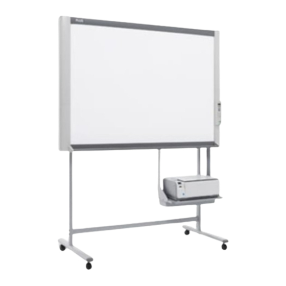
Plus M-12 Series Copyboard Assembly And Setup Manual

Plus M-12 Series Copyboard Assembly And Setup Manual

Captureboard

Advertisement

Quick Links

M-12 Series Copyboard / C-12 Series Captureboard
Assembly and Setup Manual
This is the installation and assembly manual for the M-12 series Copyboard and C-12
series Captureboard.
(The copyboard and/or captureboard are referred to as "the set" or "the main unit" in this manual.)
To the Customer
Special skills are required to install the set. Never try to assemble the
set yourself.
To the Dealer or Installation Tradesman
In the interest of the safety of the customer, please perform installation
work paying due attention to the strength of the installation location to
ensure that it can bear the load of the main unit, printer, and installation
parts.
1. Please Read in the Interest of Safety ....................................................... 2
2. Packaging List ............................................................................................ 3
3. Installation Procedure ............................................................................... 4
4. Assembly of the stand ................................................................................ 4
5. Wall Mounting ............................................................................................. 7
6. Assembly of the Printer Table ................................................................. 10
7. Connection to the set .............................................................................. 12
8. Test Print ................................................................................................... 17
9. Changing the Height of the Unit ............................................................. 18

TABLE OF CONTENTS

Advertisement

Table of Contents
loading
Need help?

Need help?

Do you have a question about the M-12 Series Copyboard and is the answer not in the manual?

Questions and answers

Summary of Contents for Plus M-12 Series Copyboard

  • Page 1: Table Of Contents

    M-12 Series Copyboard / C-12 Series Captureboard Assembly and Setup Manual This is the installation and assembly manual for the M-12 series Copyboard and C-12 series Captureboard. (The copyboard and/or captureboard are referred to as "the set" or "the main unit" in this manual.) To the Customer Special skills are required to install the set.
  • Page 2: Please Read In The Interest Of Safety

    1. PLEASE READ IN THE INTEREST OF SAFETY Warning • If you are not a qualifi ed assembly serviceperson, do not perform installation procedures. • Please be sure to perform the installation and assembly based on this manual. Incorrect installation or assembly will be the cause of injury.
  • Page 3: Packaging List

    2. PACKAGING LIST The packaged contents will differ depending on the purchased Series. Please open the carton and check the parts. In the rare event that something is missing, please contact your store of purchase. ■ List of Items in Package Main unit: 1 unit (standard type or wide type) Wall mounting brackets: ×...
  • Page 4: Installation Procedure

    3. INSTALLATION PROCEDURE The installation method will change depending on the type of installation. Please perform installation and assembly according to the following procedures. See Page 4 4. Assembly of the stand * The stand may be an option. * The printer may be sold separately. See Page 10 6.
  • Page 5 4. ASSEMBLY OF THE STAND (4) Attach the two horizontal bars to the T-shape legs. Use hexagonal socket screws (M5) and flat wash- Horizontal bar ers (M5) to attach. Partially fasten using the hexagonal wrench (M5), then T-shaped leg tighten securely after the upper and lower horizontal bars have been attached.
  • Page 6 4. ASSEMBLY OF THE STAND (7) Install the stay to the printer table. Insert the nylon bushing into the stay. Stay Nylon bushing Insert the stay into the pipe of the stand. Mount the stay to the printer table using two M3 screws. Notice Check again that the grooves in the stand’s hooks are se- curely inserted in the mounting holes in the support fi...
  • Page 7: Wall Mounting

    5. WALL MOUNTING (1) Determining the installation location 1200 mm The diagram indicates the dimensions of the installa- tion positions. The installation position is the same for both the standard type and the wide type. The installation of the main unit to the wall is per- formed after the printer table is assembled and at- tached to the main unit.
  • Page 8 5. WALL MOUNTING (2) Stick the cushions on the printer table, then mount the printer table on the main unit. Peel off the protective sheets from the cushions’ adhesive surfaces. Stick the cushions (2) on the back of the bracket. Protective sheet on adhesive surface Cushion...
  • Page 9 5. WALL MOUNTING (4) Attaching and anchoring the main unit to a wall or wall support fi tting. (The anchoring method will differ depending on the wall mounting method.) Installing on a Concrete Wall Anchor nut, etc. M6 screw Mounting to a Post M6 wood screw...
  • Page 10: Assembly Of The Printer Table

    6. ASSEMBLY OF THE PRINTER TABLE The printer table can be installed at either the left or right side. The installation method is the same. Determine whether to install the printer table on the left or right side in consideration of the position of the power outlet in the wall, etc.
  • Page 11 6. ASSEMBLY OF THE PRINTER TABLE (3) Securely tighten the screws that were fastened temporarily. (4) Secure the printer with the printer guides. Velcro Mount the printer guides to prevent the printer from falling when the main unit is moved. Two sets of printer guides and two sets of Velcro are included with the main unit.
  • Page 12: Connection To The Set

    7. CONNECTION TO THE SET After connecting the main unit and printer, place the AC power adapters in the AC adapter box. • Flow of connection operations Step Step Step Mounting the AC adapter box Connecting the main unit Wiring the cables in the to the printer table and printer cable cover(s)
  • Page 13 7. CONNECTION TO THE SET Step 2: Mounting the AC adapter box to the printer table After placing the AC power adapters of the main unit and printer in the AC adapter box, mount the AC adapter box to the printer table. WARNING •...
  • Page 14 7. CONNECTION TO THE SET Step 3: Wiring the cables in the cable cover(s) The place of installation of the cable covers included with the main unit differs for the standard type and wide type. (Note that they cannot be attached to the stand.) Also, the cable cover included with the stand and designed specifi...
  • Page 15 7. CONNECTION TO THE SET • Example of connection cable wiring [Standard type + stand installation] Back surface Cable cover specifically for the main unit Wall power outlet Cable cover specifically for the stand AC power adapter's power plug [Wide type + stand installation] Back surface Cable cover specifically for the main unit...
  • Page 16 7. CONNECTION TO THE SET [Standard type + wall installation] Back surface Cable cover specifically for the main unit Wall power outlet AC power adapter's power plug...
  • Page 17: Test Print

    8. TEST PRINT Remove the printer cartridge installation seals and the protective sheet used for shipping before using the printer for the fi rst time. Please see your printer manual for details. (1) Press the ON/Standby button of the main unit and switch on the power. (2) Switch on the printer power.
  • Page 18: Changing The Height Of The Unit

    9. CHANGING THE HEIGHT OF THE UNIT This is the height adjustment to the stand* at the time of setup. The height can be changed among 3 levels in 100 mm units (1770, 1870, and 1970 mm (the maximum height)). CAUTION •...
  • Page 20 © 2008, PLUS Corporation 23-4604-08B...

This manual is also suitable for:

C-12 series captureboard

Table of Contents