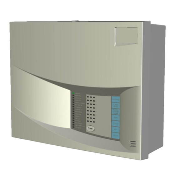
FireClass DUO-CEL Installation Manual
Fire detection/alarm control panel and repeater
Hide thumbs
Also See for DUO-CEL:
- Installation & commissioning manual (29 pages) ,
- Application manual (46 pages)

Related Manuals for FireClass DUO-CEL


Summary of Contents for FireClass DUO-CEL
- Page 1 DUO-CEL EQUIPMENT: WRITTEN BY: RKP OM_DUO-CEL_INST PUBLICATION: CHECKED BY: AJC 13/10/10 ISSUE No. & DATE: APPROVED BY: JBJ DUO-CEL Fire Detection/Alarm Control Panel and Repeater Installation and Commissioning Manual PAGE 1 of 30...
-
Page 2: Table Of Contents
....... 12 .... 5 INSTALLATION HECKS IGURE EMOTE ONTROL CONNECTIONS 4 – A 5.1.1 DUO-CEL Panel Installation Instructions ....5 IGURE LARM CIRCUIT CONFIGURATION 5 – T ......6 IGURE DEVICE 6 – S 5.1.2 Battery removal & Replacement ..... 14 ..... -
Page 3: Issue No. & Date
Quiescent: -5V DC [open circuit voltage] 2.1 Panel Identification Active [fire]: 24V The DUO-CEL panel & Repeater type can be [nominal] identified from the Part Number on the side of the enclosure (see section 14. for location details). DIODE 1N4002 The table below shows the part numbers. -
Page 4: Remote Control Input
DUO-CEL EQUIPMENT: WRITTEN BY: RKP OM_DUO-CEL_INST PUBLICATION: CHECKED BY: AJC 13/10/10 ISSUE No. & DATE: Panel Circuit Field Wiring 3.5.2 Alert The Alert function allows all sounder circuits to be operated in pulsing mode. Fire Relay When the Alert resistor is applied, the sounders will pulse until the resistor is removed. -
Page 5: Open Collector Outputs
DUO-CEL EQUIPMENT: WRITTEN BY: RKP OM_DUO-CEL_INST PUBLICATION: CHECKED BY: AJC ISSUE No. & DATE: 13/10/10 If the output is used to drive a relay then a 10k ¼ W EOL suppression diode should be used across the relay coil to avoid damaging the output driver circuit. -
Page 6: Standard Panel Default Zone Configuration
For the standard panel with 10uF EOL capacitor, head is removed. the maximum number of detectors & MCPs per zone is limited to 32 or less (see DUO-CEL 3.8.3 Twin-Wire Panel Zone Application Guide). Configuration... -
Page 7: Diagram
DUO-CEL EQUIPMENT: WRITTEN BY: RKP OM_DUO-CEL_INST PUBLICATION: CHECKED BY: AJC 13/10/10 ISSUE No. & DATE: 10uF 35V 6K8 to 3K9 (¼ 4W) end-of-line Capacitor end-of-line resistor Manual Call Point. ALERT: CP200, CP230, 1A 2A Manual Call Point. 1A 2A CP260... -
Page 8: Diagram
DUO-CEL EQUIPMENT: WRITTEN BY: RKP OM_DUO-CEL_INST PUBLICATION: CHECKED BY: AJC 13/10/10 ISSUE No. & DATE: 10K ¼ W EOL Resistor EOL Device. Zener & Resistor Polarised Electronic Sounder Sounder. Fulleon twin-wire sounder Polarised Electronic Sounder Manual Call Point. 1A 2A... -
Page 9: Panel To Repeater Wiring
EARTH BAR Data Cable EARTH STUD (Earth Bar may be present instead) Screen To Next Repeater AUX 0.25A REPEATER AUX 0.25A REPEATER 24V 0V 24V 0V DUO-CEL Panel DUO-CEL Repeater Figure 11 – Repeater Wiring Diagram PAGE 9 of 30... -
Page 10: Installation And Commissioning Procedure Overview
Procedure Overview WARNING: Read this section completely before commencing installation. This section lists the steps that are taken in installing and commissioning a DUO-CEL system. Reference should be made to the DUO-CEL Danger: This panel contains Application manual for technical details and power supply equipment which is description of panel features. - Page 11 DUO-CEL EQUIPMENT: WRITTEN BY: RKP OM_DUO-CEL_INST PUBLICATION: CHECKED BY: AJC 13/10/10 ISSUE No. & DATE: DANGER: incinerate IMPORTANT NOTES ON BATTERIES: batteries. If placed in a fire, the batteries may rupture, with the DANGER: Batteries are electrically potential to release hazardous gases live at all times, take great care never electrolyte.
-
Page 12: Pre-Installation Checks
Clamp panel) All items, except for the battery fuse, will be required for the installation of the panel. 5.1.1 DUO-CEL Panel Installation Instructions The front cover should have been removed as detailed above in the pre-installation checks. The front cover is not required during installation and commissioning, so leave it safely stored in the original packing box. - Page 13 DUO-CEL EQUIPMENT: WRITTEN BY: RKP OM_DUO-CEL_INST PUBLICATION: CHECKED BY: AJC 13/10/10 ISSUE No. & DATE: Insert the two 3.4Ah Powersonic batteries, positioning them with the spade terminals at the top. 10. Fix the battery clamp back into position to firmly hold the batteries.
-
Page 14: Battery Removal & Replacement
21. Ensure all 12 DIL switches on the panel are has been commissioned. See section 8.6. OFF. 5.1.2 Battery removal & Replacement Please refer to the DUO-CEL logbook for details on how and when to replace the standby batteries. PAGE 14 of 30... -
Page 15: Baq35T24 1.5A Power Connections
DUO-CEL EQUIPMENT: WRITTEN BY: RKP OM_DUO-CEL_INST PUBLICATION: CHECKED BY: AJC 13/10/10 ISSUE No. & DATE: Incoming Mains Cable Secured with a cable tie to the backbox Leave the Earth wire 3cm Earth Wire to longer than the EARTH bar Negative Live &... -
Page 16: Duo-Cel Repeater Installation Instructions
OM_DUO-CEL_INST PUBLICATION: CHECKED BY: AJC 13/10/10 ISSUE No. & DATE: 5.1.3 DUO-CEL Repeater Installation v) No end-of-line devices (e.g. alarm circuit EOL resistors) are fitted in the field. Instructions 2. The following information should be available The Repeater installation is generally the same as to the commissioning team: the panel installation. -
Page 17: Pre -Commissioning Wiring
DUO-CEL EQUIPMENT: WRITTEN BY: RKP OM_DUO-CEL_INST PUBLICATION: CHECKED BY: AJC 13/10/10 ISSUE No. & DATE: 6.4 Pre-Commissioning Wiring Check Final battery connections: Connect the blue battery lead across the NOTE: This pre-commissioning wiring check red & black battery terminals either side procedure should be followed to test all wiring of the battery clamp. -
Page 18: Panel Configuration
6.6.1 Basic Default Configuration dependency mode. If a fire condition occurs on a dependency zone, the When first powered up, the DUO-CEL panel can be panel will not immediately indicate the alarm. A operated in the factory default configuration: 30-minute counter will be started and the zone will ... -
Page 19: Repeater Configuration
DUO-CEL EQUIPMENT: WRITTEN BY: RKP OM_DUO-CEL_INST PUBLICATION: CHECKED BY: AJC 13/10/10 ISSUE No. & DATE: 7.2 Repeater Configuration 7.5 Resistor EOL The panel can be programmed to communicate with The Resistor EOL DIL switch configures all zones up to 3 repeaters. Repeaters can only be used with to monitor an end-of-line resistor (6K8 to 3K9) 4-zone &... -
Page 20: Selectable Zonal Or General
Standard panel, 1 to 4 zone panels: sounder fault indication clears. Sounder circuits 1 to 4 operate individually for a 3. Use the Alarm Test facility [see DUO-CEL fire condition on the respective zone. 1 and 2- User Manual] or press the Evacuate button to zone panels have 2 sounder circuits). -
Page 21: Zone Fire Indications
DUO-CEL EQUIPMENT: WRITTEN BY: RKP OM_DUO-CEL_INST PUBLICATION: CHECKED BY: AJC 13/10/10 ISSUE No. & DATE: 8.2.2 Zone Fire Indications Place a short circuit across the 10K EOL resistor and check that the panel indicates a On each zone in turn, start with the device Remote Control Fault. -
Page 22: Ancillary Outputs
DUO-CEL EQUIPMENT: WRITTEN BY: RKP OM_DUO-CEL_INST PUBLICATION: CHECKED BY: AJC 13/10/10 ISSUE No. & DATE: 8.5 Ancillary outputs 6. At the second repeater, only connect the wiring from the first repeater into the terminals on the Connect the field cabling into the Remote repeater. -
Page 23: Repeater Testing
DUO-CEL EQUIPMENT: WRITTEN BY: RKP OM_DUO-CEL_INST PUBLICATION: CHECKED BY: AJC 13/10/10 ISSUE No. & DATE: After a few seconds, the Communication Fault 8.7 Power Supply Unit. at the third repeater should clear and the panel 1. Ensure that the system is fully commissioned &... -
Page 24: System Handover
DUO-CEL EQUIPMENT: WRITTEN BY: RKP OM_DUO-CEL_INST PUBLICATION: CHECKED BY: AJC 13/10/10 ISSUE No. & DATE: 9. System Handover 10. System Maintenance Once the panel and repeaters have been installed System maintenance details can be found in the and fully tested in accordance with the site specific logbook. -
Page 25: User Indications
DUO-CEL EQUIPMENT: WRITTEN BY: RKP OM_DUO-CEL_INST PUBLICATION: CHECKED BY: AJC 13/10/10 ISSUE No. & DATE: 11. User Indications General Indicator Section Indicator Colour Operating Condition Supply On Green OFF: No mains or battery power, ON: Panel has power (battery and/or mains) -
Page 26: User Controls
DUO-CEL EQUIPMENT: WRITTEN BY: RKP OM_DUO-CEL_INST PUBLICATION: CHECKED BY: AJC 13/10/10 ISSUE No. & DATE: 12. User Controls SUPPLY ON EVACUATE GENERAL FIRE GENERAL FAULT GENERAL TEST SILENCE BUZZER GENERAL DISABLEMENT ALERT/EVAC ON SILENCE/ RESOUND FIRE SIGNAL ON ALARMS FIRE SIGNAL FLT / DIS / TST... -
Page 27: Pcb Layouts
WRITTEN BY: RKP OM_DUO-CEL_INST PUBLICATION: CHECKED BY: AJC 13/10/10 ISSUE No. & DATE: 13. PCB Layouts Figure 13 illustrates the control board for the DUO-CEL 8-zone panel with the PCB cover fitted. REMOTE CONTROL INPUT: REMOTE Class Change OUTPUTS: UNFUSED Alert ZONE INPUTS. -
Page 28: Cover
EQUIPMENT: WRITTEN BY: RKP OM_DUO-CEL_INST PUBLICATION: CHECKED BY: AJC 13/10/10 ISSUE No. & DATE: Figure 14 illustrates the control board for the DUO-CEL repeater with the PCB cover fitted. 24VDC RS485 INPUT NOTE: COMMS. For DC 24V & 0V Terminals are only... -
Page 29: General Assembly Drawing
DUO-CEL EQUIPMENT: WRITTEN BY: RKP OM_DUO-CEL_INST PUBLICATION: CHECKED BY: AJC 13/10/10 ISSUE No. & DATE: 14. General Assembly Drawing PAGE 29 of 30... -
Page 30: Alarm Count Display
DUO-CEL EQUIPMENT: WRITTEN BY: RKP OM_DUO-CEL_INST PUBLICATION: CHECKED BY: AJC 13/10/10 ISSUE No. & DATE: 15. Alarm Count Display NOTE: The Alarm Count Reset function is only accessible at access level 4, i.e. this function should The Alarm count can be displayed by pressing the only be operated by persons trained and authorized DISABLE button with the controls locked.
Need help?
Do you have a question about the DUO-CEL and is the answer not in the manual?
Questions and answers