FireClass DUO-CEL Application Manual
Fire detection/alarm panel
Hide thumbs
Also See for DUO-CEL:
- Installation manual (30 pages) ,
- Installation & commissioning manual (29 pages)
Table of Contents
Advertisement
Advertisement
Table of Contents

Related Manuals for FireClass DUO-CEL


Summary of Contents for FireClass DUO-CEL
- Page 1 FIRECLASS DUO-CEL EQUIPMENT: OM_FC_DUO-CEL_APP PUBLICATION: 20/06/18 ISSUE No. & DATE: © 2018 Johnson Controls. Tyco Fire & Security GmbH, Victor von Bruns-Strasse 21, 8212 Neuhausen am Rheinfall, Switzerland DUO-CEL FIRE DETECTION/ALARM PANEL Application Guide PAGE 1 of 46...
-
Page 2: Table Of Contents
11.7.3 Evacuate ..........28 ETECTION AND LARM ANEL ..........7 11.7.4 Silence Alarms ........28 ESCRIPTION 2.2.1 DUO-CEL control board ......7 11.7.5 Reset ..........28 2.2.2 Display overlay and insert ...... 7 11.8 O ..... 28 OLLECTOR UTPUTS 2.2.3 Power Supply ......... 8 11.8.1 Disabled Output ......... - Page 3 NCLOSURE EXTERNAL ABLE ANEL NPUT UPUT 2 – F ............5 VIEW ABLE LOAT HARGE OLTAGES FOR 2 – DUO-CEL 8 Z – VRLA ..... 13 IGURE ANEL EXPLODED OWERSONIC BATTERIES 3 – DUO-CEL P ............7 DIL S VIEW...
-
Page 4: Introduction
Enclosure construction: 2. General Description Three-part high quality moulded ABS plastic enclosure. The FIRECLASS DUO-CEL Panel range is fully Keyhole for access control key. compliant with the mandatory requirements and selected optional requirements of EN54 parts 2 and 14 knockouts for 20mm cable glands. -
Page 5: Panel Order Codes & Descriptions
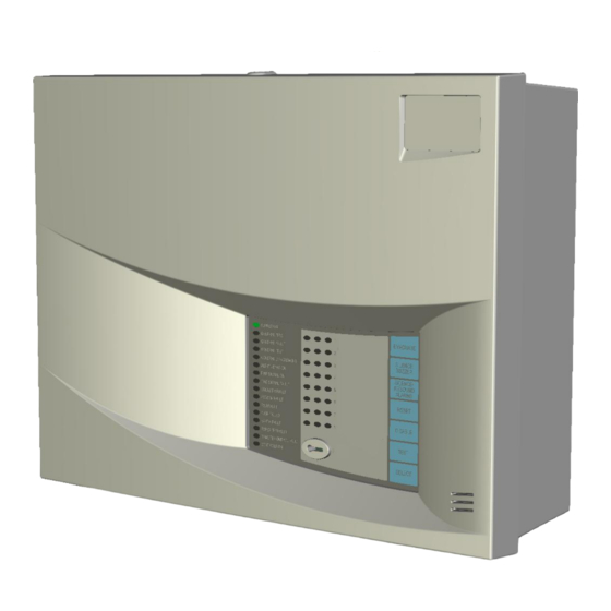
FIRECLASS DUO-CEL EQUIPMENT: OM_DUO-CEL_APP PUBLICATION: 20/06/18 ISSUE No. & DATE: Figure 1 – Panel/Repeater Enclosure external view SUPPLY ON EVACUATE GENERAL FIRE GENERAL FAULT GENERAL TEST SILENCE BUZZER GENERAL DISABLE ALERT / EVAC ON SILENCE / RESOUND FIRE SIGNAL ON... -
Page 6: Replacement Pcb Order Codes And Descriptions
FIRECLASS DUO-CEL EQUIPMENT: OM_DUO-CEL_APP PUBLICATION: 20/06/18 ISSUE No. & DATE: 2.1.2 Replacement PCB Order Codes and Descriptions CEL Part No Description Used in 2605501 1 Zone standard motherboard 508.031.701 2605502 2 Zone standard motherboard 508.031.702 2605503 4 Zone standard motherboard 508.031.703... -
Page 7: Duo-Cel Control Board
OM_DUO-CEL_APP PUBLICATION: 20/06/18 ISSUE No. & DATE: Fire Detection and Alarm Panel Description Figure 2 shows the exploded view of the DUO-CEL panel. Figure 2 – DUO-CEL 8 Zone Panel – exploded view Enclosure Backbox Mains Cable Restraint Earth Bar 3.4Ah... -
Page 8: Power Supply
FIRECLASS DUO-CEL EQUIPMENT: OM_DUO-CEL_APP PUBLICATION: 20/06/18 ISSUE No. & DATE: 2.2.3 Power Supply NOTE: The battery clamp is not designed to clamp batteries other than the PS-1230. The Power Supply is a self-contained switch-mode 2.2.4 Repeater Panel unit and is mounted underneath the control board. -
Page 9: Features List
FIRECLASS DUO-CEL EQUIPMENT: OM_DUO-CEL_APP PUBLICATION: 20/06/18 ISSUE No. & DATE: Features List Enclosure Injection moulded, 3-part, ABS plastic, flame retardant enclosure. Surface or Semi-flush mounting. 14 x 20mm Gland knockouts at the top. Temperature-compensated Battery charging voltage is automatically adjusted between 28.25Vdc and 26.72Vdc over an ambient temperature range of –5°C to +40°C. - Page 10 FIRECLASS DUO-CEL EQUIPMENT: OM_DUO-CEL_APP PUBLICATION: 20/06/18 ISSUE No. & DATE: Fire Signal Output Fully fault monitored output, providing 28VDC (nominal) at up to 250mA when active. Fire Relay Output Non- monitored Relay output, providing one set of volt-free change-over contacts.
-
Page 11: Duo-Cel Panel - Control
20/06/18 ISSUE No. & DATE: 4. DUO-CEL Panel – Control Board Features Figure 3 illustrates the control board for the 8 zone DUO-CEL panel with the PCB cover fitted. Figure 3 – Panel control board and PCB cover REMOTE CONTROL... -
Page 12: Duo-Cel Repeater - C
PUBLICATION: 20/06/18 ISSUE No. & DATE: 5. DUO-CEL Repeater – Control Board Features Figure 4 illustrates the control board for the DUO-CEL repeater with the PCB cover fitted. Figure 4 – Repeater control board and PCB cover 24VDC RS485 INPUT NOTE: COMMS. -
Page 13: Features
(a 15K resistor can be General used in place of the Thermistor to simulate 25 The DUO-CEL uses a BENTEL BAQ35T24 switch NOTES: mode Power Supply which has the following 1. The battery charging voltage is temperature... -
Page 14: Visual Indications
The yellow fault wire from the PSU is normally at 27Vdc (nominal). The panel monitors this signal 6.2.1 DUO-CEL Power Supply Features and indicates a PSU fault if the voltage is removed. and Connections Figure 5 shows the layout of the BAQ35T24 Power Supply. -
Page 15: Compatible Field Devices
FIRECLASS DUO-CEL EQUIPMENT: OM_DUO-CEL_APP PUBLICATION: ISSUE No. & DATE: 20/06/18 7. Compatible Field Devices The DUO-CEL panel is compatible with the devices listed in section 7.1. Field Device Part Numbers Max. Max. Devices Devices Standby Manufacturer Part no. Description Current... - Page 16 FIRECLASS DUO-CEL EQUIPMENT: OM_DUO-CEL_APP PUBLICATION: 20/06/18 ISSUE No. & DATE: Max. Max. Devices Devices Standby Manufacturer Part no. Description Current standard Twin-wire (mA) zone zone (10uF EOL) Apollo 55000-210 Series 60 integrating ion detector 0.035 NONE Apollo 55000-100 Series 60 Grade 1 heat detector 0.035...
- Page 17 FIRECLASS DUO-CEL EQUIPMENT: OM_DUO-CEL_APP PUBLICATION: 20/06/18 ISSUE No. & DATE: at low battery voltage and no mains power, e. All detector bases must have a 1N4002 on long cable runs. diode fitted across the line IN and line OUT terminals (usually on the positive line but b.
-
Page 18: Overview Of User Functions
FIRECLASS DUO-CEL EQUIPMENT: OM_DUO-CEL_APP PUBLICATION: 20/06/18 ISSUE No. & DATE: 8. Overview Of User Functions This section gives an overview of the functions available to the end user. User Indications General Indicator Section Indicator Colour Operating Condition Supply On Green... -
Page 19: User Controls
FIRECLASS DUO-CEL EQUIPMENT: OM_DUO-CEL_APP PUBLICATION: 20/06/18 ISSUE No. & DATE: User Controls SUPPLY ON EVACUATE GENERAL FIRE GENERAL FAULT GENERAL TEST SILENCE BUZZER GENERAL DISABLE ALERT / EVAC ON SILENCE / RESOUND FIRE SIGNAL ON ALARMS FIRE SIGNAL FAULT SNDR FLT / DIS / TEST... -
Page 20: Selection Of Zones Or
FIRECLASS DUO-CEL EQUIPMENT: OM_DUO-CEL_APP PUBLICATION: 20/06/18 ISSUE No. & DATE: Selection of Zones or Outputs for Disabled Zones and Outputs Disablement, Enablement or Test Any or all of the zones can be disabled. The panel provides a simple and straightforward... -
Page 21: Overview Of Engineersf
Operation of the SELECT button will then switch the Select cursor on, flashing at the zone 1 fault Engineer’s configuration process LED. On the DUO-CEL panel, most of the Engineer’s Pressing the Select button again will move the configuration facilities controlled flashing cursor to the next zone. -
Page 22: Zone 1 Non-Latch Operation
FIRECLASS DUO-CEL EQUIPMENT: OM_DUO-CEL_APP PUBLICATION: 20/06/18 ISSUE No. & DATE: status of the repeater configuration is also Twin Wire displayed on the Repeater Fault LEDs, which are The Twin Wire panels support Fulleon twin-wire visible when the front cover is removed. -
Page 23: Sounder Operation
Selectable Zonal or General Earth Fault monitoring. Alarm Sounder operation The DUO-CEL panel is designed to monitor for low impedance faults to earth on the field cables. Earth The Zonal Alarms DIL switch allows the sounder faults can lead to false alarms or failure to operate circuits to operate zonally in line with the zone in the sounders or other outputs. -
Page 24: Repeater Useri
FIRECLASS DUO-CEL EQUIPMENT: OM_DUO-CEL_APP PUBLICATION: 20/06/18 ISSUE No. & DATE: 10.1 Repeater User Indications General Indicator Section Indicator Colour Operating Condition Supply On Green OFF: No mains or battery power, ON: Panel has power (battery and/or mains) OFF: Quiescent, FLASH: New Alarm Condition, ON: Alarm Accepted... -
Page 25: Ontrols
FIRECLASS DUO-CEL EQUIPMENT: OM_DUO-CEL_APP PUBLICATION: 20/06/18 ISSUE No. & DATE: 10.2 Repeater User Controls SUPPLY ON EVACUATE GENERAL FIRE GENERAL FAULT GENERAL TEST SILENCE BUZZER GENERAL DISABLE ALERT / EVAC ON SILENCE / RESOUND FIRE SIGNAL ON ALARMS FIRE SIGNAL FAULT... -
Page 26: Repeater Userc
ISSUE No. & DATE: 11. Circuit Connection Details 11.1 DUO-CEL Panel Motherboard Termination Details Figure 6 below shows the available field wiring terminals for the DUO-CEL Panel. Figure 6 – DUO-CEL Panel field terminations 1 ZONE 1 ZONE 2 ZONE... -
Page 27: Duo-Cel Repeater Termination Details
Field Wiring Panel Terminals Figure 7 below shows the available field wiring DIODE terminals for the DC powered DUO-CEL Repeater. 1N4002 The mains AC powered repeater does not have the two sets of terminals marked 24V & 0V. Output conditions: Figure 7 –... -
Page 28: Remote Control Input
FIRECLASS DUO-CEL EQUIPMENT: OM_DUO-CEL_APP PUBLICATION: 20/06/18 ISSUE No. & DATE: 11.7 Remote Control Input faults to be cleared, returning the panel to the quiescent state. The Auxiliary 24VDC supply may A single 2-terminal input allows remote operation of also be switched off for 10 seconds if configured to the following functions: do so. -
Page 29: Disabled Output
11.10.2 Standard Panel Resistor Zone Configuration 11.9 Sounder Circuits The DUO-CEL panel has up to 4 standard sounder The standard panel can be set to resistor zone circuits, each rated at 0.5 Amps (not including twin- configuration (set by DIL switch). This uses passive wire sounders). -
Page 30: Maximum Number Of Detectors/Mcps On A Zone
FIRECLASS DUO-CEL EQUIPMENT: OM_DUO-CEL_APP PUBLICATION: 20/06/18 ISSUE No. & DATE: Figure 12 – Twin-Wire EOL device Figure 13 – Standard Zone Wiring Diagram Zener Diode 10uF 35V 17V 5W end-of-line Capacitor Manual Call Point. ALERT: Resistor CP200, CP230, 1A 2A... -
Page 31: Figure 14 - Resistor Eol Zone
FIRECLASS DUO-CEL EQUIPMENT: OM_DUO-CEL_APP PUBLICATION: 20/06/18 ISSUE No. & DATE: Figure 14 – Resistor EOL Zone Wiring Figure 15 – Twin-Wire Zone Wiring Diagram Diagram 6K8 to 3K9 (¼ W) end-of-line resistor EOL Device. Zener & Resistor Manual Call Point. -
Page 32: Figure 16 - Alarm Circuitw
FIRECLASS DUO-CEL EQUIPMENT: OM_DUO-CEL_APP PUBLICATION: 20/06/18 ISSUE No. & DATE: Figure 16 – Alarm Circuit Wiring Diagram Figure 17 – Remote Indicators Wiring Diagram 10K ¼ W EOL Resistor Current Limiting Resistors 590R Polarised Electronic 1.5W Sounder minimum 24Vdc Buzzer,... -
Page 33: Panel To Repeaterw
FIRECLASS DUO-CEL EQUIPMENT: OM_DUO-CEL_APP PUBLICATION: ISSUE No. & DATE: 20/06/18 11.11 Panel to Repeater Wiring If the cable includes a screen then this should be earthed at the panel & all repeaters. The Repeater RS485 communication and 24Vdc power connections should all be made via a single Terminal A at the panel must be connected to multi-core data cable. -
Page 34: Mechanical & Electricals
FIRECLASS DUO-CEL EQUIPMENT: OM_DUO-CEL_APP PUBLICATION: 20/06/18 ISSUE No. & DATE: 12. Mechanical & Electrical Specification Mechanical Specification Panel Repeater c/w PSU Size (mm) HxWxD 273 x 365 x 110 273 x 365 x 110 Weight excluding batteries (kg) Bentel Power Supply Specification... -
Page 35: Environmental Specification
FIRECLASS DUO-CEL EQUIPMENT: OM_DUO-CEL_APP PUBLICATION: 20/06/18 ISSUE No. & DATE: 13. Environmental Specification Environmental Specification Ingress Protection IP 30 Rating Panel operating ambient C to +40 temperature range Storage temperature C to + 70 range Operating and storage 95% Non condensing... -
Page 36: Duo-Cel Input And Output
EQUIPMENT: OM_DUO-CEL_APP PUBLICATION: 20/06/18 ISSUE No. & DATE: 14. DUO-CEL Input and Output Specification Detection Zone Inputs Active open circuit & Head Removal monitoring, with optional conventional open circuit fault monitoring. Conventional short circuit fault monitoring. Conventional Fire Alarm monitoring with optional Detector/MCP discrimination. - Page 37 FIRECLASS DUO-CEL EQUIPMENT: OM_DUO-CEL_APP PUBLICATION: 20/06/18 ISSUE No. & DATE: Outputs Evacuate Activated Open collector. 50mA 30V maximum current sink Buzzer Activated Open collector. 50mA 30V maximum current sink Disabled Open collector. 50mA 30V maximum current sink Fire Signal Output Quiescent: -2.6Vdc (10k EOL present, reverse polarity monitored)
- Page 38 FIRECLASS DUO-CEL EQUIPMENT: OM_DUO-CEL_APP PUBLICATION: 20/06/18 ISSUE No. & DATE: Auxiliary Supply Maximum Current 0.25 [Amps] Auxiliary supply 27 – 20 (dependent on battery condition) (battery operation) [Volts DC] Auxiliary supply 28.4 – 26.4 (dependent on temperature) (mains operation) [Volts DC]...
-
Page 39: Appendix
Auxiliary 24Vdc supply reset to interrupt Clause 7.3 Indication of the zones in power to external equipment that needs to alarm. be reset in tandem with the DUO-CEL Clause 7.4 Audible indication (of fire panel (e.g. IR Beam Detectors). ... -
Page 40: Power Supply Loadc
FIRECLASS DUO-CEL EQUIPMENT: OM_DUO-CEL_APP PUBLICATION: 20/06/18 ISSUE No. & DATE: 15.5 Power Supply Load Calculation The power supply load must not exceed 1.5 Amps. To determine the maximum power supply load perform the following steps: 1. Look-up the mains failed panel load in alarm. Enter this value as panel 2. - Page 41 A battery Calculation worksheet is included on the next page. Notes: The DUO-CEL panel is designed to house and charge POWERSONIC 3.4Ah batteries to 80% capacity in 24 hours. Any batteries that cannot be accommodated within the DUO-CEL enclosure must be located in an enclosure adjacent to the DUO-CEL.
-
Page 42: Standby Battery Capacity Calculation Worksheet
Equipment Quantity Current Failed (each) Current (each) Current (mA) (mA) (mA) DUO-CEL Panel type 1 Zone Panel 2 Zone Panel 4 Zone Panel 8 Zone Panel Optional equipment connected to 24Vdc outputs Repeater 2-Wire Sounders on zones Symphoni 0.05 Squashni 0.05... -
Page 43: A1466 Interface Relay
This relay is compatible with the Fire Signal Output output. The 10K EOL resistor should be connected on the DUO-CEL panel. It provides two sets of volt- across the 24V & 0V terminals of the A1466 board.. free normally open & normally closed contacts. -
Page 44: Esign Chart
FIRECLASS DUO-CEL EQUIPMENT: OM_DUO-CEL_APP PUBLICATION: 20/06/18 ISSUE No. & DATE: 15.8 Panel Configuration Design Chart Table 3 – DUO-CEL Panel DIL Switch Configuration Design/Record Switc Actual Function Position Setting Zone 1 Latching Fire Alarm Indication Zone 1 Non-latching Fire Alarm Indication... - Page 45 FIRECLASS DUO-CEL EQUIPMENT: OM_DUO-CEL_APP PUBLICATION: 20/06/18 ISSUE No. & DATE: 16. General Assembly Drawing PAGE 45 of 46...
- Page 46 FIRECLASS DUO-CEL EQUIPMENT: OM_DUO-CEL_APP PUBLICATION: 20/06/18 ISSUE No. & DATE: PAGE 46 of 46 © 2018 Johnson Controls. Tyco Fire & Security GmbH, Victor von Bruns-Strasse 21, 8212 Neuhausen am Rheinfall, Switzerland...
Need help?
Do you have a question about the DUO-CEL and is the answer not in the manual?
Questions and answers