Sign In
Upload
Manuals
Brands
FireClass Manuals
Smoke Alarm
DUO-CEL
FireClass DUO-CEL Manuals
Manuals and User Guides for FireClass DUO-CEL. We have
3
FireClass DUO-CEL manuals available for free PDF download: Application Manual, Installation Manual, Installation & Commissioning Manual
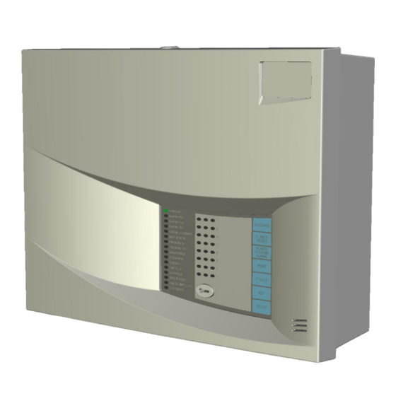
FireClass DUO-CEL Application Manual (46 pages)
FIRE DETECTION/ALARM PANEL
Brand:
FireClass
| Category:
Fire Alarms
| Size: 1.4 MB
Table of Contents
Table of Contents
2
Introduction
4
General Description
4
Cabinet Specifications
4
Panel Order Codes & Descriptions
5
Figure 1 - Panel /Repeatere
5
Replacement PCB Order Codes and Descriptions
6
Optional Language Display Overlays
6
Description
6
DUO-CEL Control Board
7
Display Overlay and Insert
7
Duo-Cel 8 Zone
7
Power Supply
8
Repeater Panel
8
Functional Specification
8
Panel Input /Output
8
List
8
Features List
9
Duo-Cel Panel - Control
11
Figure 3 - Panel Control Board and
11
Duo-Cel Repeater - C
12
Figure 4 - Repeater Control Board and
12
Features
13
Power Supply
13
General
13
Supply Input
13
Supply Output
13
Battery Charger
13
Battery Monitoring
13
Powersonic Vrla
13
Visual Indications
14
Fault Conditions
14
Mechanical Protection
14
DUO-CEL Power Supply Features and Connections
14
Baq35T24 1.5A P
14
Compatible Field Devices
15
Field Device Partn
15
Umbers
15
Overview of User Functions
18
User Indications
18
User Controls
19
Selection of Zones or
20
Disabled Zones and 8.5 Detector Zone Test
20
Alarm Soundero
20
Ne man Test
20
Overview of Engineersf
21
Zone Dependency Selection
21
Repeater Configuration
21
Unctions
21
S Configuration Process
21
Zone 1 Non-Latch Operation
22
Twin Wire
22
Alert Mode
22
Eol
22
Sounder Operation
23
Buzzer Disable
23
Earth Fault Monitoring
23
Panel Repeaters
23
Repeater Useri
24
Ndications
24
Ontrols
25
Repeater Userc
26
Circuit Connection Details
26
Duo-Cel Panel M Termination Details
26
Outputs for
26
Outputs
26
Duo-Cel Repeater Termination Details
27
Auxiliary Supply
27
Fire Signal Output
27
Fire Relay Output
27
Fault Relay Output
27
Duo-Cel R
27
Figure 8 - Fire Signal Output
27
Figure 9 - Relay Contact Connection Details
27
Remote Control Input
28
Class Change
28
Alert
28
Evacuate
28
Silence Alarms
28
Reset
28
Open Collector Outputs
28
Figure 10 - Remote Control
28
Disabled Output
29
Evacuate Output
29
Buzzer Active Output
29
Sounder Circuits
29
Standard Panel Default Zone Configuration
29
Standard Panel Resistor Zone Configuration
29
Twin-Wire Panel
29
Figure 11 - Alarm Circuit Configuration
29
Maximum Number of Detectors/Mcps on a Zone
30
Figure 12 - Twin -Wire Eol
30
Figure 13 - Standard Zonew
30
Figure 14 - Resistor Eol Zone
31
Figure 15 - Twin -Wire Zonew
31
Figure 16 - Alarm Circuitw
32
Figure 17 - Remote Indicators
32
Panel to Repeaterw
33
Iring
33
Figure 18 - Repeater Wiring
33
Mechanical & Electricals
34
Pecification
34
Environmental Specification
35
Duo-Cel Input and Output
36
Specification
36
Appendix
39
En54 Mandatoryf
39
En54 Optional Functions
39
Requirements
39
Ancillary Functionsn
39
En54
39
Safe State
39
Unctions
39
Power Supply Loadc
40
Minimum Standby Battery Calculation
40
Alculation
40
Standby Battery Capacity Calculation Worksheet
42
A1466 Interface Relay
43
A1466 Interface
43
Esign Chart
44
Duo-Cel P
44
Advertisement
FireClass DUO-CEL Installation & Commissioning Manual (29 pages)
Brand:
FireClass
| Category:
Smoke Alarm
| Size: 1.07 MB
Table of Contents
Table of Contents
2
1 Introduction
3
Panel Identification
3
2 Panel Circuit Details
3
Auxiliary Supply
3
Fire Signal Output
3
Fire Relay Output
3
Fault Relay Output
3
Onnections
3
Remote Control Input
4
Class Change
4
Alert
4
Evacuate
4
Silence Alarms
4
Reset
4
Open Collector Outputs
5
Disabled Output
5
Evacuate Output
5
Buzzer Active Output
5
Sounder Circuits
5
Standard Panel Default Zone Configuration
5
Etection Zones
5
Connections
5
Standard Panel Resistor Zone Configuration
6
Twin-Wire Panel Zone Configuration
6
Maximum Number of Devices on a Zone
6
Diagram
6
Iring Diagram
7
Diagram
7
PUBLICATION: ISSUE No. & DATE
8
Diagram
8
Figure 9 – Alarm Circuit Wiring Diagram
8
Wiring Diagram . 8 Iagram
9
Panel to Repeater Wiring
10
3 Installation and Commissioning
10
Overview
10
4 Installation
10
Electrical Safety
10
Pre-Installation Checks
12
DUO-CEL Panel Installation
12
Instructions
12
Battery Removal & Replacement
14
Baq35T24 1.5A P Connections
15
DUO-CEL Repeater Installation
16
Instructions
16
5 Panel Commissioning
16
Introduction
16
Commissioning Checklist
16
A Noverview of Thec
16
Procedure
16
Pre -Commissioningw
16
Iring Check
16
Powering up
17
Panel Configuration
17
Basic Default Configuration
17
Site-Specific Configuration
17
6 Operating the Engineer's Functions
18
Zone Dependency Selection
18
Repeater Configuration
18
Repeater Selection
18
Invalid Configuration Conditions
18
Coincidence )
18
Zone 1 Non-Latch Operation
19
Alert Mode
19
Selectable Zonal Org
19
Sounder Operation
19
Eol
19
Buzzer Disable
19
Earth Fault Monitoring
19
7 Ommissioning the Panel
20
General Alarm Circuits
20
Detection Zones
20
Zone Fault Indications
20
Zone Fire Indications
20
Remote Control Input
20
Fire Signal Output
21
Ancillary Outputs
21
Repeaters
21
Repeater Testing
22
Power Supply Unit
22
Final Dressing of Thec
22
Ables
22
Site Configuration
23
8 Ystem Handover
23
9 Ystem Maintenance
23
10 User Indications
24
11 User Controls
25
12 Pcb Layouts
26
Igure 13 - Panel Control Board and
26
Pcb Cover
26
Cover
27
G Eneral a Ssembly D Rawing
28
13 General Assembly Drawing 14. Alarm Count Display
29
14 Alarm Count Display
29
Assignment
29
FireClass DUO-CEL Installation Manual (30 pages)
Fire Detection/Alarm Control Panel and Repeater
Brand:
FireClass
| Category:
Control Panel
| Size: 1.35 MB
Table of Contents
1 List of Figures
2
Table of Contents
2
2 Introduction
3
Panel Identification
3
ISSUE No. & DATE
3
3 Panel Circuit Details
3
Auxiliary Supply
3
Fire Signal Output
3
Fire Relay Output
3
Fault Relay Output
3
Onnections
3
Remote Control Input
4
Class Change
4
Alert
4
Evacuate
4
Silence Alarms
4
Reset
4
Open Collector Outputs
5
Disabled Output
5
Evacuate Output
5
Buzzer Active Output
5
Sounder Circuits
5
Etection Zones
5
Connections
5
Standard Panel Default Zone Configuration
6
Standard Panel Resistor Zone Configuration
6
Twin-Wire Panel Zone Configuration
6
Maximum Number of Devices on a Zone
6
Igure 4 - Alarm Circuit Configuration Igure 5 - Twin -Wire Eol Device
6
Diagram
7
Iring Diagram
7
Diagram
8
Panel to Repeater Wiring
9
Iring Diagram
9
Iagram
9
4 Installation and Commissioning Procedure Overview
10
Baq35T24 1.5A Power Connections
15
DUO-CEL Repeater Installation Instructions
16
5 Installation
10
Electrical Safety
10
Pre-Installation Checks
12
DUO-CEL Panel Installation Instructions
12
Battery Removal & Replacement
14
6 Panel Commissioning
16
Introduction
16
Commissioning Checklist
16
A Noverview of Thec
16
Procedure
16
Pre -Commissioning Wiring
17
Powering up
17
Check
17
Panel Configuration
18
Basic Default Configuration
18
Site-Specific Configuration
18
7 Operating the Engineer's Functions
18
Zone Dependency Selection
18
Coincidence )
18
Repeater Configuration
19
Repeater Selection
19
Invalid Configuration Conditions
19
Zone 1 Non-Latch Operation
19
Resistor Eol
19
Alert Mode
19
Selectable Zonal or General
20
Sounder Operation
20
Buzzer Disable
20
Earth Fault Monitoring
20
8 Commissioning the Panel
20
General Alarm Circuits
20
Detection Zones
20
Zone Fault Indications
20
Zone Fire Indications
21
Remote Control Input
21
Fire Signal Output
21
Ancillary Outputs
22
Repeaters
22
Repeater Testing
23
Power Supply Unit
23
Final Dressing of the Cables
23
Site Configuration
23
9 System Handover
24
10 System Maintenance
24
11 User Indications
25
12 User Controls
26
13 Pcb Layouts
27
Pcb Cover
27
Cover
28
14 General Assembly Drawing
29
15 Alarm Count Display
30
Assignment
30
Advertisement
Advertisement
Related Products
FireClass FIRERAY 100
FireClass FIRERAY 50
FireClass Prescient III
FireClass Categories
Control Panel
Fire Alarms
I/O Systems
Control Unit
Smoke Alarm
More FireClass Manuals
Login
Sign In
OR
Sign in with Facebook
Sign in with Google
Upload manual
Upload from disk
Upload from URL