Table of Contents
Advertisement
Quick Links
INSTALLATION AND OPERATION MANUAL
CWGE28FX4TX24MS
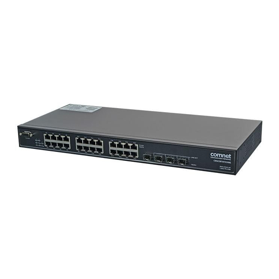
(24) 10/100/1000 BASE-TX + (4) 1000BASE-FX
MANAGED ETHERNET SWITCH
The ComNet
CWGE28FX4TX24MS Layer 2 Managed 28 Port Ethernet Switch supports
™
twenty-four (24) 10/100/1000BASE-TX ports and four (4) 1000BASE-FX ports of Ethernet
data. The four 1000BASE-FX ports are SFP configurable for fiber type (multimode or
single-mode), connector type and distance. The exclusive C-Ring redundant ring
feature protects networks from interruptions or temporary malfunctions with its fast
recovery technology. The electrical ports support the 10/100/1000 Mbps Ethernet IEEE
802.3 protocol, and auto-negotiating and auto-MDI/MDIX features are included. The
CWGE28FX4TX24MS are optically (1000BASE-FX) and electrically compatible with any
IEEE 802.3 compliant Ethernet device.
Advertisement
Table of Contents

Related Manuals for Comnet CWGE28FX4TX24MS


Summary of Contents for Comnet CWGE28FX4TX24MS
- Page 1 (24) 10/100/1000 BASE-TX + (4) 1000BASE-FX MANAGED ETHERNET SWITCH The ComNet CWGE28FX4TX24MS Layer 2 Managed 28 Port Ethernet Switch supports ™ twenty-four (24) 10/100/1000BASE-TX ports and four (4) 1000BASE-FX ports of Ethernet data. The four 1000BASE-FX ports are SFP configurable for fiber type (multimode or single-mode), connector type and distance.
-
Page 2: Table Of Contents
INSTALLATION AND OPERATION MANUAL CWGE28FX4TX24MS Contents About This Guide Related Documentation About ComNet Website Support Safety Overview Introduction Software Features Hardware Features Hardware Installation Rear Panel Rack mount kit assembly Cables Ethernet Cables SFP (Small Form-Factor Pluggable) Optical Connectors Console Cable... -
Page 3: About This Guide
» CWGE28FX4TX24MS Datasheet About ComNet ComNet develops and markets the next generation of video solutions for the CCTV, defense, and homeland security markets. At the core of ComNet’s solutions are a variety of high-end video servers and the ComNet IVS software, which provide the industry with a standard platform for analytics and security management systems enabling leading performance, compact and cost effective solutions. -
Page 4: Overview
Moreover, the ComNet CWGE28FX4TX24MS switch provides advanced DoS/DDoS auto prevention. If an IP flow rises quickly, the CWGE28FX4TX24MS switch will lock the source IP address for a certain time to prevent the attack. It is hardware-based prevention so it can prevent DDOS attack immediately and completely. -
Page 5: Software Features
INSTALLATION AND OPERATION MANUAL CWGE28FX4TX24MS Software Features » Industry’s fastest Redundant Ethernet Ring (Gigabit model recovery time < 30ms over 250 units connection) » Support for Ring Coupling, Dual Homing over Ring and standard STP/RSTP » Support for SNMPv1/v2c/v3 & RMON & Port base/802.1Q VLAN Network Management »... -
Page 6: Hardware Features
INSTALLATION AND OPERATION MANUAL CWGE28FX4TX24MS Hardware Features » One 100~240VAC power input » Operating Temperature: -10˚ to +60˚ C (+14˚ to +140˚ F) » Storage Temperature: -40 to 85ºC (-40 to 185ºF) » Operating Humidity: 5% to 95%, non-condensing » Casing: IP-20 »... -
Page 7: Hardware Installation
INSTALLATION AND OPERATION MANUAL CWGE28FX4TX24MS Hardware Installation CWGE28FX4TX24MS Front Panel The following table describes the labels that are on the CWGE28FX4TX24MS switch Port Description Gigabit SFP ports 4 × 1000Base-X on SFP port Gigabit Ethernet Port 24 × 10/100/1000Base–T(X) Console Use RS-232 with DB9 connecter to manage switch. -
Page 8: Rear Panel
INSTALLATION AND OPERATION MANUAL CWGE28FX4TX24MS Rear Panel CWGE28FX4TX24MS Rear Panel 1. Power Switch 2. Power input for AC 100V~240V / 50~60Hz Rack mount kit assembly You can find the rack mount kit and the screws in the packing box. Please assembly the rack mount kit on the switch with screws as shown below: TECH SUPPORT: 1.888.678.9427... - Page 9 INSTALLATION AND OPERATION MANUAL CWGE28FX4TX24MS Front Panel LEDs Color Status Description Green DC power module activated. Power module is in PWR UP state Green Blinking The system is upgrading firmware Green System resets to default configuration. Green Slowly blinking System is operating continuously.
-
Page 10: Cables
Cables Ethernet Cables The CWGE28FX4TX24MS series switches have standard Ethernet ports. According to the link type, the switches use CAT 3, 4, 5,5e UTP cables to connect to any other network device (PCs, servers, switches, routers, or hubs). Please refer to the following table for cable specifications. - Page 11 Note: “+” and “-” signs represent the polarity of the wires that make up each wire pair. The CWGE28FX4TX24MS switch support auto MDI/MDI-X operation. You can use a straight- through cable to connect a PC to the switch. The following table below shows the 10BASE-T/ 100BASE-TX MDI and MDI-X port pin outs.
-
Page 12: Sfp (Small Form-Factor Pluggable) Optical Connectors
Note: “+” and “-” signs represent the polarity of the wires that make up each wire pair. SFP (Small Form-Factor Pluggable) Optical Connectors The Switch has fiber optic ports for use with with SFP connectors. There are many ComNet SFP modules available with either multimode or single-mode fiber, connector type and distance available. -
Page 13: Console Cable
CWGE28FX4TX24MS Console Cable CWGE28FX4TX24MS switch can be managed through the console port. The DB-9 to RJ-45 cable can be found in the package. You can connect them to PC via a RS-232 cable with DB-9 female connector and the other end (RJ-45 connector) connects to console port of switch. -
Page 14: Web Management
INSTALLATION AND OPERATION MANUAL CWGE28FX4TX24MS WEB Management Attention: While installing and upgrading firmware, please remove physical loop connection first. DO NOT power off equipment while the firmware is upgrading! Configuration by Web Browser This section introduces the configuration by Web browser. -
Page 15: Main Interface
INSTALLATION AND OPERATION MANUAL CWGE28FX4TX24MS 5. Click “Enter” or ”OK” button, then the main interface of the Web-based management appears. Login screen Main Interface Main interface TECH SUPPORT: 1.888.678.9427 INS_CWGE28FX4TX24MS_REV– 08/31/12 PAGE 15... - Page 16 INSTALLATION AND OPERATION MANUAL CWGE28FX4TX24MS Basic Setting System Information The switch system information is provided here. System Information interface Label Description System Contact The textual identification of the contact person for this managed node, together with information on how to contact this person. The allowed string length is 0 to 255, and the allowed content is the ASCII characters from 32 to 126.
- Page 17 INSTALLATION AND OPERATION MANUAL CWGE28FX4TX24MS Admin Password This page allows you to configure the system password required to access the web pages or log in from CLI. Label Description Old Password Enter the current system password. If this is incorrect, the new password will not be set.
- Page 18 INSTALLATION AND OPERATION MANUAL CWGE28FX4TX24MS IP Setting Configure the switch-managed IP information on this page. Label Description DHCP Client Enable the DHCP client by checking this box. If DHCP fails and the configured IP address is zero, DHCP will retry. If DHCP fails and the configured IP address is non-zero, DHCP will stop and the configured IP settings will be used.
- Page 19 INSTALLATION AND OPERATION MANUAL CWGE28FX4TX24MS HTTPS Label Description Mode Indicates the HTTPS mode operation. Possible modes are: Enabled: Enable HTTPS mode operation. Disabled: Disable HTTPS mode operation. Save Click to save changes. Reset Click to undo any changes made locally and revert to previously saved values.
- Page 20 INSTALLATION AND OPERATION MANUAL CWGE28FX4TX24MS LLDP LLDP Configuration This page allows the user to inspect and configure the current LLDP port settings. Label Description Port The switch port number of the logical LLDP port. Mode Select LLDP mode. Rx only The switch will not send out LLDP information, but LLDP information from neighbor units is analyzed.
- Page 21 INSTALLATION AND OPERATION MANUAL CWGE28FX4TX24MS LLDP Neighbor Information This page provides a status overview for all LLDP neighbors. The displayed table contains a row for each port on which an LLDP neighbor is detected. The columns hold the following information:...
- Page 22 INSTALLATION AND OPERATION MANUAL CWGE28FX4TX24MS LLDP Statistics This page provides an overview of all LLDP traffic. Two types of counters are shown. Global counters are counters that refer to the whole stack, switch, while local counters refer to counters for the currently selected switch.
- Page 23 INSTALLATION AND OPERATION MANUAL CWGE28FX4TX24MS Local Counters Label Description Local Port The port on which LLDP frames are received or transmitted. Tx Frames The number of LLDP frames transmitted on the port. Rx Frames The number of LLDP frames received on the port.
- Page 24 INSTALLATION AND OPERATION MANUAL CWGE28FX4TX24MS Backup/Restore Configuration You can save/view or load the switch configuration. The configuration file is in XML format with a hierarchy of tags: Firmware Update This page facilitates an update of the firmware controlling the switch.
- Page 25 INSTALLATION AND OPERATION MANUAL CWGE28FX4TX24MS DHCP Server Setting The system supports DHCP server function. Enable the DHCP server function and the switch system will become a DHCP server. DHCP Dynamic Client List When the DHCP server function is activated, the system will collect the DHCP client information and display in here.
- Page 26 INSTALLATION AND OPERATION MANUAL CWGE28FX4TX24MS DHCP Client List You can assign a specific IP address that is in the assigned dynamic IP range to the specific port. When the device is connecting to the port and asks for dynamic IP address assignment, the system will assign the IP address that has been assigned before in the connected device.
- Page 27 INSTALLATION AND OPERATION MANUAL CWGE28FX4TX24MS Port Setting Port Control This page displays the current port configurations. Ports can also be configured here. Label Description Port This is the logical port number for this row. Link The current link state is displayed graphically. Green indicates the link is up and red that it is down.
- Page 28 INSTALLATION AND OPERATION MANUAL CWGE28FX4TX24MS Power Control The Usage column shows the current percentage of the power consumption per port. The Configured column allows for changing the power savings mode parameters per port. Disabled: All power savings mechanisms disabled. ActiPHY: Link down power savings enabled.
- Page 29 INSTALLATION AND OPERATION MANUAL CWGE28FX4TX24MS Rate Limit Configure the switch port rate limit for traffic policing and shaping on this page. Label Description Port The logical port for the settings contained in the same row. Traffic policing Enable or disable the port traffic policing. The default value is “Disabled”.
- Page 30 INSTALLATION AND OPERATION MANUAL CWGE28FX4TX24MS Port Trunk Trunk Configuration This page is used to configure the Aggregation hash mode and the aggregation group. Label Description Source MAC The Source MAC address can be used to calculate the destination port for the frame.
- Page 31 INSTALLATION AND OPERATION MANUAL CWGE28FX4TX24MS Label Description Group ID Indicates the group ID for the settings contained in the same row. Group ID “Normal” indicates there is no aggregation. Only one group ID is valid per port. Port Members Each switch port is listed for each group ID. Select a radio button to include a port in an aggregation, or clear the radio button to remove the port from the aggregation.
- Page 32 INSTALLATION AND OPERATION MANUAL CWGE28FX4TX24MS LACP Port Configuration This page allows the user to inspect the current LACP port configurations, and change as required. Label Description Port Indicates the group ID for the settings contained in the same row. Group ID “Normal”...
- Page 33 INSTALLATION AND OPERATION MANUAL CWGE28FX4TX24MS LACP System Status This page provides a status overview for all LACP instances. Label Description Aggr ID The Aggregation ID associated with this aggregation instance. For LLAG the id is shown as ‘isid:aggr-id’ and for GLAGs as ‘aggr-id’...
- Page 34 INSTALLATION AND OPERATION MANUAL CWGE28FX4TX24MS LACP Status This page provides a status overview for LACP status for all ports. Label Description Port The switch port number. LACP ‘Yes’ means that LACP is enabled and the port link is up. ‘No’ means that LACP is not enabled or that the port link is down.
- Page 35 INSTALLATION AND OPERATION MANUAL CWGE28FX4TX24MS Label Description Port The switch port number LACP Transmitted Shows how many LACP frames have been sent from each port LACP Received Shows how many LACP frames have been received at each port. Discarded Shows how many unknown or illegal LACP frames have been discarded at each port.
- Page 36 INSTALLATION AND OPERATION MANUAL CWGE28FX4TX24MS Redundancy C-Ring C-Ring is the most powerful Redundant Ring in the world. The recovery time of C-Ring is less than 30 ms. It can reduce unexpected damage caused by network topology change. C-Ring Supports 3 Ring topology: C-Ring, Coupling Ring and Dual Homing.
- Page 37 INSTALLATION AND OPERATION MANUAL CWGE28FX4TX24MS Legacy Ring Legacy ring provides support for the switch to be used in an existing ring of ComNet X-Ring enabled switches. X-Ring provides a faster redundant recovery than Spanning Tree topology. The action is similar to STP or RSTP, but the algorithms between them are not the same.
- Page 38 INSTALLATION AND OPERATION MANUAL CWGE28FX4TX24MS MSTP Bridge Settings This page allows you to configure RSTP system settings. The settings are used by all RSTP Bridge instances in the Switch Stack. Label Description Protocol Version The STP protocol version setting. Valid values are STP, RSTP and MSTP.
- Page 39 INSTALLATION AND OPERATION MANUAL CWGE28FX4TX24MS MSTI Mapping This page allows the user to inspect the current STP MSTI bridge instance priority configurations, and possibly change them as well. Label Description Configuration The name identifying the VLAN to MSTI mapping. Bridges must share the name and...
- Page 40 INSTALLATION AND OPERATION MANUAL CWGE28FX4TX24MS MSTI Priorities This page allows the user to inspect the current STP MSTI bridge instance priority configurations, and possibly change them as well. Label Description MSTI The bridge instance. The CIST is the default instance, which is always active.
- Page 41 INSTALLATION AND OPERATION MANUAL CWGE28FX4TX24MS CIST Ports This page allows the user to inspect the current STP CIST port configurations, and possibly change them as needed. This page contains settings for physical and aggregated ports. The aggregation settings are stack global.
- Page 42 INSTALLATION AND OPERATION MANUAL CWGE28FX4TX24MS Label Description Port The switch port number of the logical STP port. STP Enabled Controls whether STP is enabled on this switch port. Path Cost Controls the path cost incurred by the port. The Auto setting will set the path cost as appropriate by the physical link speed, using the 802.1D recommended values.
- Page 43 INSTALLATION AND OPERATION MANUAL CWGE28FX4TX24MS MSTI Ports This page allows the user to inspect the current STP MSTI port configurations, and possibly change them as needed. A MSTI port is a virtual port, which is instantiated separately for each active CIST (physical) port for each MSTI instance configured and applicable for the port. The MSTI instance must be selected before displaying actual MSTI port configuration options.
- Page 44 INSTALLATION AND OPERATION MANUAL CWGE28FX4TX24MS STP Bridges This page provides a status overview for all STP bridge instances. The displayed table contains a row for each STP bridge instance, where the column displays the following information: Label Description MSTI The Bridge Instance. This is also a link to the STP Detailed Bridge Status.
- Page 45 INSTALLATION AND OPERATION MANUAL CWGE28FX4TX24MS STP Port Status This page displays the STP CIST port status for port physical ports in the currently selected switch. Label Description Port The switch port number of the logical STP port. CIST Role The current STP port role of the CIST port. The port role can be one of the following values: AlternatePort BackupPort RootPort DesignatedPort.
- Page 46 INSTALLATION AND OPERATION MANUAL CWGE28FX4TX24MS STP Statistics This page displays the RSTP port statistics counters for bridge ports in the currently selected switch. Label Description Port The switch port number of the logical RSTP port. RSTP The number of RSTP Configuration BPDU’s received/transmitted on the port.
- Page 47 INSTALLATION AND OPERATION MANUAL CWGE28FX4TX24MS VLAN VLAN Membership Configuration The VLAN membership configuration for the selected stack switch unit switch can be monitored and modified here. Up to 64 VLANs are supported. This page allows for adding and deleting VLANs as well as adding and deleting port members of each VLAN.
- Page 48 INSTALLATION AND OPERATION MANUAL CWGE28FX4TX24MS Example: Portbased VLAN Setting (For ingress port) 1. VLAN Membership Configuration setting port 1 & VID=50 2. VLAN Port 1 Configuration -->Disable VLAN Aware 3. VLAN Port 1 Configuration-->Mode=specific,ID=50 Portbased VLAN Setting (For egress port) 1.
- Page 49 INSTALLATION AND OPERATION MANUAL CWGE28FX4TX24MS 3. VLAN Port 2 Configuration-->Mode=specific,ID=50 (any packet can enter egress port ) 802.1Q Access port Setting (For ingress port) 1. VLAN Membership Configuration setting port & VID=50 2. VLAN Port Configuration-->Enable VLAN Aware 3. VLAN Port Configuration-->Mode=specific,ID=50 TECH SUPPORT: 1.888.678.9427...
- Page 50 INSTALLATION AND OPERATION MANUAL CWGE28FX4TX24MS 802.1Q Access port Setting (For egress port) 1. VLAN Membership Configuration setting port & VID=50 2. VLAN Port Configuration-->Disable VLAN Aware 3. VLAN Port Configuration-->Mode=specific,ID=50 (untagged & tag=50 packet can enter egress port ) TECH SUPPORT: 1.888.678.9427...
- Page 51 INSTALLATION AND OPERATION MANUAL CWGE28FX4TX24MS 802.1Q Trunk port setting (multi-tag) PC Station 1 PC Station 2 (For ingress port) 1. VLAN Membership Configuration setting port & VID=11,22,33 2. VLAN Port Configuration-->Enable VLAN Aware 3. VLAN Port Configuration-->Mode=specific,ID=11 When entering packet is untagged frame, added tag = 11 When entering the tagged frame, only VID = 11,22,33 three kinds of packets can pass Table 5 –...
- Page 52 INSTALLATION AND OPERATION MANUAL CWGE28FX4TX24MS (For egress port) 1. VLAN Membership Configuration setting port, VID=11,22,33 2. VLAN Port Configuration -->Enable VLAN Aware 3. VLAN Port Configuration-->Mode=none Egress port can receive tag=11,22,33 packet Only tag=11 packet can enter egress port TECH SUPPORT: 1.888.678.9427...
- Page 53 INSTALLATION AND OPERATION MANUAL CWGE28FX4TX24MS QinQ VLAN Setting Q-in-Q mode Tag=50 (tag=77) packet ingress Port 1------------------->egress Port 2 (For ingress port-----Port 1) 1. VLAN Membership Configuration setting port 1, 2, 3 & VID=50 2. VLAN Port Configuration-->Disable Port 1 VLAN Aware 3.
- Page 54 INSTALLATION AND OPERATION MANUAL CWGE28FX4TX24MS (For egress port ----Port 2) 1. VLAN Membership Configuration setting port & VID=50 2. VLAN Port Configuration-->Enable Port 2, 3 VLAN Aware. 3. VLAN Port Configuration-->Mode=none (only tag=50 packet can enter egress port ) TECH SUPPORT: 1.888.678.9427...
- Page 55 INSTALLATION AND OPERATION MANUAL CWGE28FX4TX24MS Private VLAN The Private VLAN membership configurations for the switch can be monitored and modified here. Private VLANs can be added or deleted here. Port members of each Private VLAN can be added or removed here. Private VLANs are based on the source port mask, and there are no connections to VLANs.
- Page 56 INSTALLATION AND OPERATION MANUAL CWGE28FX4TX24MS Label Description Port Members A check box is provided for each port of a private VLAN. When checked, port isolation is enabled for that port. When unchecked, port isolation is disabled for that port. By default, port isolation is disabled for all ports.
- Page 57 INSTALLATION AND OPERATION MANUAL CWGE28FX4TX24MS SNMP SNMP – System Label Description Mode Indicates the SNMP mode operation. Possible modes are: Enabled: Enable SNMP mode operation. Disabled: Disable SNMP mode operation. Version Indicates the SNMP supported version. Possible versions are: SNMP v1: Set SNMP supported version 1.
- Page 58 INSTALLATION AND OPERATION MANUAL CWGE28FX4TX24MS Label Description Trap Mode Indicates the SNMP trap mode operation. Possible modes are: Enabled: Enable SNMP trap mode operation. Disabled: Disable SNMP trap mode operation. Trap Version Indicates the SNMP trap supported version. Possible versions are: SNMP v1: Set SNMP trap supported version 1.
- Page 59 INSTALLATION AND OPERATION MANUAL CWGE28FX4TX24MS SNMP – Communities Configure SNMPv3 community’s table on this page. The entry index key is Community. Label Description Delete Check to delete the entry. It will be deleted during the next save. Community Indicates the community access string to permit access to SNMPv3 agent. The allowed string length is 1 to 32, and the allowed content is the ASCII characters from 33 to 126.
- Page 60 INSTALLATION AND OPERATION MANUAL CWGE28FX4TX24MS SNMP – Users Configure SNMPv3 users table on this page. The entry index keys are Engine ID and User Name. Label Description Delete Check to delete the entry. It will be deleted during the next save.
- Page 61 INSTALLATION AND OPERATION MANUAL CWGE28FX4TX24MS SNMP – Groups Configure SNMPv3 groups table on this page. The entry index keys are Security Model and Security Name. Label Description Delete Check to delete the entry. It will be deleted during the next save.
- Page 62 INSTALLATION AND OPERATION MANUAL CWGE28FX4TX24MS SNMP – Views Configure SNMPv3 views table on this page. The entry index keys are View Name and OID Subtree. Label Description Delete Check to delete the entry. It will be deleted during the next save.
- Page 63 INSTALLATION AND OPERATION MANUAL CWGE28FX4TX24MS SNMP – Accesses Configure SNMPv3 accesses table on this page. The entry index keys are Group Name, Security Model and Security Level. Label Description Delete Check to delete the entry. It will be deleted during the next save.
- Page 64 INSTALLATION AND OPERATION MANUAL CWGE28FX4TX24MS Traffic Prioritization Storm Control There is a unicast storm rate control, multicast storm rate control, and a broadcast storm rate control. These only affect flooded frames, i.e. frames with a (VLAN ID, DMAC) pair not present on the MAC Address table.
- Page 65 INSTALLATION AND OPERATION MANUAL CWGE28FX4TX24MS Port QoS Configuration Label Description Port A check box is provided for each port of a private VLAN. When checked, port isolation is enabled for that port. When unchecked, port isolation is disabled for that port.
- Page 66 INSTALLATION AND OPERATION MANUAL CWGE28FX4TX24MS QoS Control List This page lists the QCEs for a given QCL. Frames can be classified by 4 different QoS classes: Low, Normal, Medium, and High. The classification is controlled by a QoS assigned to each port.
- Page 67 INSTALLATION AND OPERATION MANUAL CWGE28FX4TX24MS Queuing Counters This page provides statistics for the different queues for all switch ports. Label Description Port The logical port for the settings contained in the same row. Low Queue There are 4 QoS queues per port with strict or weighted queuing scheduling.
- Page 68 INSTALLATION AND OPERATION MANUAL CWGE28FX4TX24MS Wizard This handy wizard helps you set up a QCL quickly. Label Description Set up Port Policies Group ports into several types according to different QCL policies. Set up Typical Network Set up the specific QCL for different typical network application quality control.
- Page 69 INSTALLATION AND OPERATION MANUAL CWGE28FX4TX24MS Multicast IGMP Snooping This page provides IGMP Snooping related configuration. Label Description Snooping Enabled Enable the Global IGMP Snooping. Unregistered IPMC Enable unregistered IPMC traffic flooding. Flooding enabled VLAN ID The VLAN ID of the entry.
- Page 70 INSTALLATION AND OPERATION MANUAL CWGE28FX4TX24MS IGMP Snooping Status Label Description VLAN ID The VLAN ID of the entry. Groups The present IGMP groups. Max. are 128 groups for each VLAN. Port Members The ports that are members of the entry.
- Page 71 INSTALLATION AND OPERATION MANUAL CWGE28FX4TX24MS Ports Configure the ACL parameters (ACE) of each switch port. These parameters will affect frames received on a port unless the frame matches a specific ACE. Label Description Port The logical port for the settings contained in the same row.
- Page 72 INSTALLATION AND OPERATION MANUAL CWGE28FX4TX24MS Rate Limiters Configure the rate limiter for the ACL of the switch. Label Description Rate Limiter ID The rate limiter ID for the settings contained in the same row. Rate The rate unit is packet per second (pps), configure the rate as 1, 2, 4, 8, 16, 32, 64, 128, 256, 512, 1K, 2K, 4K, 8K, 16K, 32K, 64K, 128K, 256K, 512K, or 1024K.
- Page 73 INSTALLATION AND OPERATION MANUAL CWGE28FX4TX24MS A frame that hits this ACE matches the configuration that is defined here. Label Description Ingress Port Select the ingress port for which this ACE applies. Any: The ACE applies to any port. Port n: The ACE applies to this port number, where n is the number of the switch port.
- Page 74 INSTALLATION AND OPERATION MANUAL CWGE28FX4TX24MS Wizard This handy wizard helps you set up an ACL quickly Label Description Set up Policy Rules Set up the default policy rules for Client ports, Server ports, Network ports and Guest ports. Set up Port Policies Group ports into several types according to different ACL policies.
- Page 75 INSTALLATION AND OPERATION MANUAL CWGE28FX4TX24MS 802.1x This page allows you to configure the IEEE 802.1X and MAC-based authentication system and port settings. The IEEE 802.1X standard defines a port-based access control procedure that prevents unauthorized access to a network by requiring users to first submit credentials for authentication.
- Page 76 INSTALLATION AND OPERATION MANUAL CWGE28FX4TX24MS Overview of MAC-Based Authentication Unlike 802.1X, MAC-based authentication is not a standard, but merely a best-practices method adopted by the industry. In MAC-based authentication, users are called clients, and the switch acts as the supplicant on behalf of clients. The initial frame (any kind of frame) sent by a client is snooped by the switch, which in turn uses the client’s MAC address as both username and...
- Page 77 INSTALLATION AND OPERATION MANUAL CWGE28FX4TX24MS Label Description System Configuration Mode Indicates if 802.1X and MAC-based authentication is globally enabled or disabled on the switch. If globally disabled, all ports are allowed forwarding of frames. If checked, clients are reauthenticated after the interval specified by the Reauthentication Period.
- Page 78 INSTALLATION AND OPERATION MANUAL CWGE28FX4TX24MS Label Description System Configuration Port The port number for which the configuration below applies. Admin Sets the authentication mode to one of the following options (only used when 802.1X or State MAC-based authentication is globally enabled): Auto: Requires an 802.1X-aware client (supplicant) to be authorized by the authentication...
- Page 79 INSTALLATION AND OPERATION MANUAL CWGE28FX4TX24MS Restart Two buttons are available for each row. The buttons are only enabled when authentication is globally enabled and the port’s Admin State is “Auto” or “MAC-Based”. Clicking these buttons will not cause settings changed on the page to take effect.
- Page 80 INSTALLATION AND OPERATION MANUAL CWGE28FX4TX24MS 802.1X Statistics This page provides detailed IEEE 802.1X statistics for a specific switch port running port-based authentication. For MAC-based ports, it shows selected backend server (RADIUS Authentication Server) statistics, only. Use the port select box to select which port details to be displayed.
- Page 81 INSTALLATION AND OPERATION MANUAL CWGE28FX4TX24MS Label Description EAPOL Counters These counters are not available for MAC-based ports. (Receive / Supplicant frame counter statistics. Transmit) There are seven receive frame counters and three transmit frame counters. RX Direction: Total: Number of valid EAPOL frames of any type that have been received by the switch...
- Page 82 INSTALLATION AND OPERATION MANUAL CWGE28FX4TX24MS RADIUS Authentication Server Configuration The table has one row for each RADIUS Authentication Server and a number of columns, which are: Label Description The RADIUS Authentication Server number for which the configuration below applies. Enable Enable the RADIUS Authentication Server by checking this box.
- Page 83 INSTALLATION AND OPERATION MANUAL CWGE28FX4TX24MS Label Description The RADIUS server number. Click to navigate to detailed statistics for this server. IP Address The IP address and UDP port number (in <IP Address>:<UDP Port> notation) of this server. State The current state of the server. This field takes one of the following values: Disabled: The server is disabled.
- Page 84 INSTALLATION AND OPERATION MANUAL CWGE28FX4TX24MS The statistics map closely to those specified in RFC4668 - RADIUS Authentication Client MIB. Use the server select box to switch between the backend servers to show details for. TECH SUPPORT: 1.888.678.9427 INS_CWGE28FX4TX24MS_REV– 08/31/12 PAGE 84...
- Page 85 INSTALLATION AND OPERATION MANUAL CWGE28FX4TX24MS Label Description Packet Counters RADIUS authentication server packet counter. There are seven receive and four transmit counters. RX Direction: Access Accepts: The number of RADIUS Access-Accept packets (valid or invalid) received from the server. Access Rejects: The number of RADIUS Access-Reject packets (valid or invalid) received from the server.
- Page 86 INSTALLATION AND OPERATION MANUAL CWGE28FX4TX24MS Other Info This section contains information about the state of the server and the latest round-trip time. State: Shows the state of the server as one of the following values. Disabled: The selected server is disabled.
- Page 87 INSTALLATION AND OPERATION MANUAL CWGE28FX4TX24MS Label Description Packet Counters RADIUS accounting server packet counter. There are five receive and four transmit counters. RX Direction: Responses: The number of RADIUS packets (valid or invalid) received from the server. Malformed Access Responses: The number of malformed RADIUS packets received from the server.
- Page 88 INSTALLATION AND OPERATION MANUAL CWGE28FX4TX24MS Other Info This section contains information about the state of the server and the latest round-trip time. State: Shows the state of the server as one of the following values. Disabled: The selected server is disabled.
- Page 89 INSTALLATION AND OPERATION MANUAL CWGE28FX4TX24MS TACACS+ Server Configuration Use this page to enable TACACS+ by IP Address. Warning System Warning SYSLOG Setting The SYSLOG is a protocol to transmit event notification messages across networks. Please refer to RFC 3164 - The BSD SYSLOG Protocol System Warning –...
- Page 90 INSTALLATION AND OPERATION MANUAL CWGE28FX4TX24MS Event Selection SYSLOG is the warning method supported by the system. Click on the dropdown selection to enable system event warning. System Warning – Event Selection interface The following table describes the labels in this screen.
- Page 91 INSTALLATION AND OPERATION MANUAL CWGE28FX4TX24MS Monitor and Diag MAC Table Configuration The MAC Address Table is configured on this page. Set timeouts for entries in the dynamic MAC Table and configure the static MAC table here. Aging Configuration By default, dynamic entries are removed from the MAC after 300 seconds. This removal is also called aging.
- Page 92 INSTALLATION AND OPERATION MANUAL CWGE28FX4TX24MS Static MAC Table Configuration The static entries in the MAC table are shown in this table. The static MAC table can contain 64 entries. The maximum of 64 entries is for the whole stack, and not per switch.
- Page 93 INSTALLATION AND OPERATION MANUAL CWGE28FX4TX24MS MAC Table Each page shows up to 999 entries from the MAC table, default being 20, selected through the “entries per page” input field. When first visited, the web page will show the first 20 entries from the beginning of the MAC Table.
- Page 94 INSTALLATION AND OPERATION MANUAL CWGE28FX4TX24MS Port Statistic Traffic Overview This page provides an overview of general traffic statistics for all switch ports. Label Description Port The logical port for the settings contained in the same row. Packets The number of received and transmitted packets per port.
- Page 95 INSTALLATION AND OPERATION MANUAL CWGE28FX4TX24MS Detailed Statistics This page provides detailed traffic statistics for a specific switch port. Use the port select box to select which switch port details to display. The displayed counters are the totals for receive and transmit, the size counters for receive and transmit, and the error counters for receive and transmit.
- Page 96 INSTALLATION AND OPERATION MANUAL CWGE28FX4TX24MS Label Description Rx and Tx Packets The number of received and transmitted (good and bad) packets. Rx and Tx Octets The number of received and transmitted (good and bad) bytes. Includes FCS, but excludes framing bits.
- Page 97 INSTALLATION AND OPERATION MANUAL CWGE28FX4TX24MS Port Mirroring Configure port mirroring on this page. To debug network problems, selected traffic can be copied, or mirrored, to a mirror port where a frame analyzer can be attached to analyze the frame flow. The traffic to be copied to the mirror port is selected as follows: »...
- Page 98 INSTALLATION AND OPERATION MANUAL CWGE28FX4TX24MS System Log Information The switch system log information is provided here. Label Description The ID (>= 1) of the system log entry. Level The level of the system log entry. The following level types are supported: Info: Information level of the system log.
- Page 99 INSTALLATION AND OPERATION MANUAL CWGE28FX4TX24MS Cable Diagnostics This page is used for running the VeriPHY Cable Diagnostics. Press Start to run the diagnostics. This will take approximately 5 seconds. If all ports are selected, this can take approximately 15 seconds. When completed, the page refreshes automatically, and you can view the cable diagnostics results in the cable status table.
- Page 100 INSTALLATION AND OPERATION MANUAL CWGE28FX4TX24MS Ping This page allows you to issue ICMP PING packets to troubleshoot IP connectivity issues. After you press Start, 5 ICMP packets are transmitted, and the sequence number and roundtrip time are displayed upon reception of a reply. The page refreshes automatically until responses to all packets are received, or until a timeout occurs.
- Page 101 INSTALLATION AND OPERATION MANUAL CWGE28FX4TX24MS Factory Defaults You can reset the configuration of the stack switch on this page. Only the IP configuration is retained. Label Description Click to reset the configuration to Factory Defaults. Click to return to the Port State page without resetting the...
-
Page 102: Command Line Interface Management
Command Line Interface Management About CLI Management In addition to WEB-base management, the CWGE28FX4TX24MS also supports CLI management. You can use console or telnet to management the switch by CLI. CLI Management by RS-232 Serial Console (115200, 8, none, 1, none) Before Configuring by RS-232 serial console, use an DB-9-M to DB-9-F cable to connect the switches’... - Page 103 INSTALLATION AND OPERATION MANUAL CWGE28FX4TX24MS Step 2. Input a name for new connection Step 3. Select to use COM port number TECH SUPPORT: 1.888.678.9427 INS_CWGE28FX4TX24MS_REV– 08/31/12 PAGE 103...
- Page 104 INSTALLATION AND OPERATION MANUAL CWGE28FX4TX24MS Step 4. The COM port properties setting, 115200 for baud rate, 8 for Data bits, None for Parity, 1 for Stop bits and none for Flow control. Step 5. The Console login screen will appear. Use the keyboard to enter the Username and Password (these are the same as the credentials for Web Browser), and then press Enter.
- Page 105 INSTALLATION AND OPERATION MANUAL CWGE28FX4TX24MS CLI Management by Telnet Users can use “TELNET” to configure the switches. The default value is as below: IP Address: 192.168.10.1 Subnet Mask: 255.255.255.0 Default Gateway: 192.168.10.254 User Name: admin Password: admin Follow the steps below to access the console via Telnet.
-
Page 106: Commander Groups
INSTALLATION AND OPERATION MANUAL CWGE28FX4TX24MS Commander Groups System Configuration [all] [<port_list>] Reboot Restore Default [keep_ip] Contact [<contact>] Name [<name>] System> Location [<location>] Description [<description>] Password <password> Username [<username>] Timezone [<offset>] Log [<log_id>] [all|info|warning|error] [clear] Syslog Syslog> ServerConfiguration [<ip_addr>] Configuration DHCP [enable|disable] IP>... - Page 107 INSTALLATION AND OPERATION MANUAL CWGE28FX4TX24MS Port Configuration [<port_list>] State [<port_list>] [enable|disable] Mode [<port_list>] [10hdx|10fdx|100hdx|100fdx|1000fdx|auto] Flow Control [<port_list>] [enable|disable] Port> MaxFrame [<port_list>] [<max_frame>] Power [<port_list>] [enable|disable|actiphy|dynamic] Excessive [<port_list>] [discard|restart] Statistics [<port_list>] [<command>] VeriPHY [<port_list>] Aggr Configuration Add <port_list> [<aggr_id>] Aggr> Delete <aggr_id>...
- Page 108 INSTALLATION AND OPERATION MANUAL CWGE28FX4TX24MS Configuration Version [<stp_version>] Non-certified release, v Txhold [<holdcount>]lt 15:15:15, Dec 6 2007 MaxAge [<max_age>] FwdDelay [<delay>] bpduFilter [enable|disable] bpduGuard [enable|disable] recovery [<timeout>] CName [<config-name>] [<integer>] Status [<msti>] [<port_list>] Msti Priority [<msti>] [<priority>] Msti Map [<msti>] [clear] Msti Add <msti>...
- Page 109 INSTALLATION AND OPERATION MANUAL CWGE28FX4TX24MS Dot1x Configuration [<port_list>] Mode [enable|disable] State [<port_list>] [macbased|auto|authorized|unauthorized] Authenticate [<port_list>] [now] Reauthentication [enable|disable] Dot1x> Period [<reauth_period>] Timeout [<eapol_timeout>] Statistics [<port_list>] [clear|eapol|radius] Clients [<port_list>] [all|<client_cnt>] Agetime [<age_time>] Holdtime [<hold_time>] IGMP Configuration [<port_list>] Mode [enable|disable] State [<vid>] [enable|disable] Querier [<vid>] [enable|disable]...
- Page 110 INSTALLATION AND OPERATION MANUAL CWGE28FX4TX24MS LLDP Configuration [<port_list>] Mode [<port_list>] [enable|disable|rx|tx] Optional_TLV [<port_list>][port_descr|sys_name|sys_descr|sys_capa| mgmt_addr] [enable|disable] Interval [<interval>] LLDP> Hold [<hold>] Delay [<delay>] Reinit [<reinit>] Info [<port_list>] Statistics [<port_list>] [clear] Configuration [<port_list>] Add <mac_addr> <port_list> [<vid>] Delete <mac_addr> [<vid>] Lookup <mac_addr> [<vid>] MAC>...
- Page 111 INSTALLATION AND OPERATION MANUAL CWGE28FX4TX24MS PVLAN Configuration [<port_list>] Add <pvlan_id> [<port_list>] PVLAN> Delete <pvlan_id> Lookup [<pvlan_id>] Isolate [<port_list>] [enable|disable] Configuration [<port_list>] Classes [<class>] Default [<port_list>] [<class>] Tagprio [<port_list>] [<tag_prio>] QCL Port [<port_list>] [<qcl_id>] QCL Add [<qcl_id>] [<qce_id>] [<qce_id_next>] (etype <etype>) | (vid <vid>) |...
- Page 112 INSTALLATION AND OPERATION MANUAL CWGE28FX4TX24MS Configuration [<port_list>] Action [<port_list>] [permit|deny] [<rate_limiter>] [<port_copy>] [<logging>] [<shutdown>] Policy [<port_list>] [<policy>] Rate [<rate_limiter_list>] [<packet_rate>] Add [<ace_id>] [<ace_id_next>] [switch | (port <port>) | (policy <policy>)] [<vid>] [<tag_prio>] [<dmac_type>] [(etype [<etype>] [<smac>] [<dmac>]) | ACL> (arp [<sip>] [<dip>] [<smac>] [<arp_opcode>] [<arp_flags>]) | (ip [<sip>] [<dip>] [<protocol>] [<ip_flags>]) |...
- Page 113 INSTALLATION AND OPERATION MANUAL CWGE28FX4TX24MS SNMP Trap Inform Retry Times [<retries>] Trap Probe Security Engine ID [enable|disable] Trap Security Engine ID [<engineid>] Trap Security Name [<security_name>] Engine ID [<engineid>] Community Add <community> [<ip_addr>] [<ip_mask>] Community Delete <index> Community Lookup [<index>] User Add <engineid>...
-
Page 114: Technical Specifications
INSTALLATION AND OPERATION MANUAL CWGE28FX4TX24MS Technical Specifications ComNet Switch Model CWGE28FX4TX24MS Physical Ports Gigabit Ports 10/100/1000Base-T(X) 1000Base-X SFP Port Technology Ethernet Standards IEEE 802.3 for 10Base-T IEEE 802.3u for 100Base-TX and 100Base-FX IEEE 802.3z for 1000Base-X IEEE 802.3ab for 1000Base-T IEEE 802.3x for Flow control... - Page 115 INSTALLATION AND OPERATION MANUAL CWGE28FX4TX24MS Software Features STP/RSTP/MSTP (IEEE 802.1D/w/s) Redundant Ring (C-Ring) with recovery time less than 30ms over 250 units TOS/Diffserv supported Quality of Service (802.1p) for real-time traffic VLAN (802.1Q) with VLAN tagging and GVRP supported IGMP Snooping...
- Page 116 INSTALLATION AND OPERATION MANUAL CWGE28FX4TX24MS Regulatory approvals FCC Part 15, CISPR (EN55022) class A EN61000-4-2 (ESD), EN61000-4-3 (RS), EN61000-4-4 (EFT), EN61000-4- 5 (Surge), EN61000-4-6 (CS), EN61000-4-8, EN61000-4-11 Shock IEC60068-2-27 Free Fall IEC60068-2-32 Vibration IEC60068-2-6 Safety EN60950-1 Warranty 5 years TECH SUPPORT: 1.888.678.9427...
- Page 117 8 TURNBERRY PARK ROAD | GILDERSOME | MORLEY | LEEDS, UK LS27 7LE T: +44 (0)113 307 6400 | F: +44 (0)113 253 7462 | INFO-EUROPE@COMNET.NET © 2013 Communications Networks Corporation. All Rights Reserved. “ComNet” and the “ComNet Logo” are registered trademarks of Communication Networks, LLC. INS_CWGE28FX4TX24MS_REV– 08/31/12 PAGE 117...
Need help?
Do you have a question about the CWGE28FX4TX24MS and is the answer not in the manual?
Questions and answers