Table of Contents
Advertisement
Quick Links
User Manual
User Manual
Installation
Installation
Manual
Manual
™
Version 1.1
Pa r t N u m b e r : 121286- 024
M ultiple - CPU, M ultiple - C ore 6 4 - bit Sc alable Ser ver / Rugged 3U - High Subrac k
,
Removable 1U - High C omponents
CPU & I/O Blades, M edia M odule, 2 Power Supplies
PCI - E xpr ess / SATA / M ultiple G igabit Ether net, SFP O ptic al Transc eiver, & US B Por ts
Advertisement
Chapters
Table of Contents

Related Manuals for Themis CoolShell 3U


Summary of Contents for Themis CoolShell 3U
- Page 1 User Manual User Manual Installation Installation Manual Manual ™ Version 1.1 Pa r t N u m b e r : 121286- 024 M ultiple - CPU, M ultiple - C ore 6 4 - bit Sc alable Ser ver / Rugged 3U - High Subrac k Removable 1U - High C omponents CPU &...
- Page 2 version version version version version version version version...
- Page 3 CoolShell 3U Generation 2 Installation Manual Version 1.1— June 2014 Themis Computer—Americas and Pacific Rim Themis Computer—Rest of World 47200 Bayside Parkway 5 Rue Irene Joliot-Curie Fremont, CA 94538 38320 Eybens, France Phone (510) 252-0870 Phone +33 476 14 77 80...
-
Page 4: Warnings And Cautions
Themis Computer assumes no responsibility for inaccuracies. Themis Computer retains the right to make changes to this publication at any time without prior notice. Themis Computer does not assume any liability arising from the application or use of this publication or the product(s) described herein. -
Page 5: Version Revision History
CoolShell 3U Generation 2 Installation Manual Version Revision History Version 1.1 ..................June 2014 • Added instructions for battery removal and replacement • Assorted minor changes and edits throughout this manual Version 1.0 ..................May 2014 • Initial release Themis Computer... -
Page 6: Safety Instructions
(bay). Personal injury and equipment damage can occur. WARNING: All equipment connected to the product must conform to their standards WARNING: This Themis PRODUCT must be used in sheltered environments only, and at an altitude of less than 3048 meters (10,000 ft). - Page 7 In these cases, the device must be shut down and secured against unintentional operation. • Repairs/service may only be carried out by a Themis Computer qualified ser- vice technician. • Do not open the chassis, or perform services/repairs when the equipment is powered on, due to electrical shock hazard.
-
Page 8: Grounding Methods
CoolShell 3U Generation 2 Installation Manual Version 1.1 not allow yourself to be exposed to this radiation. The laser system meets the code of Federal Regulations 21 CFR,1040 for the USA and Canadian Radiation Emitting Devices Act, REDR C 1370. - Page 9 CoolShell 3U Generation 2 Installation Manual 6. Turn off power and input signals before inserting and removing connectors or test equipment. Power is not considered off until all power supplies have been disconnected. 7. Keep the work area free of non-conductive materials such as ordinary plastic as- sembly aids and Styrofoam.
- Page 10 CoolShell 3U Generation 2 Installation Manual Version 1.1 Instructions for the Lithium Battery Systems are equipped with a lithium battery installed on the motherboard. To replace this battery, please observe the instructions that are described in this man- ual. Follow all local guidelines and regulations for disposing of used batteries .
-
Page 11: Table Of Contents
Version Revision History ....................... iii Safety Instructions ......................... iv Preface.............................xv 1. Overview and Specifications ..................1-1 1.1 Overview—CoolShell 3U ..................1-1 1.2 CPU Blade ......................1-5 1.2.1 DOM (Disk on Module) ................1-6 1.2.2 IPMI ......................1-6 1.2.2.1 Remote On/Off ................1-7 1.2.2.2 COM Ports .................. - Page 12 CoolShell 3U Generation 2 Installation Manual Version 1.1 2.1 Installation Procedures ................... 2-1 2.1.1 Subrack Installation ................... 2-1 2.1.2 CoolShell 3U Installation ................2-3 2.1.3 Multiple Video Displays ................2-5 2.1.4 Audio Connection ..................2-6 2.2 Operation ....................... 2-7 2.2.1 Power ......................2-7 2.2.1.1 Power Sequence ................
- Page 13 B.3.4 CPU Power Management Configuration ...........B-9 B.3.4.1 Power Technology ..............B-9 B.3.4.2 Energy/Performance Bias ............B-11 B.3.4.3 Factory Long Duration Power Limit ........B-11 B.3.4.4 Long Duration Maintained ............B-11 B.3.4.5 Recommended Short Duration Power ........B-11 B.3.4.6 Short Duration Power Limit .............B-11 B.3.5 Chipset Configuration ................B-12 Themis Computer...
- Page 14 CoolShell 3U Generation 2 Installation Manual Version 1.1 B.3.5.1 Intel VT-d .................B-12 B.3.5.2 Intel® I/OAT ................B-12 B.3.5.3 DCA Support ................B-12 B.3.5.4 IIOH 0 PCIe Port Bifurcation Control ........B-12 B.3.5.5 IOU1-PCIe Port ................B-12 B.3.5.6 Port 1A Link Speed ..............B-13 B.3.5.7 Port 1B Link Speed ..............B-13 B.3.5.8 IOU2-PCIe Port ................B-13...
- Page 15 B.3.9.9 Onboard LAN Options ROM Select .........B-23 B.3.9.10 Load Onboard LAN 1 Option ROM/Load Onboard LAN 2 Option ROM ................B-23 B.3.9.11 VGA Priority ................B-24 B.3.9.12 Network Stack ................B-24 B.3.10 Super IO Configuration (WPCM450) ............B-24 B.3.10.1 Serial Port .................B-24 B.3.10.2 Serial Port Mode ...............B-24 Themis Computer...
- Page 16 CoolShell 3U Generation 2 Installation Manual Version 1.1 B.3.10.3 Device Settings .................B-24 B.3.10.4 Change Settings ................B-24 B.3.11 Serial Port Console Redirection ...............B-25 B.3.11.1 COM 0/COM 1 .................B-25 B.3.11.2 Console Redirection ..............B-25 B.3.11.3 Terminal Type ................B-25 B.3.11.4 Bits Per second ................B-25 B.3.11.5 Data Bits ...................B-25...
- Page 17 B.8 Exit Options ......................B-39 B.8.1 Discard Changes and Exit ................B-39 B.8.2 Save Changes and Reset ................B-40 B.8.3 Save Changes ...................B-40 B.8.4 Discard Changes ..................B-40 B.8.5 Restore Optimized Defaults ..............B-40 B.8.6 Save as User Defaults ................B-40 B.8.7 Restore User Defaults ................B-41 Themis Computer...
- Page 18 CoolShell 3U Generation 2 Installation Manual Version 1.1 B.8.8 Boot Override ..................B-41 B.9 BIOS Error Beep Codes ..................B-42 B.10 BIOS Recovery ....................B-43 B.10.1 How to Recover the AMIBIOS Image (the Main BIOS Block) ....B-43 B.10.2 Boot Sector Recovery from a USB Device ..........B-43 B.10.3 Boot Sector Recovery from an IDE CD-ROM ........B-44...
- Page 19 Install Subrack Alignment Guide-Pins onto the 19” Rack ......2-2 Figure 2-3 Mate Subrack Alignment Holes with Alignment Guide-Pins ......2-2 Figure 2-4 CoolShell 3U 3RU Subrack Secured to the 19” Rack ........2-3 Figure 2-5 I/O Blade Ports....................2-4 Figure 2-6 Cable the Storage Expansion Subsystem to the CPU Blade......
- Page 20 CoolShell 3U Generation 2 Installation Manual Version 1.1 Figure A-11 Optical Gigabit Ethernet Connector Pinout ..........A-12 Figure A-12 USB 2.0 Connector Pinout................A-12 Figure A-13 Power & Reset Connector Pinout ..............A-13 Figure B-1 Main BIOS Setup Screen ................. B-3 Figure B-2 Advanced Settings Screen ................
- Page 21 Figure D-17 Optional Packages..................D-17 Figure D-18 Option to Review or Continue ..............D-18 Figure D-19 Installation Begins ..................D-18 Figure D-20 Installation is Complete ................D-19 Figure D-21 Login Screen ....................D-20 Figure D-22 Ready to use the Desktop................D-20 xiii Themis Computer...
- Page 22 CoolShell 3U Generation 2 Installation Manual Version 1.1 Themis Computer...
- Page 23 List of Tables Table 1-1 General Specifications .................. 1-12 Table 1-2 Environmental Specifications ............... 1-12 Table 1-3 Typical Noise Levels of the CoolShell 3U ........... 1-13 Table 1-4 Regulatory Compliance Specifications............1-13 Table 1-5 I/O Blade Power Specifications ..............1-15 Table A-1 Power &...
- Page 24 CoolShell 3U Generation 2 Installation Manual Version 1.1 Themis Computer...
-
Page 25: Preface
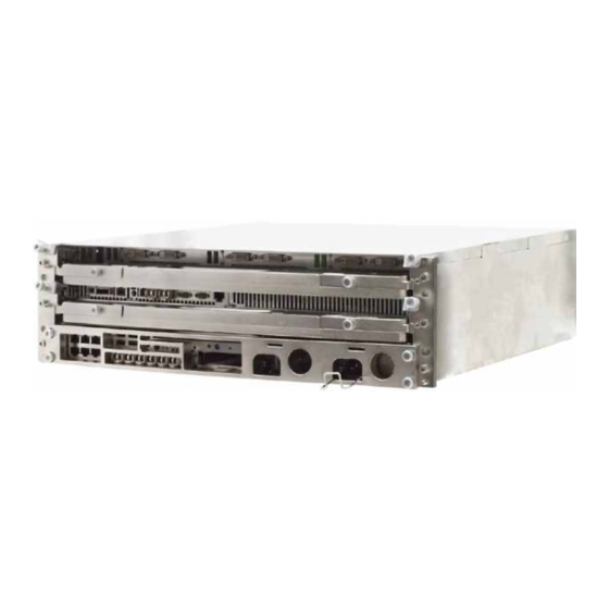
It provides instructions on how to install, configure, power up, and boot the CoolShell 3U (see photo below), which consists of the following 1RU-high compo- nents—all contained in a 3RU-high subrack mountable within a 19” RETMA (Radio Electronics Television Manufacturers Association) rack: Figure 1. - Page 26 Note: Additional information for the RHMI can be achieved by obtaining the CoolShell 3U RHMI Installation Manual (P/N: 117538-024). Each of the CoolShell 3U components is shown in the illustration on the following page, with a generalized CoolShell 3U interconnection flow diagram shown on the page after that.
- Page 27 Preface CPU (Processor) Blade I/O Blade 850W AC Power Supplies (max each) Media Module Figure 2. Individual CoolShell 3U Components xvii Themis Computer...
- Page 28 I C - B PCI-Express I C - A I C - B Media Module PCI-Express + Reset I C - PS1 I C - PS2 AC Power Supplies +12V to All Units Figure 3. Generalized CoolShell 3U Flow Diagram xviii Themis Computer...
- Page 29 Preface A mixture of SMBus (BMC and PCH), I2C bus, and PMBus technology reside within the CoolShell 3U. Table 1 below shows the key differences between the bus architectures found in the CoolShell 3U. Table 1. System Bus Comparison SMBus...
- Page 30 CoolShell 3U Generation 2 Installation Manual Version 1.1 Table 1. System Bus Comparison (Continued) SMBus Specification PMBus High Power Power Capacitance Load per Bus Segment 400pF — 400pF (Max) Rise Time 1µs @ 100kHz, 1µs @ 100kHz, 1µs (Max) 300ns @ 400kHz 300ns @ 400kHz Pull-Up Current at 0.4V...
- Page 31 Product Summation The 3RU-high (5.25”) CoolShell 3U subrack has been designed to fit into a standard 19” rack and has all of the benefits of Themis scalable server systems based on The- mis rugged enterprise server (RES) and “CoolShell” technology; namely: •...
- Page 32 CoolShell 3U Generation 2 Installation Manual Version 1.1 Notes, Cautions, Warnings, and Sidebars The following icons and formatted text are included in this document for the reasons described: Note: A note provides additional information concerning the procedure or action being described.
-
Page 33: Overview And Specifications
Section Chapter Overview and Specifications This chapter gives a general overview of the Themis CoolShell 3U Generation 2 and lists the important specifications associated with the system. Overview—CoolShell 3U The CoolShell 3U (see Figure 1-1 on page 1-2) consists of the following 1RU-high components—all contained in a 3RU-high subrack mountable within a 19”... -
Page 34: Figure 1-1 Coolshell 3U Within Rugged 3Ru Subrack
CoolShell 3U Generation 2 Installation Manual Version 1.1 The front-panel details each of the CoolShell 3U components are shown in Figure 1-2, page 1-2 (CPU Blade), Figure 1-3 (I/O Blade) and Figure 1-4 (AC Power Sup- ply) on page 1-3, and Figure 1-5, page 1-4 (Media Module). -
Page 35: Figure 1-3 I/O Blade Front Panel
1—Overview and Specifications Overview—CoolShell 3U USB 2.0 Ports USB 2.0 Ports LEDs LEDs To CPU Blade Native USB ports for keyboard/mouse PCI-Express I/O Blade Power Primary video used by and bootable USB ports Video Card Link Video Card Link BIOS during boot (DVD / disk / stick) Figure 1-3. -
Page 36: Figure 1-5 Media Module Front Panel
CoolShell 3U Generation 2 Installation Manual Version 1.1 LED ON = Link OK LED Notes: PCI-Express LED OFF = Link Failed 12V Power OK DVD-ROM Boot Drive DVD Activity LED DVD Ejection Button Digital I/O Port (Remote I2C) Pluggable SATA Drive USB 2.0 Ports... -
Page 37: Cpu Blade
1—Overview and Specifications CPU Blade The CPU blade serves as the heart of the CoolShell 3U. The CPU blade comprises a CPU Carrier Board and a X9DRi-F motherboard. Signals are carried from the X9DRi-F PCIe ports to the CPU carrier, where they are then routed to the system backplane and distributed to the various components throughout the system. -
Page 38: Dom (Disk On Module)
1.2.1 DOM (Disk on Module) The CoolShell 3U has one mSATA module (DOM) that attaches to a dedicated mSATA port on the CPU Carrier. The DOM functions as the boot drive for the sys- tem, freeing up the drives in the media module for other activities. OS (operating System) requirements should be stated at the time of order 1.2.2... -
Page 39: 1.2.2.1 Remote On/Off
1—Overview and Specifications 1.2.2.1 Remote On/Off It is possible to remotely turn the CoolShell 3U on and off through the IPMI inter- face. This can be done by using a web browser to access the BMC on the mother- board. The IP address of the IPMI interface is set in BIOS. There is a RJ-45 port located on the face of the CPU blade dedicated to IPMI access. -
Page 40: Figure 1-8 Cpu Blade Lithium Battery
CoolShell 3U Generation 2 Installation Manual Version 1.1 remove the two phillips head screws lift the battery from the socket and remove (view from underneath cover) CPU Blade Figure 1-8. CPU Blade Lithium Battery Themis Computer... -
Page 41: 1.2.3.2 Installing A Lithium Battery
3. Replace the cover on the battery access opening. Replace the two phillips head screws removed in the previous procedure, and hand tighten. 4. Slide the CPU blade back into the CoolShell 3U subrack assembly making sure the CPU blade is properly secured to the CoolShell 3U subrack. -
Page 42: I/O Blade
CoolShell 3U Generation 2 Installation Manual Version 1.1 I/O Blade The I/O Blade houses three NVIDIA Quadro K2000D graphics cards along with two USB 2.0 ports per installed graphics card. 1.3.1 Graphics This I/O blade utilizes NVIDIA’s Quadro K2000D graphics card. The I/O blade will hold up to 3 of the K2000D cards. -
Page 43: Storage Expansion Subsystem
1—Overview and Specifications Storage Expansion Subsystem In addition to the CoolShell 3U and its 3RU subrack, Themis has introduced a Stor- age Expansion Module (see Figure 1-9, page 1-11)—used to provide increased storage—and installed within the same 19” rack above the 3RU subrack. The installer may locate the Subsystem below the 3RU subrack if necessary. -
Page 44: Specifications
Actual weight is dependent on specific system configuration b—Weighed with one power supply installed—system is capable of redundant power supplies if desired 1.5.2 Environmental The CoolShell 3U is designed to meet the environmental requirements listed in Table 1-2. Table 1-2. Environmental Specifications Parameter Operating Non-Operating Temperature 0°... -
Page 45: 1.5.2.1 Shock
1.5.2.3 Noise Level Typical noise levels emitted by the CoolShell 3U are outlined in Table 1-3. The chas- sis is installed with four 38-mm fans contained side-by-side in a single fan assembly. Table 1-3. Typical Noise Levels of the CoolShell 3U... -
Page 46: Rohs Compliance
Design of the CoolShell 3U is compliant with the standards IAW 29 CFR 1910, Sub- part H and Z, FED STD 313, 40 CFR Chapter I, J, abd SD14. The CoolShell 3U does not use ozone-depleting materials as defined in IAW SD 14 and 40 CFR Chap- ter I, Subchapter C. -
Page 47: Table 1-5 I/O Blade Power Specifications
Table 1-5. I/O Blade Power Specifications +3.3V Power +12V Power PCI-Express graphics card 1 3.0A 4.4A PCI-Express graphics card 2 3.0A 4.4A PCI-Express graphics card 3 3.0A 4.4A Total: 9.0A Carrier Board Less than 1A Total maximum current draw: 1-15 Themis Computer... -
Page 48: Packaging And Shipping
AC power cord is 8.5 pounds (4 kg). The approximate weight of a CoolShell 3U with a subrack, component systems, and power supplies is under 40 pounds (18.2 kg) (see Table 1-1 on page 1-12). -
Page 49: Installation And Operation
2.1.1 Subrack Installation Before the CoolShell 3U Generation 2 can be properly installed, follow these steps to attach the empty 3RU subrack to a 19” RETMA rack: 1. Remove any Blades (CPU and I/O), power supplies, and the Media Module—... -
Page 50: Figure 2-2 Install Subrack Alignment Guide-Pins Onto The 19" Rack
CoolShell 3U Generation 2 Installation Manual Version 1.1 Caution: Use industry-standard ESD grounding techniques when handling all electronic components. 2. Install subrack alignment guide-pins to the rear—2 per side—of the 19” rack (see Figure 2-2) with two screws per guide-pin. -
Page 51: Coolshell 3U Installation
3RU Subrack Secured to the 19” Rack 2.1.2 CoolShell 3U Installation Follow these steps to properly install the CoolShell 3U after the 3RU subrack has been firmly attached to the 19” rack: 1. Reinstall each of the CoolShell 3U components (CPU Blade, I/O Blade, Me- dia Module, and power supplies) previously removed from the 3RU subrack. -
Page 52: Figure 2-5 I/O Blade Ports
2-7, page 2-5) and the other ends to an isolated AC wall circuit. This will cause the CoolShell 3U to power on automatically (see following Note). Note: There is no master switch for turning power on or off. Instead, the system becomes active when power supplies are connected to live power. -
Page 53: Multiple Video Displays
The physical video port and the logical number assigned to it are not a fixed relationship. Instead, this is controlled by the sequence of device dis- covery and enumeration during system boot. Themis Computer... -
Page 54: Audio Connection
CoolShell 3U Generation 2 Installation Manual Version 1.1 2.1.4 Audio Connection To establish an audio link, connect the stereo audio cable adapter (shipped with the system, see Figure 2-8) to one of the two audio channels (Channel A or Channel B) -
Page 55: Operation
2.2.1 Power The CoolShell 3U powers on automatically when AC power is supplied to any of the two system power supplies. Once the system backplane and all other components have received power, the motherboard will begin boot process and load the OS. -
Page 56: 2.2.1.2 Remote On/Off
Version 1.1 2.2.1.2 Remote On/Off It is possible to remotely turn the CoolShell 3U on and off through the IPMI inter- face. This can be done by using a web browser to access the BMC on the mother- board. The IP address of the IPMI interface is set in BIOS. When accessing the BMC, the following options for remote power control include: •... -
Page 57: Appendix A. Connector Pinouts
Appendix Connector Pinouts This appendix provides connector pinouts and signal descriptions for the I/O con- nectors installed on the component front panels of the CoolShell 3U Generation 2. CPU Blade A.1.1 Power & Reset Connector Pinouts are described in Figure A-1; signal descriptions are shown in Table A-1. -
Page 58: Table A-1 Power & Reset Connector Pinout Signal Descriptions
CoolShell 3U Generation 2 Installation Manual Version 1.1 Table A-1. Power & Reset Connector Pinout Signal Descriptions Signal Definition Signal Definition Reset Ground Ground SEM = Storage Expansion Module Note: The Power & Reset Connector is used to provide power and reset control from the CPU Blade to the optional SEM (Storage Expansion Module), or other optional subsystems to be developed in the future. -
Page 59: Pci-Express Connector
SEM = Storage Expansion Module Note: The PCI-Express Connector is used to provide data transfer between and the CPU Blade and the optional SEM (Storage Expansion Module), or other op- tional subsystems to be developed in the future. Themis Computer... -
Page 60: Clock & I2C Bus Connector (Firewire 1394
CoolShell 3U Generation 2 Installation Manual Version 1.1 A.1.3 Clock & I2C Bus Connector (Firewire 1394) Pinouts are described in Figure A-3; signal descriptions are shown in Table A-3. Figure A-3. Clock & I2C Connector Pinout Table A-3. Clock & I2C Connector Pinout Signal Descriptions... -
Page 61: Dvi Power Connector (Dvi Transceiver
DVI Power Connector (DVI Transceiver) Pinouts are described in Figure A-1; signal descriptions are shown in Table A-1. Figure A-4. Power & Reset Connector Pinout Table A-4. Power & Reset Connector Pinout Signal Descriptions Signal Definition Signal Definition Themis Computer... -
Page 62: Optical Sfp Ports
The CPU blade has two optical SFP ports on the front of the CPU blade for the pur- pose I2C 4-wire interface (100Mbits/s), and x1 PCIe link transfer. These ports are intended for an expansion unit to be used in conjunction with the CoolShell 3U. CPU Blade... -
Page 63: Ipmi Lan Port
CPU Blade A.1.7 IPMI LAN Port The CoolShell 3U supports one RJ45 Gigabit Ethernet LAN port connector on the front of the CPU module for the purpose of accessing IPMI (see Figure A-7). Pinout signal descriptions are listed in Table A-6. -
Page 64: I/O Blade
CoolShell 3U Generation 2 Installation Manual Version 1.1 I/O Blade Up to three NVIDIA Quadro K2000D graphics cards are installed on an I/O Blade. Each card supports two DVI video output connectors. In addition, associated with each card is one pair of USB 2.0 connectors. -
Page 65: Video Connector Pinout Signal Descriptions
DDC clock No Connection DDC data TDMS Clock Shield Analog VSYNC TDMS Clock+ TDMS Data1– TDMS Clock– TDMS Data1+ Analog R TDMS Data1/3 Shield Analog G No Connection Analog B No Connection Analog HSYNC +5V Power Analog GND Ground Themis Computer... -
Page 66: Media Module
A.3.1 Copper Gigabit Ethernet Ports The CoolShell 3U supports eight copper RJ45 Gigabit Ethernet connectors. Each of the top four connectors contains two status LED indicators one (on the left) indicates lower (primary) RJ45 port activity, and one (on the right) indicates upper (second- ary) RJ45 port activity. -
Page 67: Optical Gigabit Ethernet Ports
Transmit/Receive Data 3 – A.3.2 Optical Gigabit Ethernet Ports The CoolShell 3U supports seven optical Gigabit Ethernet connectors. Note: SFP (Small Form-Factor Pluggable) transceiver ports are provided with optical Ethernet ports. Port designations are described in Figure A-11 on page A-12. -
Page 68: Usb 2.0 Connectors
CoolShell 3U Generation 2 Installation Manual Version 1.1 Receive Transmit SFP Transceiver Port Figure A-11. Optical Gigabit Ethernet Connector Pinout Note: The seven optical Ethernet ports are alternate connections for the first sev- en copper Ethernet ports described in section “Copper Gigabit Ethernet Ports” on page A-10. -
Page 69: Storage Expansion Subsystem
The Clock & I2C Bus connector has the same pinout and signal descriptions as the Clock & I2C Bus connector on the CPU Blade (see Section A.1.3, “Clock & I2C Bus Connector (Firewire 1394),” on page A-4). A-13 Themis Computer... - Page 70 CoolShell 3U Generation 2 Installation Manual Version 1.1 A-14 Themis Computer...
-
Page 71: Bios Setup Utility
BIOS Setup Utility Introduction This chapter describes the AMI BIOS Setup Utility for the CoolShell 3U Generation 2 motherboard X9DRi-F. The AMI ROM BIOS is stored in a Flash EEPROM and can be easily updated. This chapter describes the basic navigation of the AMI BIOS Setup Utility setup screens. -
Page 72: How To Change The Configuration Data
CoolShell 3U Generation 2 Installation Manual Version 1.1 Note: The AMI BIOS has default text messages built in. Supermicro retains the option to include, omit, or change any of these text messages. The AMI BIOS Setup Utility uses a key-based navigation system called “hot keys”. -
Page 73: Main Setup
Date using the arrow keys. Enter new values through the keyboard and press <Enter>. Press the <Tab> key to move between fields. The date must be entered in Day MM/DD/YY format. The time is entered in HH:MM:SS format. Themis Computer... -
Page 74: Supermicro X9Dri
CoolShell 3U Generation 2 Installation Manual Version 1.1 Note: The time is in the 24-hour format. For example, 5:30 P.M. appears as 17:30:00.). B.2.1.2 Supermicro X9DRi • BIOS Build Version: This item displays the BIOS revision used in your sys- tem. -
Page 75: Advanced Setup Configurations
This option allows the bootup screen options to be modified between POST mes- sages or the OEM logo. Select Disabled to display the POST messages. Select Enabled to display the OEM logo instead of the normal POST messages. The options are Enabled (default) and Disabled. Themis Computer... -
Page 76: Addon Rom Display Mode
CoolShell 3U Generation 2 Installation Manual Version 1.1 B.3.1.2 AddOn ROM Display Mode This sets the display mode for the Option ROM. Select Keep Current to use the cur- rent AddOn ROM Display setting. Select Force BIOS to use the Option ROM dis- play mode set by the system BIOS. -
Page 77: Cpu Configuration
Clock Spread Spectrum Select Enable to enable Clock Spectrum support, which will allow the BIOS to mon- itor and attempt to reduce the level of Electromagnetic Interference caused by the components whenever needed. The options are Disabled (default) and Enabled. Themis Computer... -
Page 78: Hyper-Threading
CoolShell 3U Generation 2 Installation Manual Version 1.1 B.3.3.5 Hyper-threading Select Enabled to support Intel Hyper-threading Technology to enhance CPU perfor- mance. The options are Enabled (default) and Disabled. B.3.3.6 Active Processor Cores Set to Enabled to use a processor’s second core and above. The options are All (default), 1, 2, 4, and 6. -
Page 79: Dcu Streamer Prefetcher
Select Energy Efficiency to support power-saving mode. Select Custom to custom- ize system power settings. Select Disabled to disable power-saving settings. The options are Disabled, Energy Efficient (default), and Custom. If the option is set to Custom, the following items will display: Themis Computer... - Page 80 CoolShell 3U Generation 2 Installation Manual Version 1.1 B.3.4.1.1 EIST Available when Power Technology is set to custom. EIST (Enhanced Intel SpeedStep Technology) allows the system to automati- cally adjust processor voltage and core frequency to reduce power consumption and heat dissipation. The options are Disabled (GV3 Disabled), and Enabled (GV3 Enabled) (default).
-
Page 81: Energy/Performance Bias
Recommended Short Duration Power This item displays the short duration power settings recommended by the manufac- turer. B.3.4.6 Short Duration Power Limit This item displays the time period during which short duration power is maintained. The default setting is 0. B-11 Themis Computer... -
Page 82: Chipset Configuration
CoolShell 3U Generation 2 Installation Manual Version 1.1 B.3.5 Chipset Configuration North Bridge This feature allows the user to configure the settings for the Intel North Bridge. Integrated IO Configuration B.3.5.1 Intel VT-d Select Enabled to enable Intel Virtualization Technology support for Direct I/O VT-d by reporting the I/O device assignments to the VWM (Virtual Working Memory) throughout the DMAR ACPI Tables. - Page 83 Select GEN1 to enable PCI-Exp Generation 1 support for Port 3A. Select GEN2 to enable PCI-Exp Generation 2 support for Port 3A. Select GEN3 to enable PCI-Exp Generation 3 support for Port 3A. The options are GEN1, GEN2 (default), and GEN3. B-13 Themis Computer...
- Page 84 CoolShell 3U Generation 2 Installation Manual Version 1.1 B.3.5.12 Port 3C Link Speed Select GEN1 to enable PCI-Exp Generation 1 support for Port 3C. Select GEN2 to enable PCI-Exp Generation 2 support for Port 3C. Select GEN3 to enable PCI-Exp Generation 3 support for Port 3C.
-
Page 85: Qpi Configuration
This section displays the following DIMM information. B.3.5.24 Total Memory This item displays the total memory size available in the system. B.3.5.25 Current Memory Mode This item displays the current memory mode. B.3.5.26 Current Memory Speed This item displays the current memory speed. B-15 Themis Computer... -
Page 86: Dimm Information
CoolShell 3U Generation 2 Installation Manual Version 1.1 B.3.5.27 Mirroring This item displays if memory mirroring is supported by the motherboard. Memory mirroring creates a duplicate copy of the data stored in the memory to enhance data security. B.3.5.28 Sparing This item displays if memory sparing is supported by the motherboard. -
Page 87: Demand Scrub
When the CPU or I/O issues a demand-read com- mand, and the read data from memory turns out to be a correctable error, the error is corrected and sent to the requestor (the original source). Memory is updated as well. B-17 Themis Computer... -
Page 88: Data Scrambling
CoolShell 3U Generation 2 Installation Manual Version 1.1 Select Enabled to use Demand Scrubbing for ECC memory correction. The options are Enabled and Disabled (default). B.3.5.40 Data Scrambling Select Enabled to enable data scrambling to ensure data security and integrity. The options are Disabled (default) and Enabled. -
Page 89: All Usb Devices
When this submenu is selected, the AMI BIOS automatically detects the presence of IDE or SATA devices and displays the following items: B.3.6.1 SATA Port0~SATA Port5 The AMI BIOS displays the status of each SATA port as detected by the BIOS. B-19 Themis Computer... -
Page 90: Sata Mode
CoolShell 3U Generation 2 Installation Manual Version 1.1 B.3.6.2 SATA Mode Use this feature to configure SATA mode for a selected SATA port. The options are Disabled, IDE Mode, AHCI Mode (default), and RAID Mode. The following are displayed depending on your selection:... -
Page 91: Scu (Storage Control Unit) Configuration
ME SMBus Thermal Reporting This feature appears when Thermal Management is set to Enabled. Select Enabled to support ME SMBus (Management Engine System Management Bus) reporting. The options are Enabled and Disabled (default). When Enabled, the following appear: B-21 Themis Computer... -
Page 92: Pcie/Pci/Pnp Configuration
CoolShell 3U Generation 2 Installation Manual Version 1.1 B.3.8.2.15 PCH Temp Read, CPU Energy Read, CPU Temp Read Set the above items to Enabled to activate these monitors. The options are Enabled (default) and Disabled. B.3.8.2.16 Alert Enable Lock Set this item to Enabled to lock all Alert Enable settings. The options are Enabled and Disabled (default). -
Page 93: Serr# Generation
Select Enabled to enable the onboard LAN1 Options ROM~LAN2 Option ROM. This is to boot the computer using a network device. The default setting for LAN1 Option ROM is Enabled (default), and the default setting for LAN2 Option ROM is Disabled (default). B-23 Themis Computer... -
Page 94: Vga Priority
CoolShell 3U Generation 2 Installation Manual Version 1.1 B.3.9.11 VGA Priority This feature allows the user to select the graphics adapter to be used as the primary boot device. The options are Onboard (default) and Offboard. B.3.9.12 Network Stack Select Enabled to enable PXE or UEFI (Unified Extensible Firmware Interface) for network stack support. -
Page 95: Serial Port Console Redirection
A lower transmission speed may be required for long and busy lines. The options are 9600, 19200, 38400, 57600, and 115200 (bits per second) (default). B.3.11.5 Data Bits Use this feature to set the data transmission size for Console Redirection. The options are 7 Bits and 8 Bits (default). B-25 Themis Computer... -
Page 96: Stop Bits
CoolShell 3U Generation 2 Installation Manual Version 1.1 B.3.11.6 Parity A parity bit can be sent along with regular data bits to detect data transmission errors. Select Even if the parity bit is set to 0, and the number of 1’s in data bits is even. -
Page 97: B.3.11.14 Console Redirection
Make sure that the same speed is used in the host computer and the client computer. A lower transmission speed may be required for long and busy lines. The options are 9600, 19200, 38400, 57600, and 115200 (bits per second) (default). B-27 Themis Computer... -
Page 98: Acpi Settings
CoolShell 3U Generation 2 Installation Manual Version 1.1 B.3.11.18 Flow Control This feature allows the user to set the flow control for Console Redirection to pre- vent data loss caused by buffer overflow. Send a “Stop” signal to stop sending data when the receiving buffer is full. -
Page 99: Tpm Support
• TXT Support - Indicates if TXT support is enabled or disabled. The default setting is Disabled (default). • Intel TXT Dependencies - Displays a list of features that must be supported (and enabled) before Intel TXT(LT-SX) configuration can be enabled. B-29 Themis Computer... -
Page 100: Me (Management Engine) Subsystem
CoolShell 3U Generation 2 Installation Manual Version 1.1 B.3.13 ME (Management Engine) Subsystem This feature displays the following Intel ME Subsystem Configuration settings. B.3.13.1 ME Subsystem Select Enabled to support Intel Management Engine (ME) Subsystem, a small power computer subsystem that performs various tasks in the background. The options are Enabled (default) and Disabled. -
Page 101: Event Logs
This feature allows the user to configure SMBIOS Event Settings. Enabling/Disabling Options B.4.1.1 SMBIOS Event Log Select Enabled to enable SMBIOS (System Management BIOS) Event Logging dur- ing system boot. The options are Enabled (default) and Disabled. B-31 Themis Computer... -
Page 102: Erase Event Log
CoolShell 3U Generation 2 Installation Manual Version 1.1 Erasing Settings B.4.1.2 Erase Event Log This option erases all logged events. The options are No (default), Yes, Next reset, and Yes, Every reset. B.4.1.3 When Log is Full Select Erase Immediately to immediately erase SMBIOS error event logs that exceed the limit when the SMBIOS event log is full. -
Page 103: Ipmi
Select the IPMI (Intelligent Platform Management Interface) tab to access the fol- lowing submenu items. Figure B-4. IPMI Settings IPMI Firmware Revision This item indicates the IPMI firmware revision used in your system. IPMI Status This item indicates the status of the IPMI firmware installed in your system. B-33 Themis Computer... -
Page 104: System Event Log
CoolShell 3U Generation 2 Installation Manual Version 1.1 B.5.1 System Event Log Enabling/Disabling Options B.5.1.1 SEL Components Select Enabled for all system event logging at bootup. The options are Enabled (default) and Disabled. Erase Settings B.5.1.2 Erase SEL Select Yes, On next reset to erase all system event logs upon next system reboot. -
Page 105: Update Ipmi Lan Configuration
This item displays the Router IP address for this computer. This should be in decimal and in dotted quad form (i.e., 192.168.10.253). B.5.2.8 Router MAC Address This item displays the Router Mac address for this computer. Mac addresses are 6 two-digit hexadecimal numbers. B-35 Themis Computer... -
Page 106: Boot Configuration
CoolShell 3U Generation 2 Installation Manual Version 1.1 Boot Configuration Use this feature to configure boot settings. Figure B-5. Boot Settings B.6.1 Boot Option Priorities B.6.1.1 Boot Option #1/ Boot Option #2/ Boot Options #3, etc. Use this feature to specify the sequence of boot device priority. -
Page 107: Delete Boot Option
This feature allows the user to delete a previously defined boot device from which the system boots during startup. B.6.3 Boot Option #1, Boot option #2, Boot Option #3 The settings are Built-in EFI Shell, and [any pre-defined boot device]. B-37 Themis Computer... -
Page 108: Security Settings
CoolShell 3U Generation 2 Installation Manual Version 1.1 Security Settings This menu allows the user to configure the following security settings Figure B-6. Security Settings B.7.1 Administrator Password Use this feature to set the Administrator Password which is required to enter the BIOS setup utility. -
Page 109: Exit Options
<Enter>. When the dialog box appears, asking you if you want to exit the BIOS setup without saving, click Yes (default) to quit BIOS without saving the changes, or click No to quit the BIOS and save changes. B-39 Themis Computer... -
Page 110: Save Changes And Reset
CoolShell 3U Generation 2 Installation Manual Version 1.1 B.8.2 Save Changes and Reset When you have completed the system configuration changes, select this option to save the changes and reboot the computer so that the new system configuration set- tings can take effect. Select Save Changes and Exit, and press <Enter>. When the... -
Page 111: Restore User Defaults
No to abandon the user's defaults that were previously saved. B.8.8 Boot Override This feature allows the user to override the Boot Option Priorities setting in the Boot menu, and Instead boot the system with one of the listed devices. B-41 Themis Computer... -
Page 112: Bios Error Beep Codes
• Fatal errors: errors that will not allow the system to continue with the bootup procedure. If a fatal error occurs, contact Themis Support for possible repairs. These errors are usually communicated through a series of audible beeps. The table below describes the number of beeps with the corresponding error state. -
Page 113: Bios Recovery
USB drive. 2. While turning the power on, press and hold <Ctrl> and <Home> at the same time until the USB Access LED Indicator comes on. This might take a few seconds. B-43 Themis Computer... -
Page 114: Boot Sector Recovery From An Ide Cd-Rom
CoolShell 3U Generation 2 Installation Manual Version 1.1 3. Once the USB drive LED is on, release the <Ctrl> and <Home> keys. AMI- BIOS will issue beep codes to indicate that the BIOS ROM file is being updated. 4. When BIOS flashing is completed, the computer will reboot. Do not interrupt the flashing process until it is completed. - Page 115 BIOS file is being uploaded. 7. To use Hyper Terminal to transfer the XModem protocol by using the “Send File” dialog under the “Transfer” menu, follow the instructions below to com- plete XModem transfers. B-45 Themis Computer...
-
Page 116: Figure B-8 Ami_Flsh Hyperterminal
CoolShell 3U Generation 2 Installation Manual Version 1.1 a. Select the “Transfer” menu and enter <Send> (see Figure B-8). Figure B-8. AMI_FLSH Hyperterminal b. Specify the location of the ROM file and select the proper protocol (XMo- dem). c. Press <Send> to start ROM File extraction. (see Figure B-9) Figure B-9. -
Page 117: Figure B-10 Flash Recovery
VT-100 and XModem protocols, including protocols designed for GNU/LINUX & BSD operating systems such as minicom. It is recommended that the terminal program be configured to use the “CR/LF” style of line termina- tion. B-47 Themis Computer... - Page 118 CoolShell 3U Generation 2 Installation Manual Version 1.1 B-48 Themis Computer...
-
Page 119: Appendix C. X9Dri-F Motherboard
X9DRi-F motherboard, located in the CPU blade of the CoolShell 3U Generation 2. Note: These are purely X9DRi-F motherboard features. Thus, not all features may be realized through the CPU blade, or the CoolShell 3U system as a whole. These specifications and features should serve for informational purposes only. -
Page 120: Table C-1 X9Dri-F Motherboard Options
CoolShell 3U Generation 2 Installation Manual Version 1.1 Figure C-1. X9DRi-F Motherboard Table C-1. X9DRi-F Motherboard Options PCI-e 3.0 Slots Memory Motherboard IPMI SATA Graphics Audio Slots PCI-e PCI-e X8DTi-F a—Super Micro Computer, Inc. Themis Computer... -
Page 121: Table C-2 Major Features Of The X9Dri-F
Three RJ-45 LAN ports (one dedicated for IPMI) Motherboard I/O • VGA port • Two Fast UART 16550 ports • Eleven USB 2.0 ports • DOM (Disk on Module) power connector Dimensions 12” x 13” (30.5cm x 33.2cm); E-ATX form factor Themis Computer... -
Page 122: Figure C-2 X9Dri-F Block Diagram
CoolShell 3U Generation 2 Installation Manual Version 1.1 Figure C-2. X9DRi-F Block Diagram Themis Computer... -
Page 123: Figure C-3 X9Dri-F Motherboard
Lithium Battery (CR032) P1 DIMM C1 P1 DIMM C2 P1 DIMM D1 P1 DIMM D2 P1 DIMM B2 P1 DIMM B1 P1 DIMM A2 P1 DIMM A1 Figure C-3. X9DRi-F Motherboard Themis Computer... -
Page 124: Chipset Overview
CoolShell 3U Generation 2 Installation Manual Version 1.1 Chipset Overview Built upon the functionality and capability of the Intel® E5-2600 V2 Series Proces- sor (Socket R) and the PCH C602 Chipset. X9DRi-F provides the performance required for dual processor-based high-end systems, including optimal configuration options for communications, high-end CAD systems, or database applications. - Page 125 • Error detection via CRC and Error correction via Link level retry • ACPI Power Management Logic Support for Rev. 3.0b or Rev 4.0 ® • Intel Rapid Storage Technology ® • Intel Trusted Execution Technology • Serial Peripheral Interface (SPI) • Digital Media Interface (DMI) Themis Computer...
-
Page 126: Special Features
CoolShell 3U Generation 2 Installation Manual Version 1.1 Special Features C.3.1 Recovery from AC Power Loss The BIOS setup can be configured to allow the system, whenever AC power is lost, • to remain off (power switch must be pressed to turn system back on) or •... -
Page 127: C.3.2.3 System Resource Alert
When the CPU enters a suspend state, the Power LED will start blinking to indicate that the CPU is in suspend mode. Pressing any key on the keyboard will awaken the CPU, at which time the power LED will stop blinking and remain on. Themis Computer... -
Page 128: Super I/O
CoolShell 3U Generation 2 Installation Manual Version 1.1 C.3.5 Super I/O The Super I/O supports two high-speed,16550 compatible serial communication ports (UARTs). Each UART includes a 16-byte send/receive FIFO, a programmable baud rate generator, complete modem control capability and a processor interrupt system. - Page 129 • Supports Management tools: IPMIView, CLI (Command Line Interface) • RMCP+ protocol supported Note: For more information on the Motherboard’s IPMI configuration, please re- fer to the IPMI User’s Guide posted on the SuperMicro website at, www.super- micro.com/support/manuals/. C-11 Themis Computer...
- Page 130 CoolShell 3U Generation 2 Installation Manual Version 1.1 C-12 Themis Computer...
-
Page 131: Appendix D. Red Hat Enterprise Linux 5 Installation
DVD device. From fundamental concepts such as installation preparation to the step-by-step installation procedure. Please specify all OS needs when placing your order, as this information is vital for Themis to insure that hardware and OS integrate properly. Note: For addition information regarding Red Hat ®... -
Page 132: Figure D-1 Power On After Linux Dvd Is Inserted Into Drive
CoolShell 3U Generation 2 Installation Manual Version 1.1 Figure D-1. Power On after Linux DVD is Inserted into Drive Step 2: Press the “tab” key to move focus to the “Skip” key, then press “Enter” key to Continue (see Figure D-2). -
Page 133: Figure D-3 Welcome Screen
Selecting the appropriate language also helps target your time zone configuration later in the installation. The installation program tries to define the appropriate time zone based on what you specify on this screen (see Figure D-4 on page D-4). Themis Computer... -
Page 134: Figure D-4 Language Selection
CoolShell 3U Generation 2 Installation Manual Version 1.1 Figure D-4. Language Selection Once you select the appropriate language, click Next to continue. Step 5: Using your mouse, select the correct layout type (for example, U.S. Eng- lish) for the keyboard you would prefer to use for the installation and as the system default (see Figure D-5 on page D-5). -
Page 135: Figure D-5 Selecting Layout Type
Step 6: Enter the installation number, if you don’t have an installation number; select the Skip Entering Installation Number Radio Button. Click OK, and if you did not enter an installation number, you’ll be given a warning. Click Skip to continue (see Figure D-6 on page D-6). Themis Computer... -
Page 136: Figure D-6 Enter Installation Number
CoolShell 3U Generation 2 Installation Manual Version 1.1 Figure D-6. Enter Installation Number Click Next to continue. Step 7: Partitioning allows you to divide your storage drive into isolated sections, where each section behaves as its own drive. Partitioning is particularly useful if you run multiple operating systems. -
Page 137: Figure D-7 Partitioning
Using your mouse, choose the storage drive(s) on which you want Red Hat Enter- prise Linux to be installed. If you have two or more drives, you can choose which drive(s) should contain this installation. Unselected drives, and any data on them, are not touched. Themis Computer... -
Page 138: Figure D-8 Reviewing Option
CoolShell 3U Generation 2 Installation Manual Version 1.1 To review and make any necessary changes to the partitions created by automatic partitioning, select the Review option. After selecting Review and clicking Next to move forward, the partitions created for you in Disk Druid appear. You can make modifications to these partitions if they do not meet your needs (see Figure D-8). -
Page 139: Figure D-9 Creating A Custom Layout
“No” Boot Loader will be Installed, you’ll need to use a third-party boot loader such as Partition Magic or Microsoft’s TLDR, unless you want to set up a Boot Loader Password or Configure Advanced Boot Loader Options (see Figure D-10 on page D-10). Themis Computer... -
Page 140: Figure D-10 Setting Up Boot Loader
CoolShell 3U Generation 2 Installation Manual Version 1.1 Figure D-10. Setting Up Boot Loader To configure more advanced boot loader options, such as changing the drive order or passing options to the kernel, be sure Configure advanced boot loader options is selected before clicking Next. -
Page 141: Figure D-11 Master Boot Record (Mbr
BIOS does not return the correct drive order. Changing the drive order may be useful if you have multiple SCSI adapters, or both SCSI and IDE adapters, and you want to boot from the SCSI device. Click Next. D-11 Themis Computer... -
Page 142: Figure D-12 Network Devices List
CoolShell 3U Generation 2 Installation Manual Version 1.1 Step 12: The installation program automatically detects any network devices you have and displays them in the Network Devices list (see Figure D-12). Figure D-12. Network Devices List Step 13: Once you have selected a network device, click Edit. From the Edit... -
Page 143: Figure D-13 Edit Interface Pop-Up Screen
A red X appears indicating your selection. • You can also scroll through the list at the bottom of the screen to select your time zone. Using your mouse, click on a location to highlight your selection. D-13 Themis Computer... - Page 144 CoolShell 3U Generation 2 Installation Manual Version 1.1 Figure D-14. Selecting Time Zone Click Next. Step 15: Setting up a root account and password is one of the most important steps during your installation. Your root account is similar to the administrator account used on Windows NT machines.
- Page 145 Clicking Next takes you to the Package Group Selection screen. You can select package groups, which group components together according to func- tion (for example, X Window System and Editors), individual packages, or a combi- nation of the two. D-15 Themis Computer...
- Page 146 CoolShell 3U Generation 2 Installation Manual Version 1.1 To select a component, click on the checkbox beside it Figure D-16. Package Installation Default Screen Step 17: Select each component you wish to install. Once a package group has been selected, if optional components are available you...
- Page 147 Once you have selected the package groups of your choice, you get one last Step 18: chance to go back before starting the installation process. Click Next if you’re happy with your choices, or click Back to make changes (see Figure D-18 on page D-18). D-17 Themis Computer...
- Page 148 CoolShell 3U Generation 2 Installation Manual Version 1.1 Figure D-18. Option to Review or Continue Click Next. Step 19: Installation Starts (see Figure D-19 on page D-18). Figure D-19. Installation Begins D-18 Themis Computer...
- Page 149 • Do nothing — after the boot loader's timeout period, (by default, five seconds) the boot loader automatically boots the default boot entry. Do whatever is appropriate to boot Red Hat Enterprise Linux. One or more screens of messages should scroll by. D-19 Themis Computer...
- Page 150 CoolShell 3U Generation 2 Installation Manual Version 1.1 Step 21: Eventually, a login: prompt or a GUI login screen (if you installed the X Window System and chose to start X automatically) appears (see Figure D-21). Figure D-21. Login Screen Step 22: Once logged in, you are ready to use the desktop (see Figure D-22).
-
Page 151: Index
AddOn ROM Display Mod B-6 USB 2.0 Controller Mode B-17 Bootup Num-Lock B-6 USB Functions B-16 Hit ’Del’ Message Display B-6 Super IO Device Configuration B-24 Interrupt 19 Capture B-6 Serial Port1 Address B-24 Quick Boot B-5 alignment holes, subrack 2-2 Index-1 Themis Computer... - Page 152 CoolShell 3U Generation 2 Installation Manual Version 1.1 AMI BIOS B-1 Clock & Connector Pinout Signal AMI_FLSH Hyperterminal Screen B-46 Descriptions A-4 applications 2-8 Comments xxi Audio Cable Adapter 2-6 connector pinouts A-1, C-1 audio channels (Channel A or Channel B) 2-6...
- Page 153 Video Connector Pinout A-9 Video Connector Pinout Signal Main BIOS Setup Screen B-3 Descriptions A-9 Media Module xvi, 1-1, A-10 I/O Blade Power Specifications 1-15 Copper Gigabit Ethernet Connector I/O connectors A-1 Pinout A-10 Installation procedures 2-1 Index-3 Themis Computer...
- Page 154 CoolShell 3U Generation 2 Installation Manual Version 1.1 Copper Gigabit Ethernet Connector Pinout pinouts, connector A-1, C-1 Signals and LED Interpretation A-11 PIO Mode B-22 Copper Gigabit Ethernet Ports A-10 Power & Reset Connector A-1, A-5, A-13 Front Panel 1-4 Power &...
- Page 155 SuperDoctor III C-9 System Fan Monitor B-28 system ID 2-8 System Tools 2-8 system tools 2-8 temperature xxi Temperature Rise B-15 Themis Customer Support ii trademarks ii USB 2.0 Connector Pinout A-8, A-12 Connector Pinout Signal Descriptions A-8, A-12 Index-5...
- Page 156 CoolShell 3U Generation 2 Installation Manual Version 1.1 Index-6 Themis Computer...
- Page 157 Place Stamp Here Themis Computer 47200 Bayside Parkway Fremont, CA 94538 Attn: Publications Department Fold here; tape at top to seal...
-
Page 158: Reader Comment Card
Reader Comment Card We welcome your comments and suggestions to help improve the CoolShell 3U Generation 2 Installation Manual. Please take time to let us know what you think about this manual. • Information provided in the manual was complete.
Need help?
Do you have a question about the CoolShell 3U and is the answer not in the manual?
Questions and answers