Focal Point elysee radiant Installation & User's Instructions

Focal Point elysee radiant Installation & User's Instructions

Full depth radiant/convector inset gas fire

Advertisement

INSTALLATION & USER INSTRUCTIONS
FULL DEPTH RADIANT/CONVECTOR INSET GAS FIRE
Focal Point Fires plc.
Christchurch, Dorset BH23 2BT
Tel: 01202 499330
Fax: 01202 499326
www.focalpointfires.co.uk
e : sales@focalpointfires.co.uk
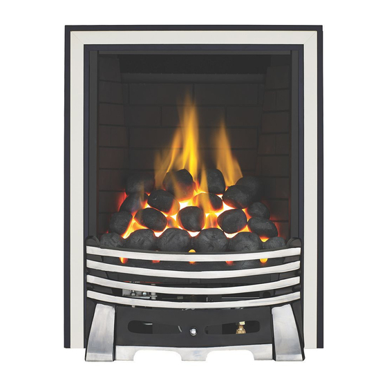
EXCELSIOR RADIANT
IN THE UK ALWAYS USE A GAS SAFE REGISTERED ENGINEER TO INSTALL, REPAIR OR SERVICE THIS APPLIANCE
Please note : Except where otherwise stated, all rights,
including copyright in the text, images and layout of this
booklet is owned by Focal Point Fires plc. You are not per-
mitted to copy or adapt any of the content without the
prior written permission of Focal Point Fires plc.
MODELS COVERED BY THESE INSTRUCTIONS
ELYSEE RADIANT
EXCELSIOR RADIANT
EXCELSIOR CONVECTOR
SUPA 400 DELUXE
1
EXCELSIOR RADIANT
Please note : All colour/finish variants are not shown.
All instructions must be handed to the user for
safekeeping.
Revision A - 11/11
GB IE
F500007
F500428
F500267
F500008
BS7977-1 : 2009
BS EN 509 : 2000
KM579168
EXCELSIOR CONVECTOR
© 2011 Focal Point Fires plc.

Advertisement

Table of Contents
loading
Need help?

Need help?

Do you have a question about the elysee radiant and is the answer not in the manual?

Questions and answers

Subscribe to Our Youtube Channel

Summary of Contents for Focal Point elysee radiant

  • Page 1 Please note : All colour/finish variants are not shown. including copyright in the text, images and layout of this booklet is owned by Focal Point Fires plc. You are not per- All instructions must be handed to the user for mitted to copy or adapt any of the content without the safekeeping.
  • Page 2: Table Of Contents

    Remote control Handset requirements - 1 x ‘PP3’ type (9 volt) Receiver/motor unit requirements - 4 x ‘AA’ type (1.5 volt) Refer to the appropriate section of these instructions for details of how to change the batteries. © 2011 Focal Point Fires plc.
  • Page 3: Appliance Data

    DEPTH should be 307mm or greater for a flue which has been used for solid fuel of oil burning appliances. Opening DEPTHS include any plaster or infill panels which form part of the installation. Opening DEPTHS include any plaster or infill panels which form part of the installation. © 2011 Focal Point Fires plc.
  • Page 4: Debris Collection Space

    CLAY/CEMENT LINES OR BLOCK FLUE WHICH IS NEW, UNUSED, OR PREVIOUSLY ONLY USED WITH A GAS FIRE. X Dimension = 20mm UNLINED FLUE OR CHIMNEY WHICH HAS BEEN PREVIOUSLY USED FOR A SOLID FUEL OR OIL BURNING APPLIANCE X Dimension = 60mm © 2011 Focal Point Fires plc.
  • Page 5: Ventilation

    Cable fixing kit; 2 cables, 2 tensioners, 2 cable clamps, 4 eyebolts, 4 wall plugs Sealing grommet Lengths of adhesive sealing strip Self tapping screw pack; 4 No8 x 5/16 Set of manufacturers instructions © 2011 Focal Point Fires plc.
  • Page 6: Preparing The Appliance

    SEALING STRIPS : Apply the self adhesive sealing strips to the back of the fireframe as shown in figure 8 to give a continuous seal. Figure 8 © 2011 Focal Point Fires plc.
  • Page 7: Preparing The Opening

    Not to scale © 2011 Focal Point Fires plc.
  • Page 8: Installation By Cable Fixing Kit

    Turn on and test the gas supply up to the fire for any leaks, in accordance with current edition of BS6891. When the appliance is first used, protective oils coating the firebox may burn off. It is advisable to ventilate the room during this period for at least one hour. © 2011 Focal Point Fires plc.
  • Page 9: Operating The Fire (Slide Control)

    It is necessary to press buttons 1 and 2 (see figure 18) simulta- Figure 18 neously to turn the fire up. To turn the fire down press button 3 only. © 2011 Focal Point Fires plc.
  • Page 10: Spark Gap

    10 minutes and repeat the test. When the test has been completed satisfactorily, repeat with any extractor fans in the premises running on the highest setting, and any communicating doors open. Finally, repeat with all doors open. © 2011 Focal Point Fires plc.
  • Page 11: Briefing The Customer

    Where necessary replace damaged components with genuine spares. Seal scrap ceramic components in plastic bags and dispose at proper refuse sites as directed. Re-fit the ceramics by referring to the relevant section of these instructions. © 2011 Focal Point Fires plc.
  • Page 12: Removing The Burner

    Appliance - Ensure appliance is off and cool. Remove cover from top of receiver box. The cover is protected by reflective foil, and located towards the right hand side, underneath the burner unit. Insert 4 x ‘AA’ (1.5 volt) batteries - Replace cover. © 2011 Focal Point Fires plc.
  • Page 13: Troubleshooting Guide

    • Spillage occurring. Carry out Spillage test and rectify any problems. • Combustible materials used in incorrect positions. • Firebox grommet seal missing, rectify. • Other airborne contaminants such as dust, tobacco smoke, paint vapours. © 2011 Focal Point Fires plc.
  • Page 14 For Republic of Ireland, ventilation may be required, see IS 813, ICP3, IS 327, and any other rules in force. WARNING : Ventilation openings (where fitted) must never be blocked or restricted in any way. © 2011 Focal Point Fires plc.
  • Page 15 Figure 4 activated or turned up accidentally. It is necessary to press buttons 1 and 2 (see figure 4) simultane- ously to turn the fire up. To turn the fire down press button 3 only. © 2011 Focal Point Fires plc.
  • Page 16: Flue Spillage Monitoring System

    Again, remember not to push the coals down too far into the valleys between the coal supports as this can have a detrimental effect to the flame picture. © 2011 Focal Point Fires plc.
  • Page 17: Fuel Bed Layout - Pebble Effect

    Again, remember not to push the peb- bles down too far into the valleys between the supports as this can have a detrimental effect to the flame picture. © 2011 Focal Point Fires plc.
  • Page 18: Fuel Bed Layout - Log Effect

    Place the log numbered 15 on the right hand side as also shown in figure 19, again ensuring correct orientation. Both these logs will fit securely into their allocated position, they may require rotating slightly to ensure this. © 2011 Focal Point Fires plc.
  • Page 19: Servicing

    Appliance - Ensure appliance is off and cool. Remove cover from top of receiver box. The cover is protected by reflective foil, and located towards the right hand side, underneath the burner unit. Insert 4 x ‘AA’ (1.5 volt) batteries - Replace cover. © 2011 Focal Point Fires plc.
  • Page 20: List Of Replacement Parts

    Contact details of Engineer As our policy is one of continuous improvement and development , we hope therefore you will understand we must retain the right to amend details and/or specifications without prior notice. © 2011 Focal Point Fires plc.

Table of Contents