Table of Contents
Advertisement
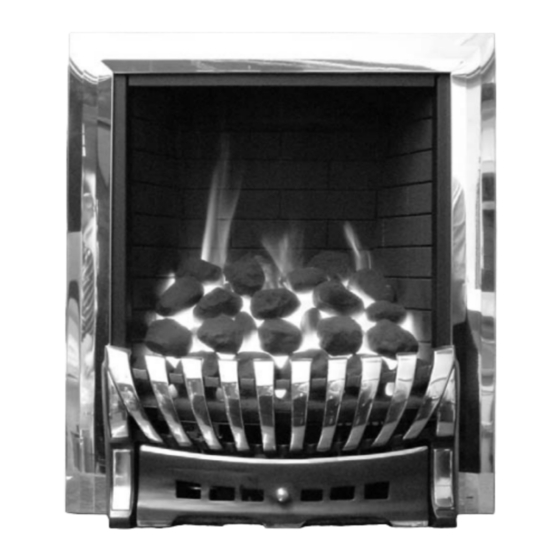
FULL D D EPTH G G AS F F IRE
MANUAL O O R R R EMOTE C C ONTROL
RANGE
BLENHEIM S S TYLE
ELEGANCE
LULWORTH
INSTALLATION A A ND U U SER
INSTRUCTIONS
All i i nstructions m m ust b b e h h anded t t o u u ser f f or s s afekeeping
Revision A - 05/04
Country(s) of destination - GB/IE
Focal Point Fires plc, Christchurch, Dorset BH23 2BT
Tel: 01202 499330
Fax: 01202 499326
www.focalpoint.co.uk
e-mail: sales@focalpointfires.co.uk
Advertisement
Table of Contents

Related Manuals for Focal Point Blenheim Style


Summary of Contents for Focal Point Blenheim Style
- Page 1 All i i nstructions m m ust b b e h h anded t t o u u ser f f or s s afekeeping Revision A - 05/04 Country(s) of destination - GB/IE Focal Point Fires plc, Christchurch, Dorset BH23 2BT Tel: 01202 499330 Fax: 01202 499326 www.focalpoint.co.uk...
- Page 2 Blenheim Style Elegance Lulworth...
- Page 3 INST T ALLAT T ION I I NST T RUCT T IONS P P relim m in n ary N N otes B B efore I I n n stallation n This appliance is an Inset Live Fuel Effect appliance that provides radiant warmth utilising the latest type burner technology.
-
Page 4: Important N N Otes
Sec c tion Contents s Pag g e N N o. Sec c tion Contents s Pag g e N N o. Important Notes 11.0 Fitting the Firebox Appliance Data 11.1 Installation by Cable Fixing Kit Installation Requirements 12.0 Fuel Bed Layout (coal versions) Site Requirements 12.1 Fuel Bed Layout (pebble versions) -
Page 5: Appliance D D Ata
APPLIANCE D D ATA Manual Control Version Remote Control Version Gas Group G20 Natural Gas CAT I2H G20 Natural Gas CAT I2H Inlet Pressure 20 mbar 20 mbar Max Energy Input (gross) 6.8 kW 6.8 kW Min Energy Input (gross) 3.5 kW 3.5 kW Pilot Energy Input (gross) -
Page 6: Site R R Equirements
SITE R R EQUIREMENTS The fireplace opening should be inspected and repairs made where necessary. Any chair brick or fireback may be left in situ, providing that the dimensional requirements for debris collection space and spigot clearances are met. See diagram below.. The opening WIDTH and HEIGHT dimensions should be between 375mm and 450mm wide, and 540mm (see n n ote b b elow) to 575mm high. -
Page 7: Unpacking The Appliance
DEBRIS C C OLLECTION S S PACE The mounting depth of this appliance is 180mm. In accordance with BS 5871 part 2, minimum debris collection volumes are required behind the installed appliance. These are shown in the table below and as dimension X on the fireplace diagram shown previously. CLAY/ / CEMENT L L INES O O R B B LOCK F F LUE W W HICH I I S N N EW, , U U NUSED, , O O R P P REVIOUSLY O O NLY U U SED W W ITH A A G G AS F F IRE. - Page 8 COMPONENT C C HECKLIST QUANTITY DESCRIPTION Firebox and burner tray assembly Decorative frame (either magnetic type or 3 piece clip-on type) Cast or fabricated firefront with separate ashpan door Moulded ceramic fibre combustion matrix Moulded ceramic front strip Individual ceramic coals (coal effect versions) Individual ceramic pebbles (pebble effect versions) Ceramic brick effect radiant panels Ceramic brick panel retaining clips...
-
Page 9: Fitting The Decorative Frame
FITTING THE DECORATIVE FRAME The appliance is supplied with a decorative frame. The frame attaches to the firebox using either four magnetic pieces, or as a three piece clip-on assembly. If a three piece clip on frame is to be fitted, and the firebox is to be retained by the cable method, this is the most convenient stage at which to do so. -
Page 10: Fitting The Firebox
10.0 GAS S S UPPLY R R OUTING ( ( continued) The gas pipe must be suitably protected where it passes through fireplace openings. Any sleeving should be sealed to the pipe at its ends. This appliance is fitted with an inlet restictor elbow. The open end of the supply pipe should be sealed temporarily during the installation of the firebox to prevent the ingress of dirt and dust. -
Page 11: Gas Connection
11.3 GAS CONNECTION Purge the gas supply thoroughly to remove air and dirt/debris BEFORE connection. Now disconnect the inlet restrictor elbow from the inlet pipe. Connect the previously installed gas supply to inlet restrictor elbow, and re-fit the restrictor elbow to the inlet pipe of the appli- ance. -
Page 12: Fuel Bed Layout
12.0 FUEL BED LAYOUT ( ( continued) 5. Now take another four coals and place behind the second row of coals, in order to complete the third row. The coals may be orien- tated as desired to achieve a realistic effect. Keep the spacing between the coals even and uniform. -
Page 13: Fitting The Firefront
12.1 FUEL BED LAYOUT ( ( continued) 4. Now take another two pebbles and place behind the second row of coals, next to each other in the centre of the fuel bed. The peb- bles may be orientated as desired to achieve a realistic effect. Keep the spacing between the pebbles even and uniform. -
Page 14: Spark Failure
14.2 OPERATING T T HE F F IRE ( ( remote c c ontrol v v ersions) The gas valve has two control knobs ; Turn the main burner control (shown on left hand side of control valve) knob fully anti-clockwise. Turn ignition knob (shown on right hand side of control valve) slightly left towards the ignition position until reaching the stop, press down and hold for a few seconds until pilot gas is flowing. -
Page 15: Testing For Spillage
14.7 TESTING FOR SPILLAGE Close all doors and windows to the room containing the appliance. Let the fire run on HIGH for five minutes. Take a smoke match, light it, and using a smoke match tube, hold it at the top edge of the fire opening, 25mm down and 25mm in. Starting 50mm in from either side, run the smoke match across the opening. -
Page 16: Pilot Assembly
15.0 SERVICING - c c ontinued 11. Strip off the burner pipes and clean thoroughly. 12. Clean out the injector, pilot assembly and burner tube. DO NOT remove the pilot injector. 13. Re-assemble and re-fit the burner tray. 14. Turn on the gas supply, and leak test. 15. -
Page 17: Troubleshooting G G Uide
16.0 TROUBLESHOOTING G G UIDE Fire s s parks b b ut p p ilot d d oes n n ot l l ight No gas to fire, check isolators are open. Pipework blockage, clean out. Air not fully purged, repurge supply or wait longer. Spark earthing to metal work, reset gap correctly. - Page 18 USER INST T RUCT T IONS Sec c tion Contents s Pag g e N N o. Important Notes Firefront Clearances to Combustibles Ventilation Operating Instructions Flue Spillage Monitoring System Cleaning Cleaning the Ceramics Servicing 10.0 List of spare parts IMPORTANT N N OTES The installation of this fire MUST only be carried out by a competent person (such as a CORGI registered fitter) in accordance with the Gas Safety (Installation and Use) Regulations 1998, the relevant British Standards, Codes...
- Page 19 FIREFRONT This fire is supplied with a particular style of firefront. Use of the firefront will ensure an adequate airflow under the firebed for the correct functioning of this appliance. Compliance with safety standards cannot be guaranteed if another style of front is used. CLEARANCES T T O C C OMBUSTIBLES A combustible shelf may be fixed to the wall above the fire, providing that it complies with the dimensions given below.
-
Page 20: List Of Spares
OPERATING T T HE F F IRE ( ( continued) If the pilot is extinguished during use of the fire, you must wait three minutes before repeating the igni- tion procedure. To turn the main burner OFF whilst keeping the pilot flame lit, turn the ignition control knob to the pilot position then only the pilot will remain lit.
Need help?
Do you have a question about the Blenheim Style and is the answer not in the manual?
Questions and answers