Table of Contents
Advertisement
INSTALLATION & USER INSTRUCTIONS
WALL MOUNTED OR FREE-STANDING ELECTRIC FIRE
Focal Point Fires plc.
Christchurch, Dorset BH23 2BT (UK)
Tel: +44 (0)1202 499330
Fax: +44 (0)1202 499326
www.focalpointfires.co.uk
Email: sales@focalpointfires.co.uk
This product has been specially
imported for B&Q plc – SO53 3LE
Questions or problems with your appliance?
Don't take it back to the store
01202 588601
just give us a call on
lines open between 9am and 5pm, Monday to Friday
Please note: Except where otherwise stated, all rights,
including copyright in the text, images and layout of this
booklet is owned by Focal Point Fires plc. You are not
permitted to copy or adapt any of the content without
the prior written permission of Focal Point Fires plc.
MODELS COVERED BY THESE INSTRUCTIONS
EF12-36
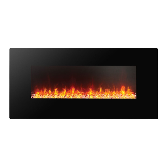
COLUMBUS
we're here to help
1
COLUMBUS LED ELECTRIC FIRE
All instructions must be handed to the user for
safekeeping.
Revision A- 09/16
GB IE
©
2016 Focal Point Fires plc.
Advertisement
Table of Contents

Subscribe to Our Youtube Channel
Related Manuals for Focal Point COLUMBUS EF12-36


Summary of Contents for Focal Point COLUMBUS EF12-36
- Page 1 Please note: Except where otherwise stated, all rights, including copyright in the text, images and layout of this booklet is owned by Focal Point Fires plc. You are not All instructions must be handed to the user for permitted to copy or adapt any of the content without safekeeping.
-
Page 2: Table Of Contents
• From time to time, check the cord for damage. Never use the appliance if the cord or any part of the appliance shows signs of damage. • DO NOT run the mains cable under carpets, rugs etc. © 2016 Focal Point Fires plc. -
Page 3: Installation Requirements
1. M4 x 8mm Screw x 12 2. Large Wall Anchor x 5 3. M5 x 50mm Screw x 5 5.0 COMPONENT CHECKLIST 1. Glass Fascia 2. Firebox 3. Mounting Bracket 4.Table Top Support 5. Front Brace 6. Heat Deflector © 2016 Focal Point Fires plc. -
Page 4: Site Requirements
• The minimum distance from the bottom of the appliance to the floor is 200mm • The minimum distance to the sides of the appliance is 100mm • The minimum distance to the front of the appliance is 500mm © 2016 Focal Point Fires plc. -
Page 5: Installation Wall Mounted
CAUTION: DO NOT CONNECT THE APPLIANCE TO THE WARNING ELECTRICAL SUPPLY AT THIS TIME. Focal Point Fires plc. assumes absolutely no responsibility for injuries and damages The wall where the appliance is to be that may occur due to improper installation or handling. - Page 6 6.Tap 4 large wall anchors (2) into the pre-drilled holes with a hammer until they are flush with the wall. 7. Secure the mounting bracket (3) to the wall by using four M5 x 50 mm screws (3). As shown. © 2016 Focal Point Fires plc.
- Page 7 NOTE: We provided the optional pebbles and crystals for the fuel bed holder.To change the fuel bed follow the following steps below. 10. Arrange the pebbles or crystals on top of the fuel bed holder. © 2016 Focal Point Fires plc.
-
Page 8: Installation Table Top
1. Unpack the unit and confirm that you have all the hardware and required parts. 2. Align and attach the table top support with the table top base by inserting four M4 screws (1) and fully tighten the screws with a phillips screwdriver. © 2016 Focal Point Fires plc. - Page 9 As shown above. 6. Insert three M4 x 8 mm Screws (1) through the mounting holes on the table top support and securely screw into the firebox by a phillips screwdriver. As shown. © 2016 Focal Point Fires plc.
-
Page 10: Operating The Appliance
The buttons on the control panel on the side of the firebox and the remote control function in the same way.The remote control has an effective range of up to 13 feet. 1. Main Power Button 2. Flames Control Button 3.Timer Function Button 4. Side Light Control Button 5.Thermostat On/Off Button 6.Thermostat Control Button (for remote control only) © 2016 Focal Point Fires plc. - Page 11 To change the colour of the lighting press the side light control button (4) again.You can control the side lights colour as described in the table. The colour rotation mode will cycle through the 3 different colour settings continuously. © 2016 Focal Point Fires plc.
- Page 12 5 for several seconds till the temperature indicator flash, then press the button 5 again to select the desired temperature. 1. Main Power Button 2. Flames Control Button 3.Timer Function Button 4. Side Light Control Button 5.Thermostat On/Off Button © 2016 Focal Point Fires plc.
-
Page 13: Safety Cutout System
NOTE: If a moulded plug is fitted and has to be removed take great care in disposing of the plug and severed cable, it must be destroyed to prevent engaging into a socket. Refer to Section 3.0, Appliance Data for fuse specification. Excluding fuses, use only genuine manufacturers spare parts available from your supplier. © 2016 Focal Point Fires plc. -
Page 14: Troubleshooting Guide
3G Service Department to the address below. Alternatively, you can email or fax. Focal Point Fires, 3G Service Department, Reid Street, Christchurch, Dorset, BH23 2BT. Email: 3g@focalpointfires.co.uk, Fax.
Need help?
Do you have a question about the COLUMBUS EF12-36 and is the answer not in the manual?
Questions and answers
Flames not working