Table of Contents
Advertisement
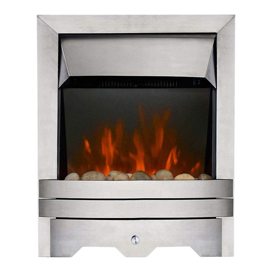
FAN-F F LUE G G AS F F IRE
RANGE
BLENHEIM S S TYLE
ELEGANCE
LULWORTH
INSTALLATION A A ND U U SER
INSTRUCTIONS
All i i nstructions m m ust b b e h h anded t t o u u ser f f or s s afekeeping
Revision A - 05/04
Country(s) of destination - GB/IE
Focal Point Fires plc, Avon Trading Park, Christchurch, Dorset BH23 2BT
Tel: 01202 499330
Fax: 01202 499326
www.focalpoint.co.uk
e-mail: sales@focalpointfires.co.uk
Advertisement
Table of Contents


Need help?
Do you have a question about the BLENHEIM STYLE and is the answer not in the manual?
Questions and answers