Table of Contents
Advertisement
Quick Links
User's Manual
Welcome to the GV-DVR E100 System User's Manual.
The Manual provides an overview of the GV-DVR E100 System and its accessories. It also
includes the instructions to guide you through the installation and use of the GV-DVR E100
System:
Chapter 1, Introduction
•
Identifies the GV-DVR's accessories and options.
Chapter 2, Overview
•
Identifies the GV-DVR's components.
Chapter 3, Getting Started
•
Provides step-by-step instructions on setting up the GV-DVR E100.
Chapter 4, DVR Health Analysis
•
Introduces how to collect data to obtain the service of DVR health analysis
from GeoVision.
Chapter 5, Troubleshooting
•
Suggests courses of action if the GV-DVR doesn't seem to be working properly.
The instructions and figures in this manual are based on GV-System version 8.3.
GV-DVR E100
Advertisement
Table of Contents

Related Manuals for GeoVision GV-DVR E100


Summary of Contents for GeoVision GV-DVR E100
- Page 1 User’s Manual Welcome to the GV-DVR E100 System User’s Manual. The Manual provides an overview of the GV-DVR E100 System and its accessories. It also includes the instructions to guide you through the installation and use of the GV-DVR E100...
-
Page 3: Table Of Contents
Contents Regulatory Notices ....................4 Safety Instructions ....................5 Chapter 1 Introduction ..................6 Unpacking ......................6 Models ........................8 Options ......................... 9 Chapter 2 Overview .....................10 Front View......................10 Rear View ......................11 Chapter 3 Getting Started..................13 Basic Installation ....................13 Turning on the Power ...................14 Configuring an IP Address..................15 Extended Installation ....................17 Recovery DVD .....................20... -
Page 4: Regulatory Notices
Regulatory Notices FCC Notice This equipment has been tested and found to comply with the limits for a Class A digital device, pursuant to part 15 of the FCC Rules. These limits are designed to provide reasonable protection against harmful interference when the equipment is operated in a commercial environment. Class A This equipment generates, uses, and can radiate radio frequency energy and, if not installed and used in accordance with the instruction manual, may cause harmful interference to radio communications. -
Page 5: Safety Instructions
Safety Instructions Observe these safety instructions to help ensure against injury to yourself and damage to the product. Read all safety and installation instructions before you operate the product. Do not operate the product in high humidity areas or expose it to water or moisture. Do not put the product in an unstable, a slanting or vibrated place. -
Page 6: Chapter 1 Introduction
Chapter 1 Introduction 1.1 Unpacking The GV-DVR E100 package includes the following items: Important: Please keep the original carton and all packing materials for future shipping need. 1. GV-DVR E100 System x 1 2. D-Type Audio Cable x 2 / 4 for 32 channel DVR (1 x 1-8 Channels Red Cable, 1 x 9-16 Channels Red Cable) 3. - Page 7 8. Recovery DVD x 1 9. Nero Express CD x 1 10. Surveillance System Software CD x 1 11. GV-DVR E100 System User’s Manual x 1 12. Surveillance System New Feature Guide x 1 13. Surveillance System Installation Guide x 1...
-
Page 8: Models
1.2 Models The GV-DVR E100 is available in the following configurations: - Sixteen-channel digital video recorder GV-2016 - Records up to 400 (PAL) fps at the D1 resolution - Has the option of 1500GB, 2000GB, 2500GB internal storage GV-2008 - Eight-channel digital video recorder... -
Page 9: Options
Introduction 1.3 Options Optional devices can expand your GV-DVR E100’s capabilities and versatility. Contact your dealer for more information. With 12-point digital inputs, this card can expand the GV-DVR up to GV-IO 12-In Card 16 sensor inputs. GV-IO 12-Out Card With 12-point relay outputs, this card can expand the GV-DVR up to 16 alarm outputs. -
Page 10: Chapter 2 Overview
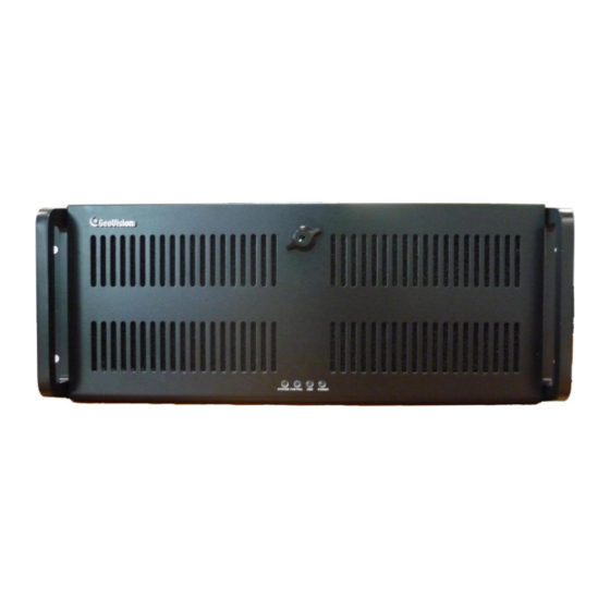
Chapter 2 Overview 2.1 Front View Figure 1 System LED Reset switch Fan fail LED Power switch HDD LED Power LED DVD ± RW Drive USB Port x 2 Key lock 5.25” Hard Disk Compartment... -
Page 11: Rear View
Overview 2.2 Rear View Figure 2 AC Power Switch Audio Line In Port AC Power Input (Full Range) Rear speaker out (for HD audio) PS/2 Keyboard Input Audio Line Out Port USB Port x 2 Side speaker out (for HD audio) HDMI interface Audio Microphone In Port VGA Monitor Port (D-sub) -
Page 13: Chapter 3 Getting Started
Chapter 3 Getting Started 3.1 Basic Installation Basic installation describes all the equipments required to program and operate the GV-DVR E100. Figure 3 1. Using the supplied power cord, connect one end to the AC input and the other end to the power outlet. -
Page 14: Turning On The Power
3.2 Turning on the Power Once the above hardware is properly connected, it is the time to turn on the GV-DVR. To turn on the power, follow these steps: 1. Turn on the monitor. Figure 4 2. Turn on the AC power switch on the rear panel. Figure 5 3. -
Page 15: Configuring An Ip Address
GV-DVR over a network connection. The GV-DVR is enabled for DHCP network. An IP address will be automatically allocated when the GV-DVR E100 is powered up. Despite the DHCP setting, it is recommended that a static IP address be configured on the unit. - Page 16 5. Configure a static IP address on the Windows XP platform. Check your network administrator if you have questions about the configuration. Figure 8 The GV-Desktop Back to GV-Desktop Click the Windows Start button, point to Programs, select GVCombo, and click Key Lock Utility. Figure 9 Windows XP desktop...
-
Page 17: Extended Installation
For details on the GV-Keyboard, find the Installation Manual included in its own package. Figure 10 It is also possible to plug the Keyboard into other USB ports of the GV-DVR E100. For this, you must modify the default COM port on the Multicam Controller pop-up once the Keyboard is connected. See... -
Page 18: Ir Remote Control
IR Remote Control The IR Remote Control is another plug-and-play device. Simply plug the Receiver into any USB ports of the GV-DVR E100. For details on the IR Remote Control, find the User’s Manual included in its own package. Figure 12... -
Page 19: Ptz Domes
Getting Started I/O Devices The GV-DVR E100, with built-in GV-NET/IO Card, provides 4 alarm outputs and 4 sensor inputs. Figure 13 PTZ Domes When connecting PTZ domes, you need to plug the supplied RJ-11 to DB9 cable into the DB9 port of the GV-DVR E100. -
Page 20: Recovery Dvd
3.5 Recovery DVD If preinstalled files are damaged, use the supplied Recovery DVD to restore them. To restore the operation system and all preinstalled software, follow these steps: Note: After recovery, you need to re-install all settings and passwords. But the recovery will not delete your recording files saved in the GV-DVR since it only reformats the partition C and all of your files are still stored at other partitions. - Page 21 Getting Started Configuring the GV-DVR E100 for PAL after Recovery The default video standard of the Recovery DVD is set to NTSC. If the video standard in your country is PAL, remember to configure the GV-DVR for PAL after using the Recovery DVD.
-
Page 22: Updating Gv-Dvr System
3.6 Updating GV-DVR E100 System GeoVision will periodically release the updated Recovery DVD including the latest GV-System Software (Multicam Surveillance System) and Windows updates. If you like to update your GV-DVR E100 System, contact your dealer to get one. Before contacting your dealer, you may check software update news at our website:... -
Page 23: Dvr Health Analysis
DVR Health Analysis Chapter 4 DVR E100 Health Analysis GeoVision offers health analysis to the GV-DVR. The service is intended to give diagnosis for early and immediate detection of problems. It is recommended to have the health analysis during the first week after you install the GV-DVR, and then have the checkup every three months. - Page 24 2. Select Backup System Settings. This dialog box appears. Figure 20 3. Press the Next Step button to back up all your system settings. The Save As dialog box appears. 4. Select the destination drive to store the backup file. When the backup is complete, this message will appear: Successfully Backup MultiCam System Settings.
-
Page 25: System Log
DVR Health Analysis 4.2 System Log Please provide the sys*.mdb files of system log. The files by default are saved at D:\Log\database. If you have modified the default location, you can check the path by the following steps: 1. Click the Configure button on the main system, point to General Setting, and then select System Log Setting. -
Page 26: Information Of Your Computer System
4.3 Information of Your Computer System To get the information of your computer system, please follow the steps below to install the free software PC WIZARD. By using the software, the computer information can be easily collected and saved for analysis: Processor: includes Type, Frequency, Data Cache L1, Trace Cache L1, Cache L2, Voltage, Processor Temperature, FPU Coprocessor. - Page 27 DVR Health Analysis 4. In the Save As dialog box, select Format HTML and click OK. Figure 24 5. Select the Save location, type the file name, and then click Save to save the Processor information as HTML file. 6. Repeat Steps 3-5 to save the Drives information as HTML file.
-
Page 28: Health Analysis Form
4.4 Health Analysis Form Please send the related data for analysis along with this Health Analysis Form to dvrsystem@geovision.eu Health Analysis of GV-DVR E100 Contact Person: Title: Company Name: Telephone: (O) Fax: E-Mail: Model: Bar Code: 4.5 Check List Read this check list before submitting the health analysis request: System Settings- EXE file System Log- sys*.mdb... -
Page 29: Chapter 5 Troubleshooting
When the portable 2.5” HDD connected to a GV-DVR E100 cannot be detected, try this step: Use a dual head USB cable and insert both heads to the USB ports on the GV-DVR E100 front panel as illustrated below. - Page 30 The Main System cannot be minimized, and the GV-Desktop toolbar fails to appear. When the GV-DVR is set up in a LAN where its router or server cannot assign the IP addresses through DHCP, the Main System may not be minimized, and the GV-Desktop toolbar may fail to appear. Try these steps: 1.
- Page 31 Troubleshooting D. Select Network Connections, right-click Local Area Connection, and then select Properties. Figure 28 In the Local Area Connection Properties dialog box, select Internet Protocol (TCP/IP) and then click Properties. Figure 29...
- Page 32 Select Use the following IP address, and type the IP info in the fields. Figure 30 2. Replace the router or server that can assign the IP addresses through DHCP in a LAN. GV-DVR won’t turn on. If your GV-DVR won’t turn on or you don't hear a startup sound or any fan or drive noise, try these steps: 1.
- Page 33 Troubleshooting GV-DVR stops responding (aka “crashed” or froze”). If your GV-DVR is not responding to your clicking, typing, or mouse movements, try these steps to get your GV-DVR back on track. Please note that you will lose any unsaved changes in all open applications.
- Page 34 C. Click the Tools tab in the upper portion of the window. D. Under Error-checking, click the Check Now button. Figure 34 E. Select Automatically fix file system errors and Scan for and attempt recovery of bad sectors. Figure 35 F.
- Page 35 2. Make sure the camera and its cable are not damaged or frayed. Try to replace a camera or camera cable to see if this fixes the problem. How can I find more help? 1. Visit our website at http://www.geovision.com.tw/english/4_1.asp 2. Write us at dvrsystem@geovision.eu...
-
Page 36: Specifications
Specifications System Model GV-2016 GV-2008 GV-1480 GV-1240/800 GV-1120/650 Intel Pentium Core 2 Quad Processor 2 GB 1 GB 1 GB Dual Channel Dual Channel Dual Channel 1500 GB 1500 GB 500 GB 500 GB 500 GB 2000 GB 2000 GB 1500 GB 1000 GB 1000 GB... - Page 37 Specifications Audio Model GV-2016 GV-2008 GV-1480 GV-1240 GV-1120 GV-800 GV-650 16/32 8 / 16 / 16 / 32 Audio Input 4/8 ch 1/2 ch 32 ch Input Level 0.5 ~ 1 Vp-p composite Compression ADPCM / G.723 Recording Model GV-2016 GV-2008 GV-1480 GV-1240...
-
Page 38: Remote Client Software
Remote Client Software WebCam / Twin Server / CenterV2 / VSM / Control Center / Remote Playback Server / Remote View / IP Multicast / Monitoring GView V2 for PDA / MSView V2 for Windows Mobile 5.0 / MSView V3 Environment for Windows Mobile 6.0 / SSView V2 for Symbian Smartphone /... - Page 39 Specifications Environment Operating Temp. 0 ~ 50 ° C (32 ~ 122 ° F) Humidity 0 ~ 80% RH (non-condensing) Physical Model GV-2016 GV-2008 GV-1480 GV-1240/800 GV-1120/650 IPC Case 4U Rackmount Black Color Dimensions 483 (W) x 178 (H) x 528 (D) mm (19 x 7 x 21 inch) Language English / Czech / French / German / Hebrew / Hungarian / Italian / Polish / Portuguese (Brazil) / Russian / Spanish...
-
Page 40: Warranty Policy
Other packaged accessories and software (including but not limited to System Software) are excluded. If a defect where due to causes attributable to GeoVision arises and a valid claim is received by GeoVision within the Limited Warranty Period, at its option, GeoVision will (1) repair the product at no... - Page 41 EXPRESSED OR IMPLIED WILL APPLY AFTER THIS PERIOD. GEOVISION SHALL NOT BE LIABLE FOR SPECIAL, DIRECT, INDIRECT, CONSEQUENTIAL DAMAGES. GEOVISION SHALL NOT BE LIABLE FOR LOST PROFITS, LOST OF DATA, PROGRAMS OR OTHER INFORMATION, DAMAGE TO OTHER PROPERTY CAUSED BY ANY...
- Page 42 2. Securely pack the product in its original carton using the original packing material, or in equivalent packaging. 3. The product shall be returned to GeoVision Subsidiary in Czech Republic at your expense for shipping and insurance costs. BEFORE YOU DELIVER YOUR GV-DVR E100 FOR WARRANTY SERVICE, IT IS YOUR RESPONSIBILITY TO BACK UP YOUR DATA.
-
Page 43: Warranty Form
Warranty policy Warranty Form Thank you for purchasing the GV-DVR E100. To help us validate your purchase and better serve you in the future, please fill in this form and return to Europe Vision Systems by fax, email or mail. - Page 44 Shipment Date: GeoVision, Inc. GeoVision, Inc. Europe Vision Systems 9F, No. 246, Sec. 1, Neihu Rd., Pod Vinici 2028/20 Neihu District, Taipei, Taiwan Tel: +886-2-8797-8377 Prague 14301 Czech Republic Fax: +886-2-8797-8335 Tel: +420 225 371 121 Email: sales@geovision.com.tw Fax: +420 225 371 131 dvrsystem@geovision.com.tw...
Need help?
Do you have a question about the GV-DVR E100 and is the answer not in the manual?
Questions and answers