Table of Contents
Advertisement
Quick Links
Advertisement
Table of Contents

Related Manuals for SHOWTEC Explorer 1200


Summary of Contents for SHOWTEC Explorer 1200
- Page 1 Explorer 1200 ORDERCODE 40195...
- Page 2 Congratulations! You have bought a great, innovative product from Showtec. The Showtec Explorer 1200 brings excitement to any venue. Whether you want simple plug-&-play action or a sophisticated DMX show, this product provides the effect you need. You can rely on Showtec, for more excellent lighting products.
-
Page 3: Table Of Contents
Showtec Showtec Explorer 1200 Product Guide ™ Warning..…...................………………………………………….. Safety-instructions………………………………………………………………………………………….…. Operating Determinations……………………………………………………………………………………. Rigging…………………………………………………………………………………………………………. Mounting a clamp to the underside of the Explorer moving head……………………………………….. Description..…................……….………………………………… Features and Overview ………………………………...….……………….………….………………….…. Backside…………………………………………………...…...….……………….…………………...….…. Installation................…...…………………………………….….. Installing the Lamp ............………………………………………..………… Lamp Adjustment.…............………………………………………..………… Set Up and Operation..............……..……………………………….…... -
Page 4: Warning
WARNING CAUTION! Keep this device away from rain and moisture! Unplug mains lead before opening the housing! FOR YOUR OWN SAFETY, PLEASE READ THIS USER MANUAL CAREFULLY BEFORE YOUR INITIAL START-UP! SAFETY INSTRUCTIONS Every person involved with the installation, operation and maintenance of this device has to: be qualified follow the instructions of this manual CAUTION! Be careful with your operations. -
Page 5: Operating Determinations
The arising condensation water might damage your device. Leave the device switched off until it has reached room temperature. If your Showtec device fails to work properly, discontinue use immediately. Pack the unit securely • (preferably in the original packing material), and return it to your Showtec dealer for service. -
Page 6: Rigging
Rigging Please follow the European and national guidelines concerning rigging, trussing and all other safety issues. Do not attempt the installation yourself ! Always let the installation be carried out by an authorized dealer ! Procedure: If the projector is lowered from the ceiling or high joists, professional trussing systems have to be •... -
Page 7: Mounting A Clamp To The Underside Of The Explorer Moving Head
Mounting a clamp to the underside of the Explorer moving head Improper installation can cause serious damage to people and property ! Connection with the mains Connect the device to the mains with the power-plug. Always pay attention, that the right color cable is connected to the right place. Cable International BROWN... -
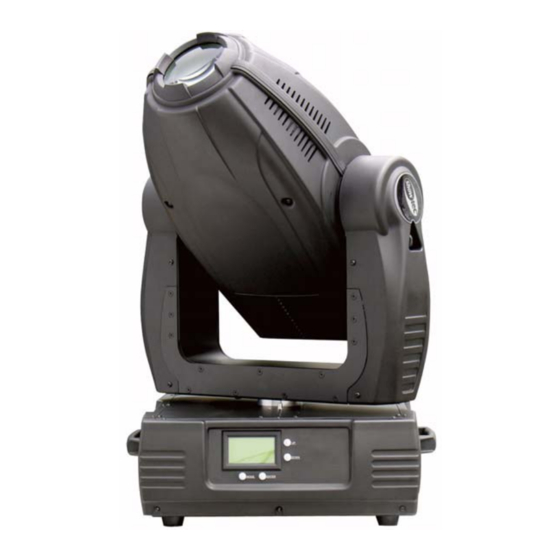
Page 8: Description
Description of the device Features The Showtec Explorer 1200 is a moving head with high output and great effects. • 1 Color-wheel with 6 colored gobos, CTF 6000ºK and open • 2 Gobo-wheels with 5 metal and 7 rotating glass gobos plus open •... -
Page 9: Backside
Backside Fig. 2 4) Fuse 10A 230V ON / OFF DMX signal connector (OUT) 5-pin DMX signal connector (OUT) 3-pin DMX signal connector (IN) 5-pin DMX signal connector (IN) 3-pin... -
Page 11: Installation
Installation Installing the Lamp The Showtec Explorer 1200 uses the MSR 1200SA (ordercode 80950) bulb as manufactured by all popular manufacturers. Use only the appropriate lamp for your unit. Note that, product versions that use other lamps, may be offered in the future. Check your product specification label for information. -
Page 12: Lamp Adjustment
Lamp Adjustment You can adjust the lamp’s position by turning the screws X, Y, Z. The lamp position is set in the factory. As the lamps, which can be used, differ from manufacturer to manufacturer, it can be necessary to readjust the position. The lamp must be readjusted e.g., if the light does not seem to be evenly distributed within the ray of light. -
Page 13: Set Up And Operation
Set Up and Operation Follow the directions below, as they pertain to your preferred operation mode. Before plugging the unit in, always make sure that the power supply matches the product specification voltage. Do not attempt to operate a 120V specification product on 230V power, or vice versa. One Explorer 1. - Page 14 Multiple Explorers Set Up DMX-Set up Fig. 4 Note : Link all cables before connecting electric power...
-
Page 16: Menu Settings
DMX Protocol Channel 1 - Horizontal movement (Pan) Push the slider up, in order to move head horizontally (PAN). Gradual head adjustment from one end of the slider to the other (0-255, 128-center). The head can be turned by 540°and stopped at any position you wish. Channel 2 - Pan fine 16 bit Channel 3 - Vertical movement (Tilt) Push the slider, up in order to move head vertically (TILT). - Page 17 Channel 10 – Yellow 0-255 Gradual adjustment Yellow from 0% -100% Channel 11 – Color Correction 6000ºK - 3200ºK 6000ºK 3200ºK Channel 12 – CMY + CTF Change Speed 0-255 Gradual adjustment from slow to fast Channel 13 – Rotating Gobo wheel A 0-15 Open / white 16-31...
- Page 18 Channel 16 – Rotating gobo index, rotating gobo rotation Gobo wheel B 0-60 0 – 540º indexing 61-158 Forwards gobo rotation from slow to fast 159-255 Backwards gobo rotation from slow to fast Channel 17 – Prism wheel 0-51 Open 52-104 Diamond 105-157...
-
Page 19: Control Panel
Channel 24 – Dimmer intensity 0-255 Gradual adjustment dimmer intensity from 0-100% The Explorer 1200 can be operated with a controller in control mode or without the controller in stand- alone mode. Control Panel When the indicator light is on, means the Explorer is working Fig. - Page 20 - The controller is switched off or defective, the cable or connector is detective, or the signal wires are swapped in the input connector. Note: It’s necessary to insert a XLR termination plug (with 120 Ohm) in the last fixture in order to ensure proper transmission on the DMX data link.
-
Page 21: Channel Settings
Channels settings... -
Page 22: Maintenance
3. Mechanically moving parts like axles, eyes and others may not show any traces of wearing. 4. The electric power supply cables must not show any damages or material fatigue. The Showtec Explorer 1200 requires almost no maintenance. However, you should keep the unit clean. Otherwise, the fixture’s light-output will be significantly reduced. -
Page 23: Replacing A Gobo From The Rotating Gobowheel
Replacing a Gobo from the Rotating Gobowheel Gobo-wheel with rotating gobo’s 1. Disconnect mains power supply and set the switch to OFF. 2. Make sure that the gobo you want to insert has the same size. Fig. 6 3. Gently bend out the gobo holder to release it from the fixative holes and eject it from the pressing snap. Press the ends of the spring gobo-lock together with a pair of pliers and remove it. -
Page 24: Replacing A Gobo From The Effect Wheel
Replacing a Gobo from the Effect wheel 1. Disconnect mains power supply and set the switch to OFF. 2. Make sure that the gobo you want to insert has the same size. Fig. 8 3. Gently bend out the effect glass holder to release it from the fixative holes and eject it from the pressing snap. - Page 25 Problem Probable cause(s) Remedy No power to the fixture ·Check that power is switched on and One or more cables are plugged in. fixtures are Primary fuse blown. ·Replace fuse. completely dead. Fixtures reset The controller is not connected. ·Connect controller. correctly, but all 3-pin XLR Out of the controller ·Install a phase reversing cable...
-
Page 26: Product Specifications
Product Specification Model: Showtec Explorer 1200 Voltage: 240V-50Hz (CE) Power: 1600W Fuse: 10A / 250V Dimensions: 525x489x602mm (LxWxH) Weight: 60 kg Operation and Programming Signal pin OUT: pin 1 earth, pin 2 (-), pin 3 (+) Set Up and Addressing: LED control panel...
Need help?
Do you have a question about the Explorer 1200 and is the answer not in the manual?
Questions and answers