Table of Contents
Advertisement
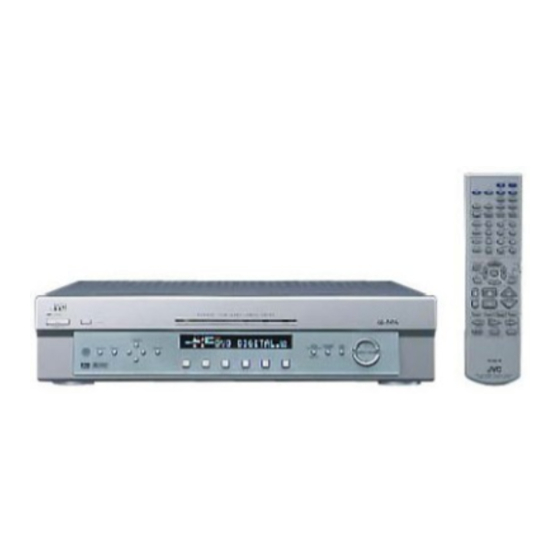
HOME CINEMA CONTROL CENTER
RX-E100RSL
AUDIO
DVD
STB
VCR
SLEEP
DVD
STB
VCR
ANALOG/DIGITAL
TAPE
FM
INPUT
SOUND
BASS+
CENTER
1
2
TEST
BASS–
REAR-L
4
5
BASS BOOST
TREBLE+
REAR-R
7
8
EFFECT
TREBLE–
SUBWOOFER
0
10
RETURN
FM MODE
EON SELECT
DISPLAY MODE
DVD MENU
EON
PTY(
ENTER
DSP
MODE
PTY SEARCH
TV VOL
CHANNEL
VOLUME
TV/VIDEO
DIMMER
VCR
CONTROL
/REW
PLAY
DOWN
TUNING
REC
STOP
RM-SRXE100R
REMOTE CONTROL
HOME CINEMA CONTROL CENTER
TV
TV DIRECT
TV
AM
3
6
9
+10
100+
RDS
DVD
MENU
PTY9
SURROUND
ON/OFF
MUTING
STANDBY
TV DIRECT
FF/
STANDBY/ON
UP
PAUSE
CONTROL
SETTING
ADJUST
D I G I T A L
D I G I T A L
S U R R O U N D
INSTRUCTIONS
RX-E100R
HOME CINEMA CONTROL CENTER
DVD
STB
VCR
TV
TAPE
FM/AM
ANALOG
L
C
R
PRO LOGIC
SLEEP
TUNED
ST
AUTO
MUTING
LPCM
DSP
MH
SUBWFR LFE
Z
DOLBY D
DGTL AUTO
KH
Z
LS
S
RS
INPUT
DTS
INPUT ATT
VOL
MEMORY
ANALOG/DIGITAL
INPUT ATT
DVD
DVD
STB
VCR
TV
TAPE
FM/AM
For Customer Use:
SURROUND
DSP
ON/OFF
MODE
MASTER VOLUME
Enter below the Model No. and Serial
No. which are located either on the rear,
bottom or side of the cabinet. Retain this
information for future reference.
Model No.
Serial No.
LVT0650-003A
[B]
Advertisement
Table of Contents

Related Manuals for JVC RX-E100RSL


Summary of Contents for JVC RX-E100RSL
- Page 1 HOME CINEMA CONTROL CENTER RX-E100RSL AUDIO SLEEP TV DIRECT ANALOG/DIGITAL TAPE INPUT SOUND BASS+ CENTER TEST BASS– REAR-L BASS BOOST TREBLE+ REAR-R EFFECT TREBLE– SUBWOOFER 100+ RETURN FM MODE EON SELECT DISPLAY MODE DVD MENU MENU PTY( PTY9 ENTER SURROUND...
- Page 2 Warnings, Cautions and Others IMPORTANT for the U.K. DO NOT cut off the mains plug from this equipment. If the plug fitted is not suitable for the power points in your home or the cable is too short to reach a power point, then obtain an appropriate safety approved extension lead or consult your dealer.
-
Page 3: Safety Instructions
No obstructions in 15 cm from the back Bottom: No obstructions, place on the level surface. In addition, maintain the best possible air circulation as illustrated. Wall or obstructions SAFETY INSTRUCTIONS Spacing 15 cm or more RX-E100RSL Front Stand height 15 cm or more Floor... -
Page 4: Table Of Contents
Table of Contents Parts Identification ... 2 Getting Started ... 3 Before Installation ... 3 Checking the Supplied Accessories ... 3 Putting Batteries in the Remote Control ... 3 Connecting the FM and AM (MW/LW) Antennas ... 4 Connecting the Speakers ... 5 Connecting Audio/Video Components ... -
Page 5: Parts Identification
Parts Identification Front Panel STANDBY TV DIRECT STANDBY/ON CONTROL ADJUST SETTING D I G I T A L D I G I T A L S U R R O U N D Remote Control AUDIO SLEEP TV DIRECT ANALOG/DIGITAL TAPE INPUT SOUND... -
Page 6: Getting Started
Getting Started Before Installation General Precautions • DO NOT insert any metal object into the unit. • DO NOT disassemble the unit or remove screws, covers, or cabinet. • DO NOT expose the unit to rain or moisture. Locations • Install the unit in a location that is level and protected from moisture. -
Page 7: Connecting The Fm And Am (Mw/Lw) Antennas
Getting Started Connecting the FM and AM (MW/LW) Antennas AM (MW/LW) Loop Antenna (supplied) Snap the tabs on the loop into the slots of the base to assemble the AM (MW/LW) loop antenna. If AM (MW/LW) reception is poor, connect single vinyl-covered wire (not supplied). If FM reception is poor, connect outdoor FM antenna (not supplied). -
Page 8: Connecting The Speakers
AM (MW/LW) antenna connection Connect the AM (MW/LW) loop antenna supplied to the AM LOOP terminals. Turn the loop until you have the best reception. • If reception is poor, connect an outdoor single vinyl-covered wire to the AM EXT terminal. Keep the AM (MW/LW) loop antenna connected. - Page 9 Getting Started Speaker Layout Diagram Center speaker Left front speaker Left rear speaker RX-E100R L IN IT A IT A D IG D IG R IG ( D V E A K L E F T E R R IG IT A C E N D IG...
-
Page 10: Connecting Audio/Video Components
Connecting Audio/Video Components Turn the power off to all components before connections. Connecting cords are not supplied with this unit. Use the cords supplied for the other components or purchase them at an audio or electric appliance store. Coaxial digital cord Optical digital cord Digital connections DIGITAL IN... - Page 11 Getting Started Turn the power off to all components before connections. RX-E100R L O O D IO (R E SCART Terminal Specifications AUDIO Composite VIDEO S-VIDEO AUDIO Composite VIDEO S-VIDEO T-V LINK Illustrations of the input/output terminals below are typical examples.
-
Page 12: Connecting The Power Cord
DVD Player STANDBY STANDBY ON DOLBY D I G I T A L For TV and video format When the TV is equipped with the plural SCART terminals, see the manual supplied with the TV to check the available video signals for each terminal, then connect SCART cable correctly. -
Page 13: Basic Operations
Basic Operations This manual mainly explains operations using the buttons and controls on the front panel. You can also use the buttons on the remote control if they have the similar names (or marks) as those on the front panel. If operations using the remote control are different from those using the front panel, they are then explained. -
Page 14: Activating Tv Direct
Activating TV Direct TV Direct is enable you to use this unit as an AV selector while the unit is not turned on. When TV Direct is activated, the pictures and sounds go from the video components such as DVD player to the TV through this unit. In this case, you can use the video components and the TV as if you connect them directly. -
Page 15: Turning Off The Sounds Temporarily
Basic Operations AUDIO SLEEP TV DIRECT SLEEP ANALOG/DIGITAL TAPE INPUT SOUND BASS+ CENTER BASS– REAR-L TEST BASS BOOST TREBLE+ REAR-R EFFECT TREBLE– SUBWOOFER RETURN FM MODE EON SELECT DISPLAY MODE DVD MENU PTY( ENTER MODE PTY SEARCH TV VOL CHANNEL VOLUME DIMMER TV/VIDEO... -
Page 16: Basic Settings
Basic Settings CONTROL 5/∞/3/2 STANDBY TV DIRECT STANDBY/ON SETTING ADJUST D I G I T A L D I G I T A L S U R R O U N D SETTING Setting the Digital Input Terminals When you use the digital input terminals, register what components are connected to which terminals (DIGITAL IN 1/2) so that the correct source name will appear when you select the digital source. - Page 17 Basic Settings CONTROL 5/∞/3/2 STANDBY TV DIRECT STANDBY/ON CONTROL SETTING ADJUST D I G I T A L D I G I T A L S U R R O U N D SETTING DGTL AUTO : Select this for the digital input mode. The unit automatically detects the incoming signal format.
-
Page 18: Setting The Subwoofer Information
Setting the Subwoofer Information When you have connected a subwoofer, follow the procedure below. If you do not use a subwoofer, you can skip this setting. Before you start, remember... There is a time limit in doing the following steps. If the setting is canceled before you finish, start from step 1 again. - Page 19 Basic Settings CONTROL 5/∞/3/2 STANDBY TV DIRECT STANDBY/ON CONTROL SETTING ADJUST D I G I T A L D I G I T A L S U R R O U N D SETTING Delay Time — CTR DL, REAR DL Adjust the delay time of the sounds from the center speaker and from the rear speakers, comparing to that of the sound from the front speakers.
- Page 20 Crossover Frequency — CROSS Small speakers cannot reproduce the bass sounds efficiently. If you use a small speaker in any position, this unit automatically reallocates the bass sound elements assigned to the small speaker to the large speakers. To use this function properly, set this crossover frequency level according to the size of the small speaker connected.
-
Page 21: Setting Auto Surround
Basic Settings CONTROL 5/∞/3/2 STANDBY TV DIRECT STANDBY/ON CONTROL SETTING ADJUST D I G I T A L D I G I T A L S U R R O U N D SETTING Low Frequency Effect Attenuator — LFE If the bass sound is distorted while playing back software using Dolby Digital or DTS Digital Surround, follow the procedure below. -
Page 22: Setting Tv Direct Mode
: • If multichannel signals come in, an appropriate Surround mode will be turned on. • If Dolby Digital 2 channel or DTS 2 channel signals come in, “STEREO” will be selected. • If Linear PCM signals come in, nothing will change. -
Page 23: Sound Adjustments
Sound Adjustments You can also use the remote control for some sound adjustments. • When using the remote control, see also “Mastering Remote Operations” on page 40. CONTROL 5/∞/3/2 STANDBY TV DIRECT STANDBY/ON CONTROL SETTING ADJUST D I G I T A L D I G I T A L S U R R O U N D ADJUST... -
Page 24: Reinforcing The Bass
Reinforcing the Bass You can boost the bass level — Bass Boost. • You have to make this adjustment for each source. Before you start, remember... There is a time limit in doing the following steps. If the setting is canceled before you finish, start from step 1 again. -
Page 25: Adjusting The Subwoofer Output Level
Sound Adjustments CONTROL 5/∞/3/2 STANDBY TV DIRECT STANDBY/ON SETTING ADJUST D I G I T A L D I G I T A L S U R R O U N D ADJUST Adjusting the Subwoofer Output Level You can adjust the subwoofer output level if you have connected a subwoofer and set the subwoofer information correctly –... -
Page 26: Tuner Operations
Tuner Operations CONTROL 5/∞/3/2 STANDBY TV DIRECT STANDBY/ON CONTROL SETTING ADJUST D I G I T A L D I G I T A L S U R R O U N D Tuning in Stations Manually Press FM/AM to select the band. The last received station of the selected band is tuned in, and the CONTROL buttons now work for tuner operations. -
Page 27: Using Preset Tuning
Tuner Operations CONTROL 5/∞/3/2 STANDBY TV DIRECT STANDBY/ON CONTROL SETTING ADJUST D I G I T A L D I G I T A L S U R R O U N D Using Preset Tuning Once a station is assigned to a channel number, the station can be quickly tuned. -
Page 28: Selecting The Fm Reception Mode
To tune in a preset station Press FM/AM to select the band. The last received station of the selected band is tuned in, and the CONTROL buttons now work for tuner operations. TUNED FM/AM Ex.: When selecting the FM band Press CONTROL ∞... -
Page 29: Using The Rds (Radio Data System) To Receive Fm Stations
Tuner Operations You need to set RDS/DVD MENU selector to “RDS,” when you want to operate RDS. AUDIO SLEEP TV DIRECT ANALOG/DIGITAL TAPE INPUT SOUND BASS+ CENTER BASS– REAR-L TEST BASS BOOST TREBLE+ REAR-R EFFECT TREBLE– SUBWOOFER SELECT RETURN FM MODE 100+ EON SELECT DISPLAY... -
Page 30: Searching For A Program By Pty Codes
Searching for a Program by PTY Codes One of the advantages of the RDS service is that you can locate a particular kind of program from the preset channels (see page 24) by specifying the PTY codes. To search for a program using the PTY codes Before you start, remember... - Page 31 Tuner Operations You need to set RDS/DVD MENU mode selector to “RDS,” when you want to operate RDS. AUDIO SLEEP TV DIRECT ANALOG/DIGITAL TAPE INPUT SOUND BASS+ CENTER BASS– REAR-L TEST BASS BOOST TREBLE+ REAR-R EFFECT TREBLE– SUBWOOFER SELECT RETURN FM MODE 100+ EON SELECT...
-
Page 32: Switching To A Broadcast Program Of
Switching to Broadcast Program of Your Choice Temporarily Another convenient RDS service is called “EON (Enhanced Other Network).” The EON indicator works and lights up while receiving an FM station with the EON code. This allows the unit to switch temporarily to a broadcast program of your choice (TA, NEWS, and/or INFO) from a different station except in the following cases: •... -
Page 33: Creating Realistic Sound Fields
This fact allows DTS Digital Surround format to add breadth and depth to the reproduced sounds. As a result, DTS Digital Surround features natural, solid and clear sound. JVC Theatre Surround Used to reproduce sound tracks of the software encoded with Dolby Surround ( DOLBY SURROUND •... - Page 34 DAP (Digital Acoustic Processor) Modes DAP modes have been designed to create important acoustic surround elements. The sound heard in a hall, live club, dance club or pavilion consists of direct sound and indirect sound — early reflections and reflections from behind. Direct sounds reach the listener directly without any reflection.
-
Page 35: About Relations Between Speaker Layout And Dsp Modes
Creating Realistic Sound Fields About Relations between Speaker Layout and DSP Modes Available DSP modes will vary depending on how many speakers are used with this unit. Make sure that you have set the speaker information correctly (see page 15). •... -
Page 36: Using Surround Modes (Remote Control)
It will be convenient for you to use the remote control for DSP operations, since you can adjust them from your listening point, and use the test signal. • When using the buttons on the front panel, see pages 37 to 39. - Page 37 Creating Realistic Sound Fields AUDIO SLEEP TV DIRECT ANALOG/DIGITAL TAPE INPUT SOUND BASS+ CENTER SOUND BASS– REAR-L TEST TEST BASS BOOST TREBLE+ REAR-R EFFECT TREBLE– SUBWOOFER EFFECT RETURN FM MODE 100+ EON SELECT DISPLAY MODE MENU DVD MENU PTY( PTY9 ENTER SURROUND DSP MODE...
-
Page 38: Using Theatre Surround (Remote Control)
Using Theatre Surround (Remote Control) Theatre Surround cannot be used with another DSP mode. Once Theatre Surround is activated, the other DSP mode in use will be canceled. • You have to make this adjustment for each source. • You cannot use Theater Surround if no rear speakers are connected. -
Page 39: Using Dap Modes (Remote Control)
Creating Realistic Sound Fields AUDIO SLEEP TV DIRECT ANALOG/DIGITAL TAPE INPUT SOUND BASS+ CENTER SOUND BASS– REAR-L TEST BASS BOOST TREBLE+ REAR-R EFFECT TREBLE– SUBWOOFER EFFECT RETURN FM MODE 100+ EON SELECT DISPLAY MODE MENU DVD MENU PTY( PTY9 ENTER SURROUND DSP MODE MODE... -
Page 40: Using Surround Modes (Front Panel)
CONTROL 5/∞/3/2 STANDBY TV DIRECT STANDBY/ON SETTING ADJUST D I G I T A L D I G I T A L S U R R O U N D ADJUST Before you start, remember... • Make sure that you have set the speaker information correctly (see page 15). -
Page 41: Using Theatre Surround (Front Panel)
Creating Realistic Sound Fields CONTROL 5/∞/3/2 STANDBY TV DIRECT STANDBY/ON SETTING ADJUST D I G I T A L D I G I T A L S U R R O U N D ADJUST CENTER : To adjust the center speaker output level (from –10 to +10). -
Page 42: Using Dap Modes (Front Panel)
CENTER : To adjust the center speaker output level (from –10 to +10). REAR L : To adjust the left rear speaker output level (from –10 to +10). REAR R : To adjust the right rear speaker output level (from –10 to +10). EFFECT : To adjust the DSP effect level. -
Page 43: Mastering Remote Operations
Mastering Remote Operations You can use the remote control to operate not only this unit but also other JVC products. • Refer also to the manuals supplied for the other products. – This remote control can operate a VCR whose remote control code is set to A code. - Page 44 PLAY DOWN TUNING STOP PAUSE Operating other JVC’s products Turning on the Power — POWER buttons : Turn on or off a DVD player. : Turn on or off an STB. : Turn on or off a VCR. : Turn on or off a TV.
- Page 45 These buttons works only for TVs. TV/VIDEO TV VOL PAUSE TV VOL +/– TV/VIDEO Operating DVD menu for JVC DVD player DISPLAY MODE DVD MENU PTY( After setting RDS/DVD MENU selector to “DVD MENU,” you can use the buttons illustrated above for DVD menu operations.
-
Page 46: Operating Other Manufacturers' Equipment
Operating other Manufacturers’ Equipment By changing the transmittable signals, you can use the remote control supplied for this unit to operate other manufacturers’ equipment. • Refer also to the manuals supplied for the other products. • To operate these components with the remote control, first you need to set the manufacturer’s code each for DVD player, STB, VCR, and TV. - Page 47 Mastering Remote Operations To change the transmittable signals for operating an 1. Press and hold VCR 2. Press VCR. 3. Enter manufacturer’s code using buttons 1–9, and 0. 4. Release VCR Now, you can perform the following operations on the VCR. : Turn on or off the VCR.
-
Page 48: Troubleshooting
Troubleshooting Use this chart to help you solve daily operational problems. If there is any problem you cannot solve, contact your JVC service center. PROBLEM The power does not comes on. No sound from speakers. Sound from one speaker only. -
Page 49: Specifications
Specifications Amplifier Output Power Audio Audio Input Sensitivity/Impedance (1 kHz): Audio Input (DIGITAL IN)* : Audio Output Level: Signal-to-Noise Ratio (’66 IHF/DIN): Frequency Response (8 ): Tone Control: Bass Boost: Video Video Input Sensitivity/Impedance (1 kHz): Composite video: S-VIDEO: RGB: Video Output Level/Impedance (1 kHz): Composite video: S-VIDEO:... - Page 50 VICTOR COMPANY OF JAPAN, LIMITED 0301NHMMDWJEIN...
Need help?
Do you have a question about the RX-E100RSL and is the answer not in the manual?
Questions and answers